Advertisement
Quick Links
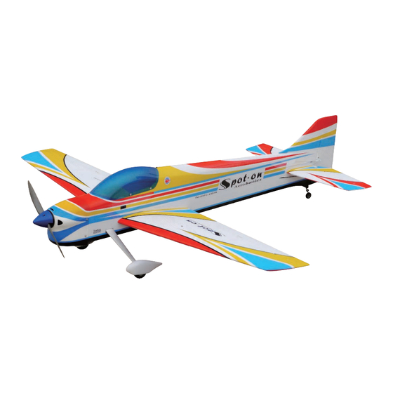
0.52-0.72 cu.in. displacement 4-stroke
Requires : 4-channel radio w / 5 standard servos
Wing Span
Wing Area
Flying Weight
Fuselage Length
Warning !This model is not a toy.
It is designed for maximum performance. Please seek advice if one is not familiar with this kind
of engine powered precision model. Operating this model without prior preparation may cause
injuries. Remember, safety is the most important thing. Always keep this instruction manual at
hand for quick reference.
The World Models
Manufacturing Co
w w w t h e w o r l d m o d e l s c o m
A249LPO27471203
Specifications
* Sp e cifica tio n s a re su b je ct to ch a n g e with o u t n o tice .*
LTD
.,
.
.
.
INSTRUCTION MANUAL
53.5 in / 1
36
0 mm
53 sq in / 34
8
.7
5. lb / 2
3
40
0 g
57
in / 1
450
mm
ALMOST-READY-TO-FLY (ARF) SERIES
(A249L)
sq dm
FACTORY PRE-FABRICATED
MADE IN CHINA
Advertisement

Related Manuals for THE WORLD MODELS Spot-On 50


Summary of Contents for THE WORLD MODELS Spot-On 50
- Page 1 Operating this model without prior preparation may cause injuries. Remember, safety is the most important thing. Always keep this instruction manual at hand for quick reference. FACTORY PRE-FABRICATED The World Models ALMOST-READY-TO-FLY (ARF) SERIES Manufacturing Co MADE IN CHINA...
- Page 2 INDEX BEFORE YOU BEGIN PARTS LIST ASSEMBLY P.3-P.11 SAFETY PRECAUTIONS P.11 BEFORE YOU BEGIN Read through the manual before you begin, so you will have an overall idea of what to do. Check all parts. If you find any defective or missing parts contact your local dealer. Please DRY FIT and check for defects for all parts that will require CA or Epoxy for final assembly.
- Page 3 Parts List 1. MAIN WING -- 1 pair 10. ENGINE MOUNT PL5111050 -- 1 set SOCKET HEAD SCREW M4x25mm -- 4 pcs 2. SCREW PB2x22mm -- 4 pcs WASHER d4.5xD9mm -- 4 pcs PUSHROD Ø1.8x80mm w/ Threads (For Aileron) -- 2 pcs CLEVIS PL4112103 -- 2 pcs 11.
- Page 4 Main Wing Apply instant type CA glue to both sides of each hinge. Aileron Servo Lead Bottom View Aileron Servo Pushrod Ø1.8x80mm PB2x22mm PB2x22mm Screw PWA2x8mm Screw Fuel Tube D6x5mm Clevis Ø1mm pilot holes for World Models tri-horn are pre-drilled. Horn Please look for pin-hole marks at under side of control surfaces.
- Page 5 Main Wing P le a s e a p p ly g lu e to a ll s u rfa c e s o f w in g tu b e . Wing Tube Ø16x285mm Make sure to glue securely. If not properly glued, a failure in fight may occur. Co m p le te d Stabilizer / Elevator * Also refer to step 18 Win g Settin g...
- Page 6 Vertical Fin & Rudder C =C ' Apply instant type CA glue to both sides of each hinge. Co m p leted Tail Landing Gear WHEEL Ø25mm PA3x12mm PA3x12mm Screw 2.1mm Collar 2.1mm Collar 3mm set screw 1.5mm Bottom View A249LPO27471203...
- Page 7 Elevator Pushrod Ø1mm pilot holes for World Models Tri-horn are pre-drilled. Please look for pin-hole marks at under side of control surfaces. PB2 x14mm Screw PB2x14mm Pushrod Ø1.4x730mm Fuel Tube Ø6 x5mm Clevis Horn TWM PL8210010 Bottom View CLEVIS WRENCH Rudder Pullwire Ø1mm pilot holes for World Models tri-horn are pre-drilled.
- Page 8 Inverted Mount Engine Mount Socket Head Screw M4x25mm Washer M4x25mm d4.5xD9mm Engine Mount PL5111050 d4.5xD9mm Washer Blind nuts are off-centered to keep the spinner at the fuselage axis. Fuel Tank Cable Tie 1.5x5x400mm Double-sided Tape 40x100mm Bottom View Completed Servo Set 3x 3mm Set Screw Set Screw 3x3mm...
- Page 9 Engine Socket Head Screw Installed Engine Position M3.5x30mm (Inverted Mount) M3.5 115mm 4.5 in. d3.5xD8mm Washer M3 .5 N ut d3 .5 x D 8 m m Wa s he r M3 .5x30mm Washer d3.5xD8mm Throttle Pushrod Ø1.2x480mm 3.5 30 Plastic Tube d2xD3x300mm Radio Equipment...
- Page 10 Main Wing HM4 x35mm Screw d4.2xD14.5mm Washer HM4 x35mm Washer d4.2xD14.5mm B o tto m View C an o p y First insert the grommet into the canopy then apply screw. Screw PWA2.3 X 8mm Double-sided Tape 900mm Silicon Grommet d1.5xD6.5mm d1.5 x D6.5 mm Silicon Grommet...
- Page 11 Wing Setting Adjust the wing and fuselage configuration as shown in the diagrams. A = A ' B = B ' C = C ' A249LPO27471203 P.10...
- Page 12 Adjust the control throws as shown in the diagram. Control Throws T hese throws are good for general flying. You can adjust according to your personal preference. Rudder 45mm 45mm Elevator 18mm 18mm Aileron 10mm 10mm T he ideal C.G. position is 117mm (4.6 in.) behind the leading edge measured at where the wing C.G.
- Page 13 LINKAGE CONNECTOR HW7111050 & HW7111060 Drill 2mm hole at servo horn. Insert linkage connector into servo horn. Make sure shoulder of screw is cleared from servo horn. Add washer to reduce play if necessary. Shoulder Tighten up the round nut against the shoulder.
- Page 14 Usage of the transparent 3D template This transparent 3D template is used for position guidance of the actual cutting of the pre-painted cowling. Simply cut the transparent 3D template to fit your engine and exhaust pipe, then slide onto the actual cowling and use as template to mark the openings required for final cutting.
- Page 15 Optional Parts Fuel Filler 180mm Extension Code No. Size Package Code No. Size Package PL8110030 15 x 22 x 49m m 1 x 1 pc KW0011800 180mm 1 set 180mm Y-Cord Code No. Size Package KW0021800 180mm 1 pc Clevis Wrench Code No.
- Page 16 The World Models Manufacturing Co., Ltd. www.theworldmodels.com A249LPO27471203...
Need help?
Do you have a question about the Spot-On 50 and is the answer not in the manual?
Questions and answers