Table of Contents
Advertisement
Quick Links
Advertisement
Table of Contents

Related Manuals for Dahua NVR6000 Series


Summary of Contents for Dahua NVR6000 Series
- Page 1 NVR Series User’s Manual Version 3.0.1...
-
Page 2: Table Of Contents
Table of Contents FEATURES AND SPECIFICATIONS ..............1 Overview ............................1 Features ............................1 Specifications ........................... 2 1.3.1 NVR 6000/6064 Series ....................... 2 1.3.2 NVR 724-256 Series ........................3 OVERVIEW AND CONTROLS ................6 Front Panel ............................6 2.1.1 NVR 60 Series ..........................6 2.1.2 NVR 724 Series ........................... - Page 3 Information ............................27 3.4.1 HDD Information ........................27 3.4.2 BPS............................. 29 3.4.3 Log .............................. 30 3.4.4 Version ............................31 3.4.5 Online Users ..........................31 3.4.6 Remote Device Information ...................... 32 3.4.7 System Status ..........................33 Setting ............................. 34 3.5.1 General ............................35 3.5.2 Encode ............................
- Page 4 WEB OPERATION .................... 81 General Introduction ........................81 5.1.1 Preparation..........................81 5.1.2 Log in ............................81 LAN Mode ............................82 Real-time Monitor ........................... 84 PTZ ..............................85 Image/Alarm out ..........................86 5.5.1 Image............................86 5.5.2 Alarm output ..........................87 WAN Login ............................. 87 Setup ...............................
- Page 5 APPENDIX H TOXIC OR HAZARDOUS MATERIALS OR ELEMENTS ....148...
- Page 6 Welcome Thank you for purchasing our NVR! This user’s manual is designed to be a reference tool for the installation and operation of your system. Here you can find information about this series NVR features and functions, as well as a detailed menu tree.
-
Page 7: Important Safeguards And Warnings
Important Safeguards and Warnings 1.Electrical safety All installation and operation here should conform to your local electrical safety codes. We assume no liability or responsibility for all the fires or electrical shock caused by improper handling or installation. 2.Transportation security Heavy stress, violent vibration or water splash are not allowed during transportation, storage and installation. -
Page 8: Features And Specifications
1 FEATURES AND SPECIFICATIONS 1.1 Overview This series product is designed for the management, storage and applications of high definition video data. It adopts the LINUX OS and professional customized hardware platform. It consists of several HDDs management systems, front-end high definition device management system, high definition analysis system, and large-capacity video storage system. -
Page 9: Specifications
Support to browse video and audio of the remote IPC and NVS. 1.3 Specifications 1.3.1 NVR 6000/6064 Series Specifications NVR6000 Series NVR6064 Series Main Processor Industrial X86 multiple-core processor Operation System Embedded LINUX system Power Support hot swap Redundant dual ball bearing fan MTBF>100 thousand hours... -
Page 10: Nvr 724-256 Series
Storage Humidity 5%~90%(Non-condense) Working Altitude -60m~3000m Dimensions 516.5mm(without length)×485mm(With ear)×133.2mm(L*W*H) Net Weight 20Kg (front panel:0.4Kg) Installation Mode Standard 19-inch rack installation 1.3.2 NVR 724-256 Series Specifications NVR724-256 Main Processor Industrial X86 multiple-core processor Operation System Embedded LINUX system Power Support hot swap Redundant dual ball bearing fan MTBF>100 thousand hours Support online replacement. - Page 11 Non-working HDD adopts hibernation function. It is suitable HDD Manager to guarantee sound ventilation, lower power consumption and enhance HDD life span. Manual recording, motion detection recording, schedule recording and alarm recording. Record Mode Priority: Manual recording>card numbe recording-> alarm recording>motion detection recording>schedule recording.
- Page 12 Support user /group and its corresponding rights modification. No limit to the user or group amount. Password modification Administrator can modify other user’s password. Password Account lock strategy Authentication Five times login failure in thirty minutes may result in account lock.
-
Page 13: Overview And Controls
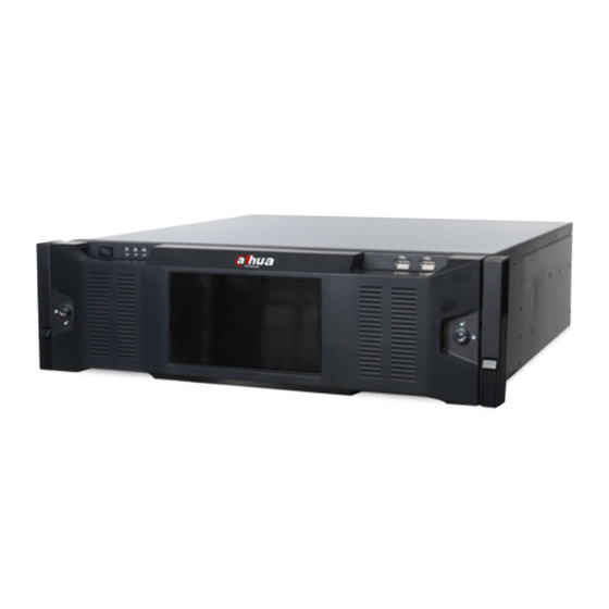
2 Overview and Controls This section provides information about the rear panel. When you install this series NVR for the first time, please refer to this part first. 2.1 Front Panel 2.1.1 NVR 60 Series For the product of LCD, the front panel is shown as below. See Figure 2-1. Figure 2-1 Please refer to the following sheet for detailed information. -
Page 14: Nvr 724 Series
Please refer to the following sheet for detailed information. Name Function Power button Press it once to turn on the device. Press it for a long time to turn off the device (Usually we do not recommend). Press power button for a long time or pull out the power cable may result in device auto restart. - Page 15 Figure 2-4 Icon Name Function Front panel lock USB port Network The network indicator light is blue and it flashes when indicator light you connect the device to the network. Alarm indicator The alarm indicator light becomes on once an alarm light occurred.
-
Page 16: Rear Panel
reading or writing the data. Figure 2-5 2.2 Rear Panel 2.2.1 NVR 60 Series The general rear panel is shown as in Figure 2-6. Figure 2-6 The redundant power series rear panel is shown as in Figure 2-7. Figure 2-7 Please refer to the following sheet for rear panel button information. -
Page 17: Nvr 74 Series
Function Function Power socket Video VGA output Audio Input eSATA port Audio output USB port Bidirectional talk input HDMI port Network port Alarm input, alarm output, RS485 port. Important Right now, system does not support audio input port. System supports HDMI1/HDMI2 port by default. -
Page 18: Alarm Input And Output Connection
Please refer to the following sheet for detailed information. Name Name Alarm input/alarm output HDMI port(Reserved port. Right now system does not support HD decode card.) Power port HDMI port eSATA port USB port SAS port Video VGA output Network port RS485 port Audio input port RS232(RS422)... - Page 19 Figure 2-10 Icon Note ALARM 1 to ALARM 16. The alarm becomes active in low voltage. 1,2,3,4,5,6, 7,8,9,10,11, 12,13,14,15,16 Eight groups of normal open activation output (on/off button) 1-ON C,2-ON C, 3-ON C,4-ON C, 5-ON C,6-ON C, 7-ON C,8-ON C GND cable.
-
Page 20: Alarm Input Port
Four groups of normal open activation output (on/off NO1 C1,NO2 C2,NO3 C3, button) NO4 C4 2.3.2 Alarm Input Port Please refer to the following sheet for more information. Normal open or Normal close type. Please parallel connect COM end and GND end of the alarm detector (Provide external power to the alarm detector). - Page 21 3ms max Length of close time Longevity Mechanical 50×106 times (3Hz) Electrical 200×103 times (0.5Hz) -40℃ ~+70℃ Temperature...
-
Page 22: Overview Of Navigation And Controls
3 Overview of Navigation and Controls Connect the device to the monitor and then connect a mouse and power cable. Click the power button at the front panel and then boot up the device to view the video output. You can use the mouse to implement some GUI operation. - Page 23 Preview control bar When you move your mouse on the top middle pane of the preview window, you can see the following preview control bar. See Figure 3-3. Figure 3-3 Please refer to the following sheet for detailed information. Main stream and extra stream Real-time monitor switch IPC bidirectional talk...
- Page 24 During the preview playback process, you can not see the channel title and record status of current channel. It will display the channel title and the record status once you exit the preview playback. During the preview playback, you can not switch the displayed channel or change current window-display mode.
- Page 25 Speed is to control PTZ movement speed. The value ranges from 1 to 8.The speed 8 is faster than speed 1. You can use the remote control to click the small keyboard to set. You can click of the zoom, focus and iris to zoom in/out, definition and brightness. The PTZ rotation supports 8 directions.
- Page 26 Figure 3-6, click page switch button, the interface is shown as in Figure 3-9. X328H328H328H Here you can activate the following functions: Preset Tour Pattern Auto scan Auto pan Flip Reset Page switch Figure 3-9 Note: ...
- Page 27 In Figure 3-8, click patrol button. The interface is shown as in Figure 3-11. Input preset number and add this preset to a patrol (tour). For each patrol (tour), you can input max 80 presets. Figure 3-11 Activate Patrol (tour) Figure 3-8, input patrol (tour) number in the No.
- Page 28 Activate Auto Scan In Figure 3-9, click “Auto Scan” button, the system begins auto scan. Correspondingly, the auto scan button becomes Stop button. Click stop button to terminate scan operation. Flip In Figure 3-9, click page switch button, you can see an interface is shown as below. See Figure 3-14.
-
Page 29: Main Menu
You can use the channel list and the device list to manage the connected remote device. The channel list is on the left. Here you can view all connected channel information. The green color in front of the camera name means current channel is recording now. The grey color means current channel is not recording. -
Page 30: Search & Playback
Figure 3-17 3.3 Search & Playback Click search button in the main menu, or you can right click mouse and then select the Search item. Search interface is shown as below. See Figure 3-18. Figure 3-18... - Page 31 Please refer to the following sheet for more information. Name Function Here is to display the searched picture or file. Display Support 1/4/9/16-window playback. window Here you can select to search extra stream, main stream or picture. Search Select play from read-write disk or play from thee peripheral devices. type The blue highlighted date means there is picture or file.
-
Page 32: Mark Playback
Smart search The volume of the playback Snapshot Right now, system does not support this function. It is to display the record type and its period in current search criteria. In 4-window playback mode, there are corresponding four time bars. In other playback mode, there is only one time bar. - Page 33 When you are playback record, you can mark the record when there is important information. After playback, you can use time or the mark key words to search corresponding record and then play. It is very easy for you to get the important video information. ...
-
Page 34: Information
Double click one mark information item, you can see system pops up a dialogue box for you to change mark information. You can only change mark name here. Delete Here you can check the mark information item you want to delete and then click Delete button, you can remove one mark item. - Page 35 Figure 3-22 In Figure 3-22, click view record d time button, HDD record time information interface is shown as in Figure 3-23. Figure 3-23 Parameter Function SATA 1-16: 1-16 here means current series product max supports 16 HDD Port HDDs. RAID:1-6 here means current series product max supports 6 SATA HDDs.
-
Page 36: Bps
RAID HDDs. The NVR724 series product max supports 24 SATA HDDs, 16 RAID HDDs. You can view the HDD amount the device connected to; ﹡ means the second HDD is current working HDD. Physical port It is to display device connected physical port. Type The corresponding HDD property. -
Page 37: Log
3.4.3 Log Here is for you to view system log file. System lists the following information. See Figure 3-25. Start time/end time: Pleased select start time and end time, then click search button. You can view the log files in a list. System max displays 100 logs in one page. It can max save 1024 log files. -
Page 38: Version
Figure 3-26 3.4.4 Version Here is for you to view some version information. See Figure 3-27. Please note the following interface is based on the 128-channel series product and it is for reference only. Channel Alarm in Alarm out ... -
Page 39: Remote Device Information
Here is for you manage online users connected to the local device. See Figure 3-28. You can disconnect one user or block one user if you have proper system right. Figure 3-28 3.4.6 Remote Device Information Here you can view the channel status of the remote device, connection log and network balance information and etc. -
Page 40: System Status
Figure 3-29 Connection log: In this interface, you can search the IPC log information of the corresponding channel. It includes IPC online, offline and etc. See Figure 3-30. Figure 3-30 Network Balance: Here you can view network data transmission speed, receive speed. See Figure 3-31. -
Page 41: Setting
Figure 3-32 Click RAID information, you can view RAID name, level, HDD information and etc. See Figure 3-33. Figure 3-33 3.5 Setting In main menu, highlight setting icon and double click mouse. System setting interface is shown as below. See Figure 3-34. -
Page 42: General
Figure 3-34 Important Please note you need to have the proper right to implement the following operation. 3.5.1 General General setting includes the following items. See Figure 3-35. System time: Here is for you to set system time Date format: There are three types: YYYYY-MM-DD: MM-DD-YYYYY or DD-MM-YYYY. - Page 43 Auto logout: Here is for you to set auto logout interval once login user remains inactive for a specified time. Value ranges from 0 to 60 minutes. Navigation bar: Check the box here, system displays the navigation bar on the interface. ...
-
Page 44: Encode
Figure 3-37 Figure 3-38 3.5.2 Encode Encode setting includes the following items. See Figure 3-39. Please note some series do not support extra stream. Channel: Select the channel you want. Type: Please select from the dropdown list. There are three options: regular/motion detect/alarm. - Page 45 Snapshot: Click snapshot button, you can set snapshot mode, picture size, quality and frequency. See Figure 3-40. Before the snapshot operation, please make sure the front- end device supports current operation. Snapshot mode: There are two modes: Timing (Schedule) and activation. If you set timing mode, you need to set snapshot frequency.
- Page 46 Figure 3-40 Figure 3-41 Figure 3-42...
-
Page 47: Schedule
Figure 3-43 3.5.3 Schedule In the main menu, from setting to schedule, you can go to schedule menu. See Figure 3-44. Channel: Please select the channel number first. You can select “all” if you want to set for the whole channels. ... -
Page 48: Network
Figure 3-44 Figure 3-45 3.5.3.1 Quick Setup Copy function allows you to copy one channel setup to another. After setting in channel 1, click Copy button, you can see current channel name is grey such as channel 1. Now you can select the channel you wan to paste such as channel 5/6/7. - Page 49 Load balance: In this mode, device uses bond0 to communicate with the ext ernal device. All cards are working now and bearing the network load. Their network load are general the same. The system is shown as offline once these cards are all offline. For IPv6, the IP address and the default gateway are left in blank.
- Page 50 Network setting interface is shown as in Figure 3-47. Please draw a circle to enable corresponding function and then double click current item to go to setup interface. Figure 3-47 3.5.4.2 IP Filter IP filter interface is shown as in Figure 3-48. You can add IP in the following list. System supports IPv4 and IPv6 both.
- Page 51 London GMT+0 Berlin GMT+1 Cairo GMT+2 Moscow GMT+3 New Deli GMT+5 Bangkok GMT+7 Beijing (Hong Kong) GMT+8 Tokyo GMT+9 Sydney GMT+10 Hawaii GMT-10 Alaska GMT-9 Pacific Time(P.T) GMT-8 American Mountain Time(M.T) GMT-7 American Central Time(C.T) GMT-6 American Eastern Time(E.T) GMT-5 Atlantic Time GMT-4 Brazil...
- Page 52 Reserved local multiple cast group address -224.0.0.0-224.0.0.255 -TTL=1 When sending out telegraph -For example 224.0.0.1 All systems in the sub-net 224.0.0.2 All routers in the sub-net 224.0.0.4 DVMRP router 224.0.0.5 OSPF router 224.0.0.13 PIMv2 router Administrative scoped addressees -239.0.0.0-239.255.255.255 -Private address space ...
- Page 53 In network DDNS, please select DDNS type and highlight enable item. And then please input your PPPoE name you get from you IPS and server IP (PC with DDNS). Click save button and then reboot system. Click save button, system prompts for rebooting to get all setup activated. After rebooting, open IE and input the domain name.
- Page 54 Except default domain name registration, you can also use customized domain name (You can input your self-defined domain name.) After successful registration, you can use domain name to login installed of the device IP. User name: It is optional. You can input your commonly used email address. Important ...
- Page 55 Figure 3-53 Figure 3-54 3.5.4.8 UPNP The UPNP protocol is to establish a mapping relationship between the LAN and the WAN. Please input the router IP address in the LAN in Figure 3-46. Double click the UPNP item in Figure 3-47, you can see the following interface. See Figure 3-53. ...
- Page 56 Internal port:Port that has been mapped in the router. External port:Port that has been mapped locally. Default: UPNP default port setting is the HTTP, TCP and UDP of the NVR. Add to the list: Click it to add the mapping relationship. ...
- Page 57 Sender: Please input sender email box here. Title: Please input email subject here. System support English character and Arabic number. Max 32-digit. Receiver: Please input receiver email address here. System max supports 3 email boxes. SSL enable: System supports SSL encryption box. ...
- Page 58 You need to download or buy FTP service tool (such as Ser-U FTP SERVER) to establish FTP service. Please install Ser-U FTP SERVER first. From “start” -> “program” -> Serv-U FTP Server -> Serv- U Administator. Now you can set user password and FTP folder. Please note you need to grant write right to FTP upload user.
- Page 59 File length is upload file length. When setup is larger than the actual file length, system will upload the whole file. When setup here is smaller than the actual file length, system only uploads the set length and auto ignore the left section. When interval value is 0, system uploads all corresponding files.
- Page 60 Figure 3-63 3.5.4.12 SNMP SNMP is an abbreviation of Simple Network Management Protocol. It provides the basic network management frame of the network management system. The SNMP widely used in many environments. It is used in many network device, software and system. You can set in the following interface.
- Page 61 In Figure 3-64, check the box to enable the SNMP function. Input the IP address of the PC than is running the software in the Trap address. You can use default setup for the rest items. Compile the above mentioned two MIB file via the software MIB Builder. ...
-
Page 62: Alarm
Cluster function: When the master device is malfunction the slave device can replace the master device setup and virtual IP to monitor and record. There is no risk of record loss and can guarantee proper real-time monitor function. After the master device resumed proper work, the slave device continue working until you fix manually via the WEB. - Page 63 PTZ activation: When an alarm occurred, system can activate the PTZ operation. The PTZ activation lasts an anti-dither period. In the Pan/Tilt/Zoom interface (Main menu->Setting-> Pan/Tilt/Zoom), please set video channel, speed dome protocol and etc. Select the channel of current speed dome as current monitor video and the right click mouse to select Pan/Tilt/Zoom item.
- Page 64 system begins the alarm record instead of the MD record if the local alarm and MD event occurred at the same time. Tour: Here you can enable tour function when alarm occurs. System supports 1/8-window tour. Please go to chapter 3.5.7 Display for tour interval setup. Please note the tour setup here has higher priority than the tour setup you set in the Display interface.
-
Page 65: Detect
Figure 3-69 Figure 3-70 3.5.6 Detect Go to Detect Menu In the main menu, from Setting to Detect, you can see motion detect interface. See Figure 3-71.There is three detection types: motion detection, video loss, camera masking. The video loss has no detection region and sensitivity setup and camera masking has no detection region setup. - Page 66 mode, you can click the direction buttons to move the green rectangle to set the motion detection zone. After you completed the setup, right click mouse to exit current setup. Do remember click save button to save current setup. If you click ESC button to exit the region setup interface system will not save your zone setup.
- Page 67 Figure 3-71 Figure 3-72 Figure 3-73...
- Page 68 Figure 3-74 Figure 3-75 Video Loss In Figure 3-71, select video loss from the type list. You can see the interface is shown as in Figure 3-76.This function allows you to be informed when video loss phenomenon occurred. You can enable alarm output channel and then enable show message function. Tips: You can enable preset/tour/pattern activation operation when video loss occurs.
-
Page 69: Display
Camera Masking When someone viciously masks the lens, or the output video is in one-color due to the environments light change, the system can alert you to guarantee video continuity. Camera masking interface is shown as in Figure 3-77. You can enable alarm output channel and then enable show message function. - Page 70 process, you can use mouse or click Shift to turn on window switch function. Stands for opening switch function, stands for closing switch function. Monitor tour type: System support 1-window tour. Alarm tour type: System support 1-window tour. ...
-
Page 71: Default
In tour mode, you can see the following interface. On the right corner, right click mouse, you can control the tour. There are two icons: stands for enabling window switch and stands for disabling window function. See Figure 3-80. Figure 3-80 3.5.8 Default Click default icon, system pops up a dialogue box. -
Page 72: Remote Device
System menu color, language, time display mode, video format, IP address, user account will not maintain previous setup after default operation! 3.6 Remote Device In the main menu, click the Remote Device icon to go to the corresponding interface. The remote device interface is shown as in Figure 3-82. ... -
Page 73: Advanced
8mbps. The delay time of each channel is below 500ms. This series product supports the IPC from many popular manufactures such as Sony, Hitachi, Axis, Samsung, and Dahua. Figure 3-84 3.7 Advanced Double click advanced icon in the main window, the interface is shown as below. -
Page 74: Hdd Manager
3.7.1 HDD Manager Here is for you to view and implement hard disk management. See Figure 3-86. You can see current HDD type, status, capacity and record time. When HDD is working properly, system is shown as O. When HDD error occurred, system is shown as X. ... -
Page 75: Abnormality
Figure 3-87 Important HDD group here refers to the HDD port number it does not change in case you replace the HDD. HDD Channel Setting Click the button named with “Channel Setting” in Figure 3-86, system will pop up an interface shown as in Figure 3-88. -
Page 76: Alarm Output
Abnormality interface is shown as in Figure 3-89. Event type: There are several options for you such as disk error, no disk, disconnection, IP conflict, MAC conflict, redundant power and etc. Alarm output: Please select alarm activation output port (multiple choices). ... -
Page 77: Manual Record
3.7.4 Manual Record Note: You need to have proper rights to implement the following operations. Please make sure the HDD has been properly installed. 3.7.4.1 Manual record menu Right click mouse on the preview mode or in the main menu, from Advanced->Manual Record, you can see manual record menu is shown as in Figure 3-91. - Page 78 3.7.4.4 Enable all channel recording Highlight ○ below All, you can enable all channel recording. All channel schedule record Please highlight “ALL” after “Schedule”. See Figure 3-93. When system is in schedule recording, all channels will record as you have previously set (Main menu->Setting->Schedule).
-
Page 79: Account
Figure 3-95 3.7.5 Account Here is for you to implement account management. See Figure 3-96. Here you can: Add new user Modify user Add group Modify group Modify password. For account management please note: For the user account name and the user group, the string max length is 6-byte. - Page 80 Figure 3-96 3.7.5.1 Modify Password Click password button, the interface is shown as in Figure 3-97. Here you can modify account password. Please select the account from the dropdown list, input the old password and then input the new password twice. Click the Save button to confirm current modification. For the users of user account right, it can modify password of other users.
-
Page 81: Auto Maintain
Figure 3-98 3.7.5.3 Add/Modify User Click add user button, the interface is shown as in Figure 3-99. Please input the user name, password, select the group it belongs to from the dropdown list. Then you can check the corresponding rights for current user. For convenient user management, usually we recommend the general user right is lower than the admin account. -
Page 82: Config Backup
Figure 3-100 3.7.7 Config Backup The configuration file backup interface is shown as below. See Figure 3-101. This function allows you to copy current system configuration to other devices or import configuration from USB devices. . Figure 3-101 3.7.8 RAID Manager This interface is for you to manage RAID disk, display RAID name, type, free space, total space, status and etc. -
Page 83: Backup
Figure 3-102 Click Hotspare manager button in Figure 3-102, you can go to the following interface to add or delete hotspare disk. See Figure 3-103. Figure 3-103 3.8 Backup In this interface, you can backup record file to the USB device. Connect USB burner, USB device, or portable HDD and etc to the device. - Page 84 Figure 3-104 Select backup device and click Backup button to go to the backup interface. Click Browse button, you can view folders of connected device. Set channel, file start time and end time. Click add button, system begins search. All matched files are listed below.
-
Page 85: Shutdown
If there is any error during the backup process such as there is no backup device, you can see the corresponding dialogue box. The file name format usually is: Channel number+Record type+Time. In the file name, the YDM format is Y+M+D+H+M+S. File extension name is .dav. 3.9 Shutdown Double click shutdown button, system pops up a dialogue box for you to select. - Page 86 Figure 3-107...
-
Page 87: System Upgrade
4 System Upgrade There are two ways for you to update the NVR: you can use update tool of the Windows or the flash drive. Please visit our website or contact our technical engineer to get the update tool for Windows. You can use REC upgrade or ConfigTool. -
Page 88: Web Operation
5 WEB OPERATION 5.1 General Introduction The device web provides channel monitor menu tree, search, alarm setup, system setup, PTZ control and monitor window. 5.1.1 Preparation Before log in, please make sure: PC and NVR connection is OK. You have set PC IP address, NVR IP address, subnet mask and gateway. -
Page 89: Lan Mode
Figure 5-2 IE Safety Setup After installation, the interface is shown as below. See Figure 5-1. Please input your user name and password. Default factory name is admin and password is admin. Note: For security reasons, please modify your password after you first login. Figure 5-1 5.2 LAN Mode For the LAN mode, after you logged in, you can see the main window. - Page 90 Figure 5-2 This main window can be divided into the following sections. Section 1: there are five function buttons: Live(chapter 5.3), setup (chapter 5.7), info (chapter 5.8) , playback (chapter 5.9), alarm (chapter 5.10), and logout (chapter 5.11). Section 2: There are connected channel numbers.
-
Page 91: Real-Time Monitor
Section 4: Instant record button. Click it, the button becomes yellow and system begins manual record. See Figure 5-5. Click it again, system restores previous record mode. Figure 5-5 Section 5: Local play button. The Web can playback the saved (Extension name is dav) files in the PC-end. Click local play button, system pops up the following interface for you to select local play file. -
Page 92: Ptz
3 4 5 Figure 5-8 1: Digital zoom: Click this button and then left drag the mouse in the zone to zoom in. right click mouse system restores original status. 2: Local record. When you click local record button, the system begins recording and this button becomes highlighted. -
Page 93: Image/Alarm Out
Parameter Function You can turn on or turn off the light/wiper. Light and wiper 3D Intelligent Positioning You can click this icon to display or hide the PTZ control platform. Figure 5-9 5.5 Image/Alarm out Select one monitor channel video and then click Image button in section 8, the interface is shown as Figure 5-10. -
Page 94: Alarm Output
Figure 5-10 5.5.2 Alarm output Here you can enable or disable the alarm signal of the corresponding port. See Figure 5-11. Figure 5-11 5.6 WAN Login In WAN mode, after you logged in, the interface is shown as below. See Figure 5-12. - Page 95 Figure 5-12 Please refer to the following contents for LAN and WAN login difference. 1) In the WAN mode, system opens the main stream of the first channel to monitor by default. The open/close button on the left pane is null. 2) You can select different channels and different monitor modes at the bottom of the interface.
-
Page 96: Setup
Important The window display mode and the channel number are by default. For example, for the 16- channel, the max window split mode is 16. 3) Multiple-channel monitor, system adopts extra stream to monitor by default. Double click one channel, system switches to single channel and system uses main stream to monitor. You can view there are two icons at the left top corner of the channel number for you reference. - Page 97 Figure 5-15 Please refer to the following sheet for log parameter information. Parameter Function Click Device search button, you can view the searched device Device information on the list. It includes device IP address, port, device search name, manufacturer and type. Select a device in the list and then click Add button, system can connect the device automatically and add it to the Added device list.
- Page 98 Note: System supports manufactures such as Panasonic, Sony, Dynacolor, Samsung, AXIS, Arecont, Dahua and Onvif standard protocol. If you do not input IP address here. System uses default IP 192.168.0.0 and system does not connect to this IP.
- Page 99 The larger the number is , the bright the video is. When you input the value here, the bright section and the dark section of the video will be adjusted accordingly. You can use this function when the whole video is too dark or too bright. Please note the video may become hazy if the value is too high.
- Page 100 It is to disable the BLC function. Please note this function is disabled by default. Profile It is to set the white balance mode. It has effect on the general hue of the video. This function is on by default. You can select the different scene mode such as auto, sunny, cloudy, home, office, night, disable and etc to adjust the video to the best quality.
- Page 101 Parameter Function Channel Please select a channel from the dropdown list. Video enable Check the box here to enable extra stream video. This item is enabled by default. Code stream It includes main stream, motion stream and alarm stream. You type can select different encode frame rates form different recorded events.
- Page 102 Figure 5-18 Please refer to the following sheet for detailed information. Parameter Function There are two modes: Regular (schedule) and Trigger. Snapshot type Regular snapshot is valid during the specified period you set. Trigger snapshot only is valid when motion detect alarm, tampering alarm or local activation alarm occurs.
- Page 103 Figure 5-19 Please refer to the following sheet for detailed information. Parameter Function Cover-area Check Preview or Monitor first. Click Set button, you can privacy mask the specified video in the preview or monitor video. System max supports 4 privacy mask zones. Time Title You can enable this function so that system overlays time ...
- Page 104 Figure 5-20 5.7.1.4 Channel Name Here you can set channel name. See Figure 5-21. Figure 5-21...
-
Page 105: Network
5.7.1.5 IPC Upgrade Here you can upgrade network camera. See Figure 5-21. Select a network camera you want to upgrade and then click browse button to select upgrade file. Click start upgrade button to begin upgrade process. You can see the corresponding dialogue box after the upgrade is finish. - Page 106 Figure 5-23 Figure 5-24 Please refer to the following sheet for detailed information. Parameter Function Network Mode It includes multiple address, fault tolerance, and load balancing. Multiple-address mode: eth1 and eth2 and etc operate separately (Max support 4 network ports). You can use the services such as HTTP, RTP service via eth1/2/3/4.
- Page 107 as DHCP, email, FTP and etc. Network fault-tolerance: In this mode, device uses bond0 to communicate with the external devices. You can focus on one host IP address. At the same time, you need to set one master card. Usually there is only one running card (master card).System can enable alternate card when the master card is malfunction.
- Page 108 Figure 5-25 Please refer to the following sheet for detailed information. Parameter Function Max connection It is the max Web connection for the same device. The value ranges from 1 to 120. The default setup is 120. TCP port The default value is 37777. You can input the actual port number if necessary.
- Page 109 Figure 5-26 5.7.2.4 DDNS The DDNS interface is shown as in Figure 5-27. The DDNS is to set to connect the various servers so that you can access the system via the server. Please go to the corresponding service website to apply a domain name and then access the system via the domain.
- Page 110 Parameter Function Password The password you input to log in the server. Update period Device sends out alive signal to the server regularly. You can set interval value between the device and DDNS server here. Quick DDNS and Client-end Introduction 1) Background Introduction Device IP is not fixed if you use ADSL to login the network.
- Page 111 Figure 5-28 5.7.2.6 Email The email interface is shown as in Figure 5-29. Figure 5-29 Please refer to the following sheet for detailed information. Parameter Function Please check the box here to enable email function. Enable Input server address and then enable this function. SMTP Server Port Default value is 25.
- Page 112 Parameter Function Anonymity For the server supports the anonymity function. You can auto login anonymously. You do not need to input the user name. password and the sender information. The user name of the sender email account. User Name The password of sender email account. Password Sender email address.
- Page 113 Figure 5-30 5.7.2.8 SNMP The SNMP interface is shown as in Figure 5-31. The SNMP allows the communication between the network management work station software and the proxy of the managed device. It is reserved for the 3 party to develop. Figure 5-31 Please refer to the following sheet for detailed information.
- Page 114 Parameter Function and the proxy are the same. The read community will read all the objects the SNMP supported in the specified name. The default setup is public. It is a string. It is a command between the manage process Write Community and the proxy process.
- Page 115 Figure 5-33 5.7.2.11 Alarm Centre The alarm centre interface is shown as below. See Figure 5-34. This interface is reserved for you to develop. System can upload alarm signal to the alarm centre when local alarm occurs. Before you use alarm centre, please set server IP, port and etc. When an alarm occurs, system can send out data as the protocol defined, so the client-end can get the data.
- Page 116 Figure 5-35 5.7.2.12.1 Create Server Certificate If it is your first time to use this function, please follow the steps listed below. In Figure 5-35, click button, input country name, state name and etc. Click Create button. See Figure 5-36. Note Please make sure the IP or domain information is the same as your device IP or domain name.
- Page 117 Figure 5-38 Click Open button, you can go to the following interface. See Figure 5-39. Figure 5-39 Click Install certificate button, you can go to certificate wizard. See Figure 5-40.
- Page 118 Figure 5-40 Click Next button to continue. Now you can select a location for the certificate. See Figure 5-41. Figure 5-41 Click Next button, you can see the certificate import process is complete. See Figure 5-42.
- Page 119 Figure 5-42 Click Finish button, you can see system pops up a security warning dialogue box. See Figure 5-43. Figure 5-43 Click Yes button, system pops up the following dialogue box, you can see the certificate download is complete. See Figure 5-44. Figure 5-44 5.7.2.12.3 View and set HTTPS port From Setup->Network->Connection, you can see the following interface.
- Page 120 Figure 5-45 5.7.2.12.4 Login Open the browser and then input https://xx.xx.xx.xx:port. xx.xx.xx.xx: is your device IP or domain mane. Port is your HTTPS port. If you are using default HTTPS value 443, you do not need to add port information here. You can input https://xx.xx.xx.xx to access. Now you can see the login interface if your setup is right.
-
Page 121: Event
Parameter Function Port ISCSI server port. Default setup is 3260. Path It is to set remote path. Click browse button to select. Note Each path is a iSCSI share disk. The path is already there when you create on the server. After you set server IP, port, user name, password and path, click Add button to add new information on the list. - Page 122 Figure 5-48 Figure 5-49...
- Page 123 Figure 5-50 Figure 5-51...
- Page 124 Figure 5-52 Please refer to the following sheet for detailed information. Parameter Function Enable You need to check the box to enable motion detection function. Please select a channel from the dropdown list. Period Motion detection function becomes activated in the specified ...
- Page 125 Parameter Function Show System can pop up a message to alarm you in the local host message screen if you enabled this function. Buzzer Check the box here to enable this function. The buzzer beeps when an alarm occurs. Alarm upload System can upload the alarm signal to the centre (Including alarm centre.
- Page 126 After analysis video, system can generate a video loss alarm when the detected moving signal reached the sensitivity you set here. Please note video loss does not support anti-dither, sensitivity, region setup. For rest setups, please refer to chapter 5.7.3.1.1 motion detect for detailed information. Figure 5-53 5.7.3.1.3 Tampering The tampering interface is shown as in Figure 5-54.
- Page 127 5.7.3.2 Alarm Before operation, please make sure you have properly connected alarm devices such as buzzer. The input mode includes local alarm and network alarm. 5.7.3.2.1 Local Alarm The local alarm interface is shown as in Figure 5-55. It refers to alarm from the local device. Figure 5-55 Figure 5-56...
- Page 128 Figure 5-57 Please refer to the following sheet for detailed information. Parameter Function Enable You need to check the box to enable this function. Please select a channel from the dropdown list. Period This function becomes activated in the specified ...
- Page 129 Parameter Function Show message System can pop up a message to alarm you in the local host screen if you enabled this function. Buzzer Check the box here to enable this function. The buzzer beeps when an alarm occurs. Alarm upload System can upload the alarm signal to the centre (Including alarm centre).
- Page 130 Figure 5-58 5.7.3.2.3 IPC Offline Alarm The IPC offline alarm interface is shown as in Figure 5-59. For detailed information, please refer to chapter 5.7.3.2.1. Figure 5-59...
- Page 131 5.7.3.3 Abnormality It includes seven statuses: No disk, disk error, disk no space, net disconnection, IP conflict and MAC conflict and power fault. See Figure 5-60 through Figure 5-66. Figure 5-60 Figure 5-61 Figure 5-62 Figure 5-63 Figure 5-64...
-
Page 132: Storage
Figure 5-65 Figure 5-66 Please refer to the following sheet for detailed information. Parameter Function Event The abnormal events include: No disk, disk error, disk no space, net Type disconnection, IP conflict, MAC conflict and power fault. You can set one or more items here. Less than: You can set the minimum percentage value here (For disk ... - Page 133 Figure 5-67 Figure 5-68...
- Page 134 Figure 5-69 Please refer to the following sheet for detailed information. Parameter Function Channel Please select a channel from the dropdown list. Pre-record Please input pre-record time here. The value ranges from 0 to 30. Redundancy Check the box here to enable redundancy function. Please note this function is null if there is only one HDD.
- Page 135 Parameter Function Copy function allows you to copy one channel setup to another. After Copy setting in channel, click Copy button, you can go to interface Figure 5-69. You can see current channel name is grey such as channel 1. Now you can select the channel you wan to paste such as channel 5/6/7.
- Page 136 Figure 5-72 5.7.4.3 Manual Record The interface is shown as in Figure 5-73. Figure 5-73 Please refer to the following sheet for detailed information. Parameter Function Here you can view channel number. Channel The number displayed here is the max channel amount of your device.
-
Page 137: Setting
Status There are three statuses: schedule, manual and stop. System enables auto record function as you set in record schedule Schedule setup (general, motion detect and alarm). It has the highest priority. Manual Enable corresponding channel to record no matter what period applied in the record setup. - Page 138 The general interface is shown as in Figure 5-76. Figure 5-76 Please refer to the following sheet for detailed information. Parameter Function It is to set device name. Device ID Device No. It is device channel number. Language You can select the language from the dropdown list. Please note the device needs to reboot to get the modification activated.
- Page 139 Figure 5-77 Please refer to the following sheet for detailed information. Parameter Function Here you can select date format from the dropdown list. Date format There are two options: 24-H and 12-H. Time Format The time zone of the device. Time zone It is to set system time.
- Page 140 Here you can click Add box to add a new holiday and then click Save button to save. Figure 5-78 5.7.5.2 Account Note: For the character in the following user name or the user group name, system max supports 6-digits.
- Page 141 Figure 5-79 Add user: It is to add a name to group and set the user rights. See Figure 5-80. There are four default users: admin/888888/666666 and hidden user “default”. Except user 6666, other users have administrator right. The user 666666 can only have the monitor rights,. Hidden user “default”...
- Page 142 Modify user It is to modify the user property, belonging group, password and rights. See Figure 5-81. Modify password It is to modify the user password. You need to input the old password and then input the new password twice to confirm the new setup. Please click the OK button to save. Please note, the password ranges from 1-digit to 6-digit.
- Page 143 Add group: It is to add group and set its corresponding rights. See Figure 5-83. Please input the group name and then check the box to select the corresponding rights. It includes: shutdown/reboot device, live view, record control, PTZ control and etc. Figure 5-83 Modify group Click the modify group button, you can see an interface is shown as in Figure 5-84.
- Page 144 Figure 5-85 Please refer to the following sheet for detailed information. Parameter Function Output format System supports HDMI1+HDMI2. It is to select output screen No. Screen No. There are four options: 1920×1080, 1280×1024(default), Resolution 1280×720, 1024×768. Please note the system needs to reboot to activate new setup.
- Page 145 Figure 5-86 5.7.5.5 Default Figure 5-87 The default setup interface is shown as in Here you can select Network/Event/Storage/Setting/Remote device. Or you can check the All box to select all items. Figure 5-87 5.7.5.6 Import/Export The interface is shown as in Figure 5-88. Figure 5-88 Please refer to the following sheet for detailed information.
- Page 146 Parameter Function It is to import the local setup files to the system. Import It is to export the corresponding WEB setup to your local PC. Export 5.7.5.7 Auto maintenance The auto maintenance interface is shown as in Figure 5-89. Here you can select auto reboot and auto delete old files interval from the dropdown list.
-
Page 147: Information
Figure 5-91 5.8 Information 5.8.1 Version The version interface is shown as in Figure 5-92. Here you can view record channel, alarm input/output information, software version, release date and etc. Please note the following information is for reference only. Figure 5-92 5.8.2 Log Here you can view system log. -
Page 148: Online User
Figure 5-93 Please refer to the following sheet for log parameter information. Parameter Function Log types include: system operation, configuration operation, data Type operation, event operation, record operation, user management, log clear. Set the start time of the requested log. Start time Set the end time of the requested log. -
Page 149: Hdd Info
5.8.4 HDD Info It is to view HDD information. See Figure 5-95. Figure 5-95 5.9 Playback Click Playback button, you can see an interface is shown as in Figure 5-96. Please set record type, record date, window display mode and channel name. You can click the date on the right pane to select the date. - Page 150 Figure 5-97 Select a file you want to play and then click Play button, system can begin playback. You can select to playback in full-screen. Please note for one channel, system can not playback and download at the same time. You can use the playback control bar to implement various operations such as play, pause, stop, slow play, fast play and etc.
- Page 151 Figure 5-98 Load more It is for you to search record or picture. You can select record channel, record type and record time to download. See Figure 5-99.
- Page 152 Figure 5-99 Remote backup In Figure 5-99, there is a remote back pane at the left bottom of the pane. It allows you to backup the record or picture to your local USB storage media via the Web remotely. Click the search button;...
-
Page 153: Alarm
Now you can see system begins backup and the Stop backup button becomes valid. You can click it to terminate current operation. At the bottom of the interface, there is a process bar for your reference. Watermark Please select a file and then click Verify button to see the file has been tampered with or not 5.10 Alarm Click alarm function, you can see an interface is shown as Figure 5-101. -
Page 154: Log Out
5.11 Log out Click log out button, system goes back to log in interface. See Figure 5-102. You need to input user name and password to login again. Figure 5-102... -
Page 155: Appendix H Toxic Or Hazardous Materials Or Elements
Appendix H Toxic or Hazardous Materials or Elements Toxic or Hazardous Materials or Elements Component Name Cr VI PBDE Sheet ○ ○ ○ ○ ○ ○ Metal(Case) Plastic Parts ○ ○ ○ ○ ○ ○ (Panel) ○ ○ ○ ○ ○...
Need help?
Do you have a question about the NVR6000 Series and is the answer not in the manual?
Questions and answers