Table of Contents
Advertisement
Electron Multiplier CCD Camera
Instruction Manual
•
CAUTION
HAMAMATSU PHOTONICS K.K.
C9100-02
Thank you for your purchase.
Follow the safety precautions in Chapter 1 in order to avoid
personal injury and damage to property when using this camera.
The manual describes the correct handling method of C9100
camera and provides cautions in order to avoid accidents. Read
this manual carefully beforehand use the camera correctly.
After reading the manual, store it in a location where you can
refer to it at any time.
Ver. 1.7
April 2007
7825172-07
Advertisement
Table of Contents

Related Manuals for Hamamatsu Photonics C9100-02


Summary of Contents for Hamamatsu Photonics C9100-02
-
Page 1: Instruction Manual
Read this manual carefully beforehand use the camera correctly. After reading the manual, store it in a location where you can refer to it at any time. Ver. 1.7 April 2007 HAMAMATSU PHOTONICS K.K. 7825172-07... - Page 2 ~ Blank page ~...
-
Page 3: Safety Precautions
C9100-02 Ver.1.7 1. SAFETY PRECAUTIONS CLASSIFICATION OF WARNINGS We have classified the warning symbols that appear in this operating manual and on the camera as follows for better comprehension of their meaning. Make sure that you fully understand them and obey the instructions they contain. - Page 4 C9100-02 Ver.1.7 WARNING Power supply Use the camera with the voltage indicated on the rating. Using a different voltage can damage the camera and lead to fire or electric shock. Cables Be careful not to place heavy objects on cables or bend it excessively.
- Page 5 C9100-02 Ver.1.7 CAUTION Connecting and disconnecting cables Always turn off the power before connecting and disconnecting cables. Affixing the camera When fitting the camera to a tripod or other fixture, use the screw (1/4-20UNC) in the center of a camera mount or the threaded sleeve (M3) about the mount's perimeter.
-
Page 6: Check The Contents Of Package
Hamamatsu subsidiary or local distributor without attempting to operate the camera. C9100-02 camera Lens mount cap (attached to the camera) Camera mount C9100-02 instruction manual (this booklet) [Option] AC adaptor A3472-07 (The accessories: Power supply Cord) Camera cable (5 m) -
Page 7: Table Of Contents
C9100-02 Ver.1.7 1. SAFETY PRECAUTIONS................1 CLASSIFICATION OF WARNINGS ..............1 2. CHECK THE CONTENTS OF PACKAGE........... 4 3. INSTALLATION................... 4 4. OVERVIEW....................7 5. FEATURES....................7 6. NAME AND FUNCTION OF THE PARTS ........... 8 CAMERA ......................8 7. CONNECTING CABLES ................10 8. - Page 8 C9100-02 Ver.1.7 14-1 CAMERA ......................26 15. WARRANTY ....................27 16. CONTACT INFORMATION ............... 28...
-
Page 9: Overview
5. FEATURES (1) High Gain C9100-02 can amplify the electric charge with approximately 2000 times on the CCD chip and they can detect the objects that the general normal CCD cameras have not and offer the images with real time. -
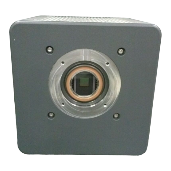
Page 10: Name And Function Of The Parts
C9100-02 Ver.1.7 6. NAME AND FUNCTION OF THE PARTS CAMERA ③ ④ ⑤ ① ② ③ ⑥ ⑦ Fig.6-1 ① Lens mount C-mount lens or optical system with C-mount can be attached. • C-mount has a depth of 7 mm. Screwing the lens too far into Note the camera may scratch the glass surface. - Page 11 C9100-02 Ver.1.7 ⑥ Mode switching switch This is a switch for the camera maintenance. • All positions are set to “OFF”. Do not change this. ⑦ CameraLink interface connector [DIGITAL OUT] Connector used for connecting the camera to the CameraLink interface board.
-
Page 12: Connecting Cables
C9100-02 Ver.1.7 7. CONNECTING CABLES Refer to the figure below when connecting the various cables. ③ Power supply cord AC adaptor A3472-07 (Option) Camera ① Camera cable (Option) ② CameraLink interface cable (Option) CameraLink interface board Fig.7-1 • When cables are connected, confirming the power switch is in the OFF position. -
Page 13: Operation
C9100-02 Ver.1.7 8. OPERATION PREPARATION FOR IMAGING Use the following procedure when starting operating of the camera. (1) Connect the equipment as shown in Figure 7-1 before operating of the camera. (2) Switch the AC adaptor's power switch to ON. -
Page 14: Image Acquisition
C9100-02 Ver.1.7 9. IMAGE ACQUISITION This section describes the modes required when using the camera to obtain images. OVERVIEW OF THE CAMERA MODES This camera features many different operational modes. Furthermore, all modes involve the CameraLink interface's built-in microprocessor, providing control and setting for all modes. -
Page 15: Precautions When Using The Ccd
C9100-02 Ver.1.7 10. PRECAUTIONS WHEN USING THE CCD C9100 uses a CCD. Read the following points regarding handling of the CCD carefully. (1) White spots During long exposure times, imperfection in the CCD’s silicon wafer cause white spots to be generated on the image. As of the present time, there is no workaround for this phenomenon. -
Page 16: Maintenance
C9100-02 Ver.1.7 11. MAINTENANCE 11-1 CARE Clean the exterior with a soft, dry cloth. • Do not use a wet cloth, dirty cloth. -
Page 17: Troubleshooting Checklist
C9100-02 Ver.1.7 12. TROUBLESHOOTING CHECKLIST If an abnormality occurs, look up the possible causes in the following tables and, if necessary, report the details to Hamamatsu subsidiary or local distributor. 12-1 IMAGES NOT TRANSFERRED Cause Measures Chapter Cables not fully connected. -
Page 18: Specifications
C9100-02 Ver.1.7 13. SPECIFICATIONS 13-1 CAMERA SPECIFICATIONS (1) Electrical Specifications Camera head type Hermetic vacuum-sealed air-cooled head Imaging device Frame transfer CCD Effective number of pixels 1000 × 1000 Cell size 8.0 µm × 8.0 µm Effective area 8.0 mm ×... - Page 19 C9100-02 Ver.1.7 (3) Operating environment Ambient operating temperature 0 ºC to + 40 ºC Ambient storage temperature -10 ºC to + 50 ºC Ambient operating humidity 70 % or less (no condensation) Operating space Indoor, altitude up to 2000 m...
-
Page 20: Spectral Response Characteristics
C9100-02 Ver.1.7 13-2 SPECTRAL RESPONSE CHARACTERISTICS Following is the typical spectral characteristics of the CCD. C9100-02 Typical Spectral Response characteristic 1000 1100 Wave Length (nm) 13-3 EM GAIN Following is the setting value of SENSITIVITY and the typical EM gain. -
Page 21: Cameralink Interface Specifications
C9100-02 Ver.1.7 13-4 CAMERALINK INTERFACE SPECIFICATIONS CameraLink interface is a standard of a digital interface for industrial application standardized by digital camera manufactures and frame grabber board manufactures. 28 bits digital data (TX0 to TX27) can be transferred as being changed into 5 signals (X0, X1, X2, X3 and XCLK) by parallel serial transformation. - Page 22 C9100-02 Ver.1.7 (2) CameraLink bit assignments 28 bit Solution Pin Name Input Signal Name DB10 TX10 TX11 TX12 DB11 TX13 DB12 TX14 DB13 TX15 TX16 TX17 TX18 TX19 TX20 TX21 TX22 TX23 Spare TX24 LVAL TX25 FVAL TX26 DVAL TX27 ●...
-
Page 23: Timing I/O Specifications
C9100-02 Ver.1.7 13-5 TIMING I/O SPECIFICATIONS 13-5-1 TIMING I/O CONNECTOR PIN ASSIGNMENTS [TIMING I/O] C9100 uses Hirose model HR10A-7R-6S connector for input and output signals. Signal Pin connections Trigger In Digital GND N.C. N.C. Integ Out HR10A-7R-6S Digital GND ● Trigger In : Input pin of the external trigger pulse. -
Page 24: Trigger In Timings
C9100-02 Ver.1.7 13-5-2 TRIGGER IN TIMINGS Input the external trigger pulse when the camera is operated in External Control mode. The signal level is TTL level or C-MOS 3.3 V level (Termination is 680 Ω), and the external trigger pulse polarity can be set either to negative or positive. Minimum trigger pulse width is 1 µs in edge trigger mode and synchronous readout trigger mode or 100 µs in level trigger mode. - Page 25 C9100-02 Ver.1.7 (2) Level trigger mode (pulse polarity is negative) Trigger In cycle > Exposure time + Readout time Trigger In cycle Over 100 µs Trigger In Within 64 µs Exposure Exposure Exposure Readout Readout Exposure time + Readout time In level trigger mode, exposure time is set by width of Trigger In.
-
Page 26: Integ Out Timings
C9100-02 Ver.1.7 (3) Synchronous Readout trigger mode (pulse polarity is negative) Readout starts when Trigger In pulse is detected. The exposure time is defined as the time span of Trigger In pulses. The first pulse is ignored when this trigger mode is selected. -
Page 27: Power Specifications
C9100-02 Ver.1.7 13-6 POWER SPECIFICATIONS ・ Connector (D-SUB 15 pin) ・ Product No. DA-15PF-T-N ・ Maker [C9100 Series Pin Assignment] Name Specs. +12V (Camera) Current 2.0 A (max.), Ripple peak to peak ± 60 mV (max.) N.C. N.C. N.C. +12V (Peltier) Current 5.0 A (max.), Ripple peak to peak ±... -
Page 28: Dimensional Outline
C9100-02 Ver.1.7 14. DIMENSIONAL OUTLINE 14-1 CAMERA (Unit: mm) 130 1 8.45 123 2 ± ± 21 1 80 0.5 ± ± 1- 32UN C- MOUNT D= 5 2X4- M D= 5... -
Page 29: Warranty
If Hamamatsu Photonics consider the problem to be a malfunction, we will decide whether dispatch an engineer or have the camera returned to us for... -
Page 30: Contact Information
The contents of this manual are subject to change without notice. The unauthorized reproduction or distribution of parts or all of this manual is prohibited. If one of the following problems occurs, please contact Hamamatsu Photonics. (See the CONTACT INFORMATION.) We will deal with the problem immediately.
Need help?
Do you have a question about the C9100-02 and is the answer not in the manual?
Questions and answers