Table of Contents
Advertisement
Quick Links
Advertisement
Table of Contents

Subscribe to Our Youtube Channel
Related Manuals for Hamamatsu Photonics c2400


Summary of Contents for Hamamatsu Photonics c2400
- Page 1 Artisan Technology Group is your source for quality new and certified-used/pre-owned equipment SERVICE CENTER REPAIRS WE BUY USED EQUIPMENT • FAST SHIPPING AND DELIVERY Experienced engineers and technicians on staff Sell your excess, underutilized, and idle used equipment at our full-service, in-house repair center We also offer credit for buy-backs and trade-ins •...
- Page 2 VIDEO CAMERA FOR MICROSCOPY C2400 INSTRUCTION MANUAL...
-
Page 3: Table Of Contents
CONTENTS • Section 1. I n t r o d u c t i o n Section 2. F e a t u r e s 2-1 C o n t r a s t Enhancement Circuit 2-2 T i m i n g Control by Crystal Oscillation 2-3 L e v e l Indicator 2-4 T u b e Protection Circuit 2-5 W h i t e Clipper... - Page 4 1. INTRODUCTION The C2400 is a compact, 2-piece, high performance video camera system designed specifically for microscopy and quantitative electronic imaging. The system utilizes the very latest technology to achieve exceptionally high quality images ideally suited for both analog and digital processing. The system is composed of a lightweight camera head and separate camera control unit.
-
Page 5: C O N T R A S T Enhancement Circuit
External SYNC enables the synchronization of C2400 scanning 2 . 1 0 E x t e r n a l S Y N C w i t h other equipment by supplying HD and VD signals to the C2400. (Option M2505) -
Page 6: Operational Video Output
For applications in which a non-composite video signal is required, the 2.11 Operational camera is easily configured to provide this. This operational video output signal does not include a synchronizing signal and is therefore DC in Video Output nature with the black level defined at 0 volts. The standard camera cable is 3 meters in length. - Page 7 3. SYSTEM COMPONENTS Camera Head Camera Control Unit Camera Cable TV MONITOR Cable (BNC-M) GROUND Cable Spare Fuse V 1 A ) 1 Instruction Manual...
- Page 8 4. SPECIFICATIONS Electrical Input Voltage AC 100/117/220/240 ± 1 0 % (50/60 Hz) Power Consumption 70 VA nominal 60 Hz, EIA RS-170 Vertical Sweep Rate 50 Hz, CCIR System B 15.750 KHz, EIA RS-170 Horizontal Sweep Rate 15.625 KHz, CCIR System Lines per frame 525, EIA RS-170 625, CCIR System B...
- Page 9 5. PERFORMANCE Geometric Stability Less than 0.2 % (10-40° C) Geometric Distortion Less than 1 % (2 % for -03, 3 % for -08) Signal to Noise Greater than 45 dB pp/RMS (Greater than 40 dB for -03 and -08) Video Bandwidth 0 - 1 0 MHz or greater 1 - 1 0 times...
-
Page 10: U N P A C K I N G
6. INSTALLATION unpack the equipment, and see that all system components 6.1 U n p a c k i n g d e s c r i b e d in Section 3 of this manual are secure and undamaged. installing the equipment, attention should be paid to the following 6.2 Installation Site points: 1. -
Page 11: I N S T A L L A T I O N Of Camera Head
6.4 C a b l e Connection CAMERA HEAD CAMERA CABLE CAMERA CONTROL UNIT VIDEO OUT CAMERA LINE LINE ( t 2 C POWER CABLE GROUND CABLE TV MONITOR CABLE TV MONITOR LINE... - Page 12 (1) C a m e r a Cable Insert the male connector of the camera cable into the female re- ceptacle at the rear of the CCU and the female connector of the cable to the camera head. Tighten the threaded rings around the connector.
-
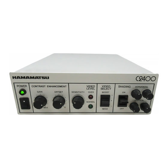
Page 13: Section 7. L O C A T I O N And Function Of Controls
7. LOCATION AND FUNCTION OF CONTROLS FRONT PANEL: H A I M I A P A A T S U POWER VIDEO VIDEO SHADING H O R I Z O N T A L C O N T R A S T E N H A N C E M E N T LEVEL SELECT •... - Page 14 ® SENSITIVITY * Effective only with the C2400-00,-03 and -08 camera heads. This control adjusts the sensitivity of the tube. Turn this control clockwise and the sensitivity of the tube will be increased.
- Page 15 OUT 1 unless the CCU is configured for Operational Video Output, in which case, this terminal outputs operational video signals in- stead of composite signals. 0 H D This terminal normally outputs HD (Horizontal Drive) signal. When the M2505 EXTERNAL SYNC option is installed this terminal be- comes an HD signal input.
-
Page 16: A D J U S T M E N T Of Video Level 1
8. OPERATION Confirm that all cables are properly connected. (Refer to Section 8.1 P r e l i m i n a r y for cable connection.) A d j u s t m e n t s ( 2 ) Preset each control on the front panel as specified below: (a) Turn the GAIN control knob fully counterclockwise. -
Page 17: A D J U S T M E N T Of Contrast Enhancement 1
Adjustment of Video Level * * For -08 Camera Head This imaging tube employs a intensifier with adjustable voltage. Increasing this voltage increases the sensitivity accordingly. The best quality image is obtained when the SENSITIVITY control is turned to its minimum position. Increased voltage results in a poorer S/N, therefore, the SENSITIVITY control should be increased only when the imaging system cannot supply enough illumination or it is in- tentionally desired to reduce object illumination. -
Page 18: D E O Select
brighter. Turning the adjusting screw counterclockwise results in Adjustment o f S h a d i n g the corners becoming brighter. Corrector (OPTION) 4. Ve r t i c a l Sawtooth i ' , . Adjusting vertical sawtooth decreases the difference in intensity between the top and bottom of the image. -
Page 19: C C U Cleaning
9. MAINTENANCE AND TROUBLESHOOTING the inside of the ccu is not normally required. However, should 9.1 C C U C l e a n i n g t h e CCU be exposed to abnormally dusty conditions, clean the inside of the CCU periodically, as follows: 1. -
Page 20: Troubleshooting 1
9.3 C 2 4 0 0 TROUBLESHOOTING CHART No image on the TV monitor Are the pilot lamps of the CCU and TV monitor on? Are the video Out of the CCU and the video In of the TV monitor properly connected? Are the CCU and the TV camera head properly connected? Is the OFFSET potentiometer on the front panel turned fully clockwise? -
Page 21: Section 10. O P T I O N Installation Instructions
10. OPTION INSTALLATION INSTRUCTIONS The SHADING CORRECTOR option comes completely adjusted and 10.1 M2502 ready for use. SHADING Installation: CORRECTOR 1. Tu r n POWER switch OFF on the Camera Control Unit (CCU). 2. U n p l u g the CCU power supply cord. 3. - Page 22 M2502 S H A D I N G C O R - a d j u s t i n g screw clockwise results in the left side of the image be- RECTOR brighter. Turning the adjusting screw counterclockwise results in the right side of the image becoming brighter. 3.
- Page 23 M2503 VIDEO BOOSTER Installation: 1. Turn POWER switch OFF on the Camera Control Unit (CCU). 2. Unplug the CCU power supply cord. 3. Using a small Phillips screwdriver, loosen the 4 screws on the sides of the CCU and remove the cover. 4.
- Page 24 M2503 VIDEO BOOSTER C a l i b r a t i o n : 1. Plug the Power Supply cord of the CCU into AC outlet. 2. Tu r n on the power to the CCU. The following waveforms should be shown on the oscilloscope display screen.
-
Page 25: M2503 Video Booster
5. U s i n g the OFS potentiometer, adjust the OFFSET to make the 0 volt M2503 VIDEO BOOSTER level of Channel 1 a n d Channel 2 identical. Turning the OFS po- tentiometer determines the 0 volt D C level o f the characteristic, turning clockwise results in the level decreasing, counterclockwise increasing. - Page 26 . • 7 . . 1111 0 . . • • .111111 _ . 1 1 1 1 . - ..1 1 1 1 1 1 • d d • • a M • •111/ .
-
Page 27: M2505 External Sync
In this position (lower), the output video signal is inverted with regard 1 0 . 3 M 2 5 0 4 V I D E O t o input intensity as indicated below. INVERTER Inversion The VIDEO INVERTER option comes completely adjusted and ready for use. - Page 28 Vertical Delay time of the picture from the front edge of the VD signal. EIA RS170 H (16 Horizontal time) CCIR SYSTEM B 2 5 . 5 H (25.5 Horizontal time) Termination resistance is normally 75 0. For conditions requiring greater termination resistance, consult your authorized C2400 representative.
- Page 29 1 0 . 5 O P E R A T I O N A L O U T 2 and non-composite in nature. Illustrated below is the OP VIDEO V I D E O O U T P U T w a v e f o r m compared to the C2400 composite signal. For modification details consult your authorized C2400 camera representative.
- Page 30 Artisan Technology Group is your source for quality new and certified-used/pre-owned equipment SERVICE CENTER REPAIRS WE BUY USED EQUIPMENT • FAST SHIPPING AND DELIVERY Experienced engineers and technicians on staff Sell your excess, underutilized, and idle used equipment at our full-service, in-house repair center We also offer credit for buy-backs and trade-ins •...
Need help?
Do you have a question about the c2400 and is the answer not in the manual?
Questions and answers