Viking VCFF136D Service Manual
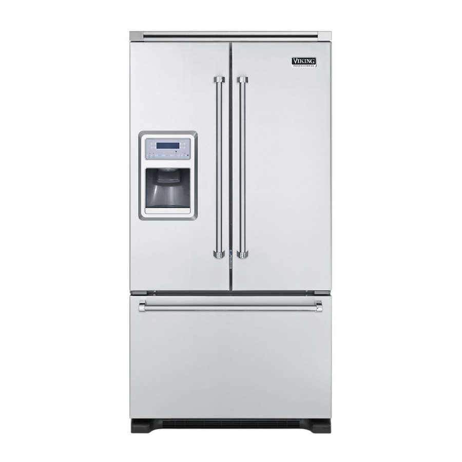
Freestanding french door bottom-mount refrigerator/ freezer with dispenser
Hide thumbs
Also See for VCFF136D:
- Installation manual (10 pages) ,
- Product brochure (56 pages) ,
- Specifications (5 pages)
Table of Contents
Advertisement
Service
Manual
This manual is to be used by qualified appliance technicians only.
Viking does not assume any responsibility for property damage
or personal injury for improper service procedures done by an
unqualified person.
Freestanding
French Door
Bottom-Mount
Refrigerator/
Freezer with
Dispenser
Preferred Service
This Base Manual covers general and
specific information including, but not
limited to the following models:
VCFF136D
DDFF136D
SMR-0011
February, 2011
Advertisement
Table of Contents

Subscribe to Our Youtube Channel
Related Manuals for Viking VCFF136D


Summary of Contents for Viking VCFF136D
- Page 1 Service Preferred Service Manual This manual is to be used by qualified appliance technicians only. Viking does not assume any responsibility for property damage or personal injury for improper service procedures done by an unqualified person. Freestanding French Door This Base Manual covers general and Bottom-Mount specific information including, but not...
-
Page 2: Table Of Contents
182 Keypad Operation ..........32 Troubleshooting ............73 192 Ice Maker State Test .......... 33 WIRING DIAGRAMS 193 Ice Maker Relay ..........33 Full Schematic ............76 201 Mullion Heater Override ........33 Wiring Diagram ............77 © 2010 Viking Preferred Service... -
Page 3: Important Information
“DANGER”, “WARNING” or “CAUTION”. These words mean: CAUTION DANGER VIKING will not be responsible for any injury Immediate hazards which WILL result in severe or property damage from improper service personal injury or death. procedures. If performing service on your... -
Page 4: Warranty Information
(2) years from the date of original retail purchase. Viking Range Corporation, warrantor, agrees to repair or replace, at its option, any part which fails or is found to be defective during the warranty period. -
Page 5: Warranty Service Information
The return of the Owner Registration Card is not a condition of warranty coverage. You should, however, return the Owner Registration Card so that Viking Range Corporation can contact you should any question of safety arise which could affect you. -
Page 6: General Information
( 9 0 8 ” 2 ” 2 ” - 1 / - 1 / ( 5 9 ( 5 9 2 ” 2 ” - 1 / - 1 / ( 6 6 ( 6 6 © 2010 Viking Preferred Service... -
Page 7: Warnings
Failure to follow these instructions can result in wall receptacle. DO NOT use an extension cord. death, fire, or electrical shock. WARNING BURN HAZARD DO NOT touch condenser coils near defrost pan. Doing so can result in burns. © 2010 Viking Preferred Service... -
Page 8: Model - Serial Number Matrix
ASSEMBLED IN USA 1665 TYPE BMA200 5.25 oz R134a VCFF136DSSO 148 g de R134a MOD# 115VAC/60Hz KO3028017 10.00 A SER# CODE 2213 ENERGY VERIFIED PERFORMANCE MINIMUM INSTALLATION CLEARANCE TOP-1/4 INCH EEV109900 ESPACE DE DEGAGEMENT REQUIS-1/4 © 2010 Viking Preferred Service... -
Page 9: Operation
firm. the refrigerator or freezer, first check the air vents to be sure they are not blocked before adjusting the controls. © 2010 Viking Preferred Service... -
Page 10: Adjusting Controls
3. Press the touch pad next to “SABBATH IS OFF” to switch between ON and OFF. Press the touch pad next to “DONE” to lock in the desired setting and return to the main menu. © 2010 Viking Preferred Service... - Page 11 2. Press the touch pad next to “HUMID CTRL IS ON” to switch between ON and OFF. Press the touch pad next to “Done” to lock in the desired setting and return to the main menu. © 2010 Viking Preferred Service...
-
Page 12: User Settings
The control, located on the right of the drawer, regulates the air temperature inside the drawer. Set control to “COLD” to provide normal refrigerator temperature. Use the “COLDEST” setting for meats or other deli items. © 2010 Viking Preferred Service... - Page 13 Note: After five minutes of continuous dispensing, the dispenser will stop dispensing water to avoid flooding. To continue dispensing, remove the container and press the dispensing lever again. © 2010 Viking Preferred Service...
-
Page 14: Water And Ice Dispenser
The indicator light will illuminate when Lock is on. Press and hold the “LOCKED” touch pad again for three seconds to unlock dispenser. The indicator light will turn OFF. © 2010 Viking Preferred Service... -
Page 15: Water Filtration System
Replacing the Water Filter corner of the refrigerator compartment. Replacement water filters are available through your local Viking Range Dealer. You may also order Note: DO NOT use with water that is filters by calling 1-888-845-4641 or online at microbiologically unsafe or of unknown quality vikingrange.com... -
Page 16: Cleaning
If you need to clean the condenser: the grille, the open areas behind the grille and the front surface area of the condenser. 5. Plug in refrigerator or reconnect power. © 2010 Viking Preferred Service... -
Page 17: Diagnostics
Note: Press only the touch pads next to your selection on the display screen, not the screen itself. Entering Programming Mode 1. Press and hold the “WATER” button. Press and Hold 2. Then press and hold the “LL” button. Both buttons are now being held in. Press and Hold Hold © 2010 Viking Preferred Service... - Page 18 These four numbers are the current programming code for this unit. The example below shows code 2213. Note: There is a DOT under the first number. This will be explained later Press © 2010 Viking Preferred Service...
- Page 19 8. As mentioned before, the first digit has a dot below it. This indicates that the First digit is in programming mode. Using either the UR or LR buttons, this digit can be changed from 0-9. Press either button to scroll through the numbers until the proper number is in the display © 2010 Viking Preferred Service...
- Page 20 Press and Hold Hold 11. To EXIT the programming mode, press and hold the “WATER” button for three seconds. If not depressed, it will automatically exit after 4 minutes.. © 2010 Viking Preferred Service...
-
Page 21: Defrost Operation
2. Then press and hold the “LR” button. Both buttons are now being held in. Press and Hold Hold 3. While still holding the LR button, release the “WATER” button and wait 3 seconds. Hold Release © 2010 Viking Preferred Service... - Page 22 5. Press the “LR” button again. Sh appears in right side of the display. Press 6. Press “LR” again to force defrost. Press 7. Fd and Sh will flash in display indicating unit is in defrost. © 2010 Viking Preferred Service...
-
Page 23: Entering Service Test Mode
2. Then press and hold the “UR” button. Both buttons are now being held in. Press and Hold Hold 3. While still holding the UR button, release the “WATER” button and wait 3 seconds. Hold Release 4. The display will show SE confirming entry in the Service Mode. © 2010 Viking Preferred Service... - Page 24 6. Display will show 101 in left display and OFF in the right display. Note: At any time to exit service test mode, open and close both refrigerator doors or hold door alarm for three seconds. © 2010 Viking Preferred Service...
-
Page 25: Service Tests
OFF, test cycles High or Low speed Note: Display will show 11.0-14.0 volts for HIGH and 7.75-8.25 volts for LOW. When off 0.0 will be displayed. © 2010 Viking Preferred Service... -
Page 26: Ice Compartment Fan
131 Mullion Heater Press the “UR” keypad or “LR” keypad to toggle Mullion Heater Off and On. Press either Press either button to button to toggle through cycle Mullion test cycles Heater ON or OFF © 2010 Viking Preferred Service... -
Page 27: Fresh Food Thermistor
This test will check the temperature from the outside temperate thermistor. You will see the actual temperature, OP open thermistor, or SH shorted thermistor. Press either button to toggle through Actual temperature test cycles outside the unit © 2010 Viking Preferred Service... -
Page 28: Ice Box Thermistor
CL (closed). Press either button to toggle through test cycles Note: By pushing freezer door switch you can toggle state from OP (open) to CL (closed). © 2010 Viking Preferred Service... -
Page 29: Disable Internal Lights
This test shows the state of the external ice chute door CL (closed) or OP (open). Press either button to toggle through test cycles Note: By pushing actuator pad you can control state of external ice chute door. © 2010 Viking Preferred Service... -
Page 30: Dispenser Lamp
Note: By pushing actuator pad you can control state of the ice auger motor and the internal ice chute door. 171 Actuator Pad Display shows the state of the actuator pad (On or OFF). Press either button to toggle through test cycles © 2010 Viking Preferred Service... -
Page 31: Actuator Pad
Display shows the state of the dispenser switch (ON or OFF). Press either button to toggle through test cycles Note: By pushing actuator pad or easy fill keypad you can change state of dispenser switch. © 2010 Viking Preferred Service... -
Page 32: Led Indicator Operation
This will test the keypad of the display. Press either button to toggle through test cycles Press Press Press Press Press Press Note: UR and LR keypads have no effect when pressed and UL and LL keypads remain operational. © 2010 Viking Preferred Service... -
Page 33: Ice Maker State Test
OFF cycle. When set to ON, the heater will operate 100% of the time. Press either Press either button to button to toggle through cycle mullion test cycles heater On (100%) or OFF (compressor off o © 2010 Viking Preferred Service... -
Page 34: Default Defrost Operation
Press either button to button to change toggle through calibration of freezer test cycles temperature plus or minus in 1˚ increments Note: Temperature will read in fahrenheit regardless of what current temperature scale is being used. © 2010 Viking Preferred Service... -
Page 35: Ice Compartment Temperature Offsets
(dEF) 231 Water Filter Usage Display shows the percent water filter consumption since water filter was reset. 100% indicates the filter should be replaced. Press either button to toggle through test cycles © 2010 Viking Preferred Service... -
Page 36: Water Filter Days In Use
Note: Test mode 301 and above are reserved for engineering use only. Note: At any time to exit service test mode, open and close both refrigerator doors or hold door alarm for three seconds. © 2010 Viking Preferred Service... -
Page 37: Service Diagnostics And Procedures
(J2) (J1) Connector Connector (J1) (J3) Connector Connector 12 volts/GND 12-volt power to power out to components dispenser mullion heaters and Main Control (J4) (J5) Connector User Interface Connector 12 volt power to dispenser components © 2010 Viking Preferred Service... -
Page 38: Component Testing Control Board
J3-4 (White/Black) to J3-5 (White/Orange) 9.31K @ room temperature Freezer Thermistor Control J3-2 (White/Yellow) to J3-5 (White/Orange) 9.38K Refrigerator Thermistor Control J3-1 (White/Blue) to J3-5 (White/Orange) 7.63K Ice Fan Control J6-2 (Red/Black) to J6-4(Blue/Black) 26.8K © 2010 Viking Preferred Service... -
Page 39: Component Testing Dispenser Board
Door Motor Switch Dispenser J4-4 (Yellow) to J4-5 (White) 0 door open door closed Mullion Element Dispenser J3-1(Red/ Black) to J3-3 (Blue/White) 14.3 Actuator Switch Dispenser J4-5 (White) to J4-6 (Orange) at rest 0 actuator pressed © 2010 Viking Preferred Service... -
Page 40: Main Control Board Wiring Connections
Orange damper switch J2-4 Damper switch Blue/Red J1-3 Not Used (for 120 volt fan) Black J2-3 Icemaker Yellow J1-2 Defrost thermostat Brown J2-1 Icemaker switch Gray J1-1 Condenser motor and Blue J2-1 Light Tan/Red compressor © 2010 Viking Preferred Service... -
Page 41: Dispenser Board Wiring Connections
J1-2 Fresh food thermistor Red/Black J3-3 Mullion Heater Blue/White J1-4 Freezer thermistor Yellow/Black J1-5 Ground Black/Green J4-1 +12VDC J4-2 Blue J4-3 Door Motor Black J4-4 Door Switch Yellow J4-5 Neutral White J4-6 Actuator Switch Orange © 2010 Viking Preferred Service... -
Page 42: Parts Location-Refrigerator
Service Diagnostics and Procedures Parts Location–Refrigerator Damper Fresh Food Themistor Ice Maker Water Filter Water Valve Light Assembly Water Valve Light Switch Auger Assembly Water Tank Meat/Vegetable Temperature Control © 2010 Viking Preferred Service... -
Page 43: Water Filter
1. Open fresh food door, depress securing tabs securing light cover and gently pull down cover. Light Housing Wiring 4. Replace or repair as necessary. 5. Reverse procedure to reinstall. Tabs 2. Replace light bulb. © 2010 Viking Preferred Service... -
Page 44: Refrigerator Temperature Sensor
3. Rotate right tray guide to disengage clip, then remove temperature control and right tray guide. Clip Temperature Sensor 7.63K ohms 4. Replace or repair as necessary. 5. Reverse procedure to reinstall. 4. Repair or replace as necessary. © 2010 Viking Preferred Service... -
Page 45: Water Tank
Water Line Water Tank Cover (lower) Water Tank Water Line 3. Press tabs and remove upper water tank cover. 5. Repair or replace water tank. 6. Reverse procedure to reinstall. Tabs Water Tank Cover (upper) © 2010 Viking Preferred Service... -
Page 46: Water Valve
If ok, replace Ground Wire module. Water Line to Dispenser Wiring Harness Ice Maker Water Line Front Module to Ice Maker 4. Repair or replace water valve. Adjustment 5. Reverse procedure to reinstall. Screw © 2010 Viking Preferred Service... -
Page 47: Water Flow
Service Diagnostics and Procedures–Disassembly Water Flow Water Inlet to Dispenser Water Filter Water Inlet to Water Solenoid Ice Maker Ice Maker and Dispenser Water Tank to Ice Maker and Dispenser Water Line © 2010 Viking Preferred Service... -
Page 48: Refrigerator Light Switch
4. Repair or replace switch. 3. Repair or replace ice bin/auger assembly. 5. Reverse procedure to reinstall. Note: Ice bin assembly individual parts are not serviceable. If assembly is damaged entire unit must be replaced. © 2010 Viking Preferred Service... -
Page 49: Ice Maker
It will Screwdriver be necessary to manually close the freezer door switch for some troubleshooting steps. Ensure that the shut-off arm is down and instruct customer on its use if necessary. © 2010 Viking Preferred Service... - Page 50 Slide ice maker forward to remove. Off/On Switch Note: while sliding assembly out tuck harness Repair or replace ice maker. against cabinet wall to prevent connector from jamming and preventing assembly removal. Reverse procedure to reinstall. © 2010 Viking Preferred Service...
- Page 51 Once the ice maker begins to turn, remove the jumper. With power present, verify 0VAC between test points T and H. If 120 volts is read, the Thermostat is open (this verifies the thermostat has closed). © 2010 Viking Preferred Service...
-
Page 52: Thermal Cut Out (Tco)
1. Green/Yellow 7. White 13. White 2. Yellow/Red 8. White 14. Red/Black 3. Blue/Red 9. Red 15. Violet 4. Tan 10. (Empty) 16. Blue/Black 5. Yellow 11. White 17. Black/Green 6. Gray 12. Red/Black 18. Pink © 2010 Viking Preferred Service... - Page 53 5. Remove fan blade from shaft. 7. From rear of assembly, remove rubber grommet. Fan motor is accessible. Fan Blade Auger Fan Motor Grommet 8. Repair or replace fan motor. 9. Reverse procedure to reinstall. © 2010 Viking Preferred Service...
-
Page 54: Auger Motor
3. Turn ice maker over. Remove screws securing auger motor and ice maker yoke. Screw Ice Maker Yoke Note: Ice maker yoke is left-handed thread. 4. Disconnect wiring. 6. Repair or replace auger motor. 7. Reverse procedure to reinstall. © 2010 Viking Preferred Service... -
Page 55: Auger Motor Solenoid
2. Remove wiring to motorized damper and to solenoid. Screwdriver Blade 3. Remove wiring harness and clip from housing. 5. Slide motorized damper forward to remove. Motorized Damper Wiring Harness Clip 6. Repair or replace motorized damper. 7. Reverse procedure to reinstall. © 2010 Viking Preferred Service... -
Page 56: Refrigerator Damper
2. Remove ice fan assembly, (see ice fan assembly section steps 1-3, page 52). 3. Slide damper out of housing and disconnect wiring harness. Wiring Harness Damper 4. Replace or repair as necessary. 5. Reverse procedure to reinstall. © 2010 Viking Preferred Service... -
Page 57: Parts Location-Freezer
Service Diagnostics and Procedures–Disassembly Parts Location–Freezer Light Assembly Freezer Thermistor Light Switch Evaporator Fan Rear Panel © 2010 Viking Preferred Service... -
Page 58: Freezer Drawer Switch
3. Pull switch into freezer compartment and disconnect wiring. To access light housing: 1. Remove freezer light bulb (see freezer light bulbs section above). 2. Press tabs securing light housing. Tabs 4. Repair or replace switch. 5. Reverse procedure to reinstall. © 2010 Viking Preferred Service... -
Page 59: Upper Freezer Bin
1. Open freezer drawer fully. Wiring 2. Press the tabs on each side of upper bins. 4. Replace or repair as necessary. 5. Reverse procedure to reinstall. 3. Remove upper bins. 4. Reverse procedure to reinstall. © 2010 Viking Preferred Service... -
Page 60: Freezer Door And Rail Assembly
3. Remove securing screws and left and right glide adapters. Screw Screw 3. Pull door, drawer slides, lower bins, upper and lower glide assemblies forward to remove. 4. Reverse procedure to reinstall. 4. Reverse procedure to reinstall. © 2010 Viking Preferred Service... -
Page 61: Freezer Thermistor
3. Remove left and right glide adapters (see glide adapter section, page 60). 4. Remove thermistor cover from evaporator cover. Wiring Evaporator Cover Thermistor Cover 8. Repair or replace thermistor. 9. Reverse procedure to reinstall. 5. Remove thermistor from thermistor cover. Thermistor © 2010 Viking Preferred Service... -
Page 62: Evaporator Cover
Evaporator Fan Cover 6. Remove securing screws and evaporator cover. Screw Screw With the evaporator cover removed, the evaporator fan, the freezer thermistor, defrost heater, and defrost thermostat are accessible. 7. Reverse procedure to reinstall. © 2010 Viking Preferred Service... -
Page 63: Defrost Heater
4. Remove thermistor cover (see freezer thermistor Evaporator Fan section, page 61). 5. Remove evaporator cover (see evaporator cover section, page 62). 6. Remove securing screws. Wiring 7. Repair or replace fan. 8. Reverse procedure to reinstall. Screw Screw © 2010 Viking Preferred Service... - Page 64 7. Pull evaporator assembly forward to release 9. Release clips to remove heater. from rear wall connectors. Connector Connector Clip 8. Disconnect wiring on both ends of heater. 10. Repair or replace defrost heater. 11. Reverse procedure to reinstall. Wiring Wiring © 2010 Viking Preferred Service...
-
Page 65: Defrost Thermostat
(see freezer door and rail assembly section, page 60). 3. Remove left and right glide adapters (see glide adapter section, page 60). 4. Remove evaporator cover (see evaporator cover section, page 61). 5. Disconnect wiring and un-clip thermostat. Defrost Thermostat © 2010 Viking Preferred Service... -
Page 66: Parts Location-Dispenser
Service Diagnostics and Procedures–Disassembly Parts Location–Dispenser User Interface Eschutcheon Tube Ring Lower Cover Ice Chute Grille Assembly © 2010 Viking Preferred Service... -
Page 67: Dispenser And User Interface
Dispenser and User Interface 1. Remove lower cover and grille. 3. Lift up and slide eschutcheon out. Eschutcheon Lower Cover Grille 2. Remove screws securing eschutcheon. 4. Disconnect wiring from dispenser board. Eschutcheon Screw Eschutcheon © 2010 Viking Preferred Service... -
Page 68: Ice Chute Assembly
Dispenser Board Eschutcheon Tube Ring 6. Repair or replace dispenser board. 7. Reverse procedure to reinstall. 3. Disengage dispenser tube from ice chute assembly, remove grounding screw and securing screws. Screw Ground Screw Dispenser Tube © 2010 Viking Preferred Service... -
Page 69: Ice Chute Wiring Connections
4. From the back of ice chute assembly, press clips Rear View to remove wiring harness. Clip Switch 5. Remove ice chute. Front View To Switch To Motor 6. Repair or replace ice chute. 7. Reverse procedure to reinstall. © 2010 Viking Preferred Service... -
Page 70: Parts Location-Rear
Service Diagnostics and Procedures–Disassembly Parts Location–Rear Control Board Condenser Overload Relay © 2010 Viking Preferred Service... -
Page 71: Main Control Board
1. Remove securing screws and outer control control board. board cover. Tabs Screw 2. Lift off the clear control board cover. Clear Cover 4. Repair or replace main control board. 5. Reverse procedure to reinstall. © 2010 Viking Preferred Service... -
Page 72: Overload Relay
Condenser Fan 2. Remove metal clip, disconnect wiring and remove relay from bracket. Overload Relay Repair or replace condenser fan. Reverse procedure to reinstall. Bracket 3. Repair or replace overload relay. 4. Reverse procedure to reinstall. © 2010 Viking Preferred Service... -
Page 73: Troubleshooting
Look for obstruction in valve Verify valve operation Clogged water valve Water valve Replace water valve Insufficient water to ice Restriction in supply line Remove restriction maker (with correct fill Water Valve Repair or replace water valve time) © 2010 Viking Preferred Service... - Page 74 Verify closure, replace if needed Dirty condenser Clean condenser coil Condenser fan Verify operation and no obstructions Control board Verify operation Defrost heater Verify operation Thermistor Verify operation Freezer too cold No continuity Determine discontinuity by tracing power © 2010 Viking Preferred Service...
- Page 75 Replace ice maker working Won’t cycle test with Ice maker Refer to ice maker test procedures (page 51) power available Won’t eject ice with power Ice maker Refer to ice maker test procedures (page 51) available © 2010 Viking Preferred Service...
-
Page 76: Full Schematic
Wiring and Schematics Full Schematic © 2010 Viking Preferred Service... -
Page 77: Wiring Diagram
Wiring and Schematics Wiring Diagram © 2010 Viking Preferred Service...
Need help?
Do you have a question about the VCFF136D and is the answer not in the manual?
Questions and answers
Are the fridge thermistor and the freezer thermistor the same part number?