JUMO LOGOSCREEN Operating Instructions Manual
Paperless recorder with tft display and compactflash card
Hide thumbs
Also See for LOGOSCREEN:
- Operating manual (136 pages) ,
- Operating instructions manual (68 pages)
Table of Contents
Advertisement
Quick Links
Download this manual
See also:
Operating Manual
Advertisement
Table of Contents

Related Manuals for JUMO LOGOSCREEN


Summary of Contents for JUMO LOGOSCREEN
- Page 1 J LOGOSCREEN nt Paperless Recorder with TFT display and CompactFlash card B 70.6580.1 Operating Instructions 08.06/00453819...
- Page 2 Menu structure of the paperless recorder v Device manager, Chapter 7, Page 51 v Memory manager, Chapter 6, Page 47 v Alarm and event lists, Chapter 5, Page 43 v Operator level (visualization), Chapter 3, Page 23 v Memory presentation (History), Chapter 4, Page 39...
-
Page 3: Table Of Contents
Contents Introduction Preface ......................5 Arrangement of the documentation ............6 Typographical conventions ................. 8 Device description Displays and controls ................12 Operating principle and graphic elements ..........14 Operating example ..................18 Group and plant management (batches) ..........20 Operator level (visualization) Activate operator level ................ - Page 4 Contents Alarm and event lists Call from one of the visualization modes ..........44 Call from the memory presentation ............46 Symbols ....................... 46 Memory manager Device manager Logging in and logging off ................. 53 Entering text and values Text entry ..................... 55 8.1.1 Entering characters ..................
-
Page 5: Introduction
1 Introduction 1.1 Preface Please read these operating instructions before commissioning the instrument. Keep the operating instructions in a place which is accessible to all users at all times. Please assist us to improve these operating instructions, where necessary. Your comments will be appreciated. If any difficulties should arise during commissioning, you are asked not to carry out any manipulations that could endanger your rights under the instrument warranty! -
Page 6: Arrangement Of The Documentation
1 Introduction 1.2 Arrangement of the documentation The documentation for this instrument is addressed to equipment manufacturers (OEMs) and users with appropriate technical expertise. It consists of the following parts: Instrument documentation in printed form B 70.6580.1 Operating Instructions The operating instructions are an extract from the operating manual and cover the basic operation of the paperless recorder. - Page 7 The PCA communications software is responsible for the data transfer from the paperless recorder to a PC, or across a network. All documents are available for downloading at www.jumo.de h Start the product search on the home page. h Enter 70.6580 and start the search.
-
Page 8: Typographical Conventions
1 Introduction 1.3 Typographical conventions Warning signs The signs for Danger and Caution are used in this manual under the following conditions: Danger This symbol is used when there may be danger to personnel if the instructions are ignored or not followed correctly! Caution This symbol is used when there may be damage to equipment or data if the instructions are ignored or not followed correctly! - Page 9 1 Introduction Presentation modes Screen texts Program Texts that are displayed in the setup program are indicated by italic script. Manager Menu items Edit Menu items in the setup and instrument software referred to in this manual are Device data shown in italics.
- Page 10 1 Introduction...
-
Page 11: Device Description
2 Device description After the paperless recorder has been started up by switching on the supply (power ON), the start logo is the first item that appears. During screen build-up, the recorder is initialized with the data of the last configuration. -
Page 12: Displays And Controls
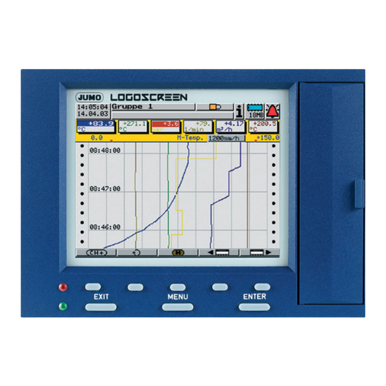
2 Device description 2.1 Displays and controls Power LED (green) is on continuously as soon as power is applied. TFT color display Status LED (red) 320 x 240 pixels, 256 colors is on continuously if an alarm is present. Cover ®... - Page 13 2 Device description Header Status line & Numerical title line Measurement Signal LED Lights up during access to the Setup plug connection CompactFlash for communication with the memory card. setup program CompactFlash slot for data exchange Ejector for the (measurement data, configuration CompactFlash data, user lists) between the memory card...
-
Page 14: Operating Principle And Graphic Elements
2 Device description 2.2 Operating principle and graphic elements Header Fixed functions Variable function with changing symbols Function is activated when the control knob is pressed. The functions of the paperless recorder are selected in the header. The selected function is indicated by a blue background. - Function selection by rotating the control knob (to right or left). - Page 15 2 Device description v Chapter 7 Device manager v Chapter 6 Memory manager v Chapter 5 Alarm and event lists v Chapter 3 Operator level (Visualization) v See “Group selection” on Page 25. Group selection v Chapter 4 Memory presentation v See “Numerical measurement display”...
- Page 16 2 Device description Numerical The numerical measurement display is available for the presentation modes: measurement - Curves display - History (curve display) and (diagram header) - Digital diagram In the curve presentation, the numerical display can be switched on and off. This on and off switching also applies to the history representation.
- Page 17 2 Device description Visualization window (diagram) Symbols for data acquisition: Comment has been entered Event occurred Alarm is no longer present Alarm has been signaled In the visualization window, the measurements are shown in graphical form. Alarms are indicated by a red or orange color for the curve (can be configured in the setup program).
-
Page 18: Operating Example
2 Device description 2.3 Operating example Start The normal display is active. Operation h Select the operator level by rotating the control knob. h Activate the operator level by pressing the control knob. - Page 19 2 Device description h Select bar graph display by rotating the control knob. h Activate bar graph display by pressing the control knob. Result The bar graph display is now started.
-
Page 20: Group And Plant Management (Batches)
2 Device description 2.4 Group and plant management (batches) Within the recorder, all analog inputs, binary inputs, counters and integrators, are collected together into groups. A maximum of nine groups is available as a total. Each group can consist of a maximum of 6 analog inputs, 6 binary inputs/outputs, and 4 counters/integrators. - Page 21 2 Device description In order for a batch to be usable, its main group must be active (status = “Display” or “Display, save”) and at least one analog channel in the group must be assigned. Batch for plant Main group The number of plants is configured by the parameter Device manager ! Configuration ! Batches/plants !
- Page 22 2 Device description...
-
Page 23: Operator Level (Visualization)
3 Operator level (visualization) 3.1 Activate operator level The type of visualization (curve presentation, bar graph etc.) is selected at the operator level. Note that the appearance of the operator level can be influenced by the configuration. h Select the operator level by rotating the control knob. h Activate the operator level by pressing the control knob. -
Page 24: Overview Of Header Lines
3 Operator level (visualization) 3.2 Overview of header lines Curve presentation Bar graph presentation Textual presentation Process diagram Digital presentation Report Batches (current) Batches (finished) Counters and integrators Comment entry The comment entry does not have its own header. The current header will remain when this function is activated. -
Page 25: Curve Presentation
3 Operator level (visualization) 3.3 Curve presentation In the curve presentation, the individual signal traces run from top to bottom of the display (vertical presentation). Group step-on Channel step-on Numerical measurement display Memory presentation Group selection Sampling rate and operating mode: Normal operation... -
Page 26: Bar Graph Presentation
3 Operator level (visualization) Channel This function activates the scaling display. Repeated activation steps through step-on the scaling for the channels within the group, and then blanks it out again. Programmable alarm limits Group Unlike “Group selection”, where any group can be selected, this function step-on selects the groups one after another. -
Page 27: Textual Presentation
3 Operator level (visualization) 3.5 Textual presentation In presentation, the analog channels are presented numerically, together with the channel name and the channel description. In addition to the analog channels, the digital inputs can also be visualized at the right-hand edge of the display. -
Page 28: Process Diagram
3 Operator level (visualization) 3.6 Process diagram In the presentation, selected measurement signals and background pictures are shown in a process diagram (one group per process diagram). The preparation and configuration of the diagram can only be carried out by the device manufacturer. -
Page 29: Report
3 Operator level (visualization) 3.8 Report Each one of the reports covers all the analog channels in a group. An individual and configurable report is provided for each group. The current reports are visualized in the presentation. Group step-on Channel step-on Report step-on Group selection MAX value... -
Page 30: Batches/Plants
3 Operator level (visualization) 3.9 Batches/plants When recording batch processes, a distinction is made between the plant and the batch. The instrument can combine and record the data from up to 3 plants as a batch (batch protocol). The number of batches for a plant is not limited. The instrument distinguishes between “current batch”... - Page 31 3 Operator level (visualization) Edit batch This function can be used to edit the batch text fields that are available (configured for this purpose). When the function has been called up, the first editable field in the screen will be activated. h Press the control knob to start editing.
-
Page 32: Completed Batches
3 Operator level (visualization) 3.9.2 Completed batches Change batch/plant Analyze batch Analyze Completed batches can be analyzed in three different ways: batch - batch data (graphical presentation) - report (numerical presentation) - attachments (e.g. recipes). h Rotate the control knob to select a type of presentation, then press the knob to activate this type. -
Page 33: Batch Control Through Barcode Reader
3 Operator level (visualization) 3.9.3 Batch control through barcode reader If a barcode reader is connected to the interface “RS232 for barcode reader” (extra code, connector 2) or “RS232/RS485” (connector 7), then the batch start, batch stop, and input of batch texts in a current batch report, can be controlled by the barcode reader. - Page 34 3 Operator level (visualization) Activate and display (if required) batch report for plant 3: Start/stop If the batch report is configured for start/stop via barcode reader, then it will batch report be started and stopped as follows. Start batch h Scan bar code for “Batch report for Plant 1 — 3”. h Start scan.
- Page 35 3 Operator level (visualization) The first line of the activated batch report that has been configured for text input via bar code will automatically be filled with the text that corresponds to the bar code. If several line have been configured for bar code activation, then they will be processed one after another, from top to bottom.
-
Page 36: Counters And Integrators
3 Operator level (visualization) 3.10 Counters and integrators In this presentation, the current states of the counters and integrators are displayed, as well as the operating hours counter. Up to 9 counters and integrators can be shown in one screen template. The functional characteristics, as counter, integrator or operating hours counter, are defined in the device configuration. -
Page 37: Comment Entry
3 Operator level (visualization) 3.11 Comment entry This function can be used to enter a text (max. length 31 characters) that is entered in the event list when the input is completed. In the curve presentation (in the displayed group), the text entry is marked by a pencil symbol. - Page 38 3 Operator level (visualization)
-
Page 39: Memory Presentation (History)
4 Memory presentation (History) The memory presentation (History) function can be used to display and check data from the internal main memory of the instrument. The size of the memory for memory presentation can be configured. The memory presentation can be activated in the visualization modes “Curve display”... - Page 40 4 Memory presentation (History) Scroll lines Rotating the control knob moves the cursor through the visualization window. The data in the “Numerical measurement display” are updated for every shift. If you move right up to the edge of the window, the measurement curve will automatically be shifted and the required data will be presented.
- Page 41 4 Memory presentation (History) h Select the date and time, and use OK to close the dialog. If the date that you entered is in the History memory, the cursor will move to this position and the data will be shown. Numerical This function decides whether the MAX or MIN values are shown in the measurement...
- Page 42 4 Memory presentation (History)
-
Page 43: Alarm And Event Lists
5 Alarm and event lists The alarm and event lists can be called up in two ways: - a call from one of the visualizations, e.g. curve presentation (Chapter 3.2 “Overview of header lines”) - a call from the memory presentation (Chapter 4 “Memory presentation (History)”). -
Page 44: Call From One Of The Visualization Modes
5 Alarm and event lists 5.1 Call from one of the visualization modes h In the header line, rotate the control knob to select the bell symbol, and press the knob to activate the symbol. h Select the required list. Activate alarm list Complete list of alarms... - Page 45 5 Alarm and event lists h Rotate the control knob to select a list, then press the knob to activate the list. Example In the example you can see a complete event list. h Close the event list by pressing the control knob. Close list The visualization that was active before the list was called up will now be displayed again.
-
Page 46: Call From The Memory Presentation
5 Alarm and event lists 5.2 Call from the memory presentation h In the header line, rotate the control knob to select the bell symbol, and press the knob to activate the symbol. In memory presentation mode, only the event list for the active group will be shown. -
Page 47: Memory Manager
6 Memory manager The symbol for the memory manager (menu: Memory manager) can be shown in different ways. This shows the available memory of the CompactFlash memory card that has been inserted. If no CF card has been inserted, then one of the following symbols will be shown, depending on the type of data read-out that was configured. - Page 48 6 Memory manager Close memory manager Update CF card Back up -> CF card Config data -> CF card CF card -> config data Save all + update CF card CF card -> user list Close memory Close the memory manager and reactivate the previous visualization. manager Update Measurement data that have not yet been saved are written onto the CompactFlash...
- Page 49 6 Memory manager General note The function Update CF card reads out data that have not yet been read out. After read-out, the data will be marked as read in the instrument, but not deleted. The function Backup CF card reads out all the data from the internal memory, including those that had already been read out.
- Page 50 6 Memory manager...
-
Page 51: Device Manager
7 Device manager The functions of the Device manager vary, depending on whether a user is logged in or not. No user logged in “User” logged in “Master” Close device manager logged in Logging in and logging off Device information Device audit trail Configuration Parameterization... - Page 52 7 Device manager Close device Close the device manager and reactivate the previous visualization. manager v Chapter 7.1 “Logging in and logging off” (Page 53) Log-in and log-off Device This function provides you with information on the hardware and software information components of the instrument.
-
Page 53: Logging In And Logging Off
7 Device manager 7.1 Logging in and logging off h Select the Device manager in the header line, by rotating the control knob. h Activate the Device manager by pressing the control knob. h Activate the Security function in Device manager. Log-in Log-off Change password... - Page 54 7 Device manager h Enter the password by rotating and pressing the control knob, and finish the entry with “OK”. You are now logged in to the system.
-
Page 55: Entering Text And Values
8 Entering text and values 8.1 Text entry 8.1.1 Entering characters If a text entry field is selected, and then activated by pressing the control knob, then a text can be entered or altered. The cursor (position marker) is at the end of the current setting. The active key or function that will be performed when the control knob is pressed is shown in blue. - Page 56 8 Entering text and values h Move the cursor onto the required character, and press the control knob. Character entry Another selection window will open. Reject entry Upper case letter Lower case letter h Rotate the control knob to select upper case (capital) or lower case (small) letters, activate/confirm the choice by pressing the control knob.
-
Page 57: Insert Space
8 Entering text and values h Select “°” and press the control knob. Select temperature All the temperature units that can be selected will now be shown. For better unit legibility, the degree sign (°) and the unit (C or F) are separated, and must be individually selected. -
Page 58: Reject Entry
8 Entering text and values 8.1.7 Reject entry h Select the “Cancel” button ( ) and press the control knob. Character entry will now be ended. The text that was entered is not accepted, and the dialog window is closed. The previously active setting is retained. 8.2 Entry via selection field If a selection field is selected, and then activated by pressing the control knob, then the text (value) can be entered from a previously defined list. -
Page 59: Entering Values
8 Entering text and values 8.3 Entering values 8.3.1 Whole numbers (integers) There are two possibilities for entering integer numbers: - selection by altering the individual digits of a number, or - selection by incrementing and decrementing. Selection by For this entry, each digit of the number (units, tens, ...) and the sign are altering the selected with the control knob. -
Page 60: Real Numbers (Floating Point)
8 Entering text and values 8.3.2 Real numbers (floating point) To enter real numbers (with a decimal point) for each digit of the number (units, tens, ...) the decimal point position and the sign are selected with the control knob. Sequence - Position the cursor. -
Page 61: Index
9 Index Numerics 1-channel presentation Alarm and event list – Alarm and event lists – Alarm limits Alarm lists Audit trail Average – Bar graph presentation – Batches analyze automatic start change edit manual start Change password Channel description Channel name –... - Page 62 9 Index Displays and controls Documentation, arrangement Electrostatic discharge (ESD) Entering values Event lists Event operation Group Group presentation – Group selection – Group step-on Groups – Header History Initialization phase Instrument documentation in printed form Instrument documentation in the form of PDF files Introduction Keys Logging in and logging off...
- Page 63 9 Index Normal display Normal operation Note signs – Numerical measurement display Operating mode – Operator level Parameterization Password Password management Power LED Presentation modes – Process diagram – Report Report step-on Returning Rights Sampling rate Screen saver Screen texts Scroll Search Service...
- Page 64 9 Index Typographical conventions User logged in User list Users logged off standard password standard user Visualization Visualization window Warning signs Warranty Writing configuration data to CF card / reading from CF card Zoom...
- Page 68 JUMO GmbH & Co. KG JUMO Instrument Co. Ltd. JUMO Process Control, Inc. Street address: JUMO House 8 Technology Boulevard Moltkestraße 13 - 31 Temple Bank, Riverway Canastota, NY 13032, USA 36039 Fulda, Germany Harlow, Essex CM20 2TT, UK Phone:...
Need help?
Do you have a question about the LOGOSCREEN and is the answer not in the manual?
Questions and answers