Advertisement
Table of Contents
- 1 Safety Hints
- 2 Assembly Pack Check List
- 3 STEP 3 Handle Bar Assembly
- 4 STEP 4 Connecting Arm Assembly
- 5 Key Functions
- 6 Workout Selection
- 7 Workout Parameters
- 8 Program Operation
- 9 Body Fat Program
- 10 TARGET HEART RATE Program
- 11 HEART RATE CONTROL Program
- 12 Enter Key
- 13 User Program
- 14 Parts List
- Download this manual
Advertisement
Table of Contents

Subscribe to Our Youtube Channel
Related Manuals for Xterra XTR0003 CARDIOFIT 2000


Summary of Contents for Xterra XTR0003 CARDIOFIT 2000
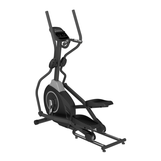
- Page 1 - XTR0003 - CARDIOFIT 2000 ELLIPTICAL OWNER’S MANUAL PLEASE CAREFULLY READ THIS ENTIRE MANUAL BEFORE OPERATING YOUR NEW ELLIPTICAL...
-
Page 2: Safety Hints
Safety Hints WARNING Read all instructions before using this appliance. Do not operate elliptical on deeply padded, plush or shag carpet. Damage ■ to both carpet and elliptical may result. Keep children away from the elliptical. There are obvious pinch points and ■... -
Page 3: Assembly Pack Check List
Assembly Pack Check List STEP 1. #96. 3/8" #112. 3/8" × 23 × 1.5T #104-1 Ø 8.7× 20 × 1.5T Cap Nut Curved Washer Flat Washer (2pcs) (2pcs) (2pcs) #82. M5 × 15m/m #80-1 5/16" × 15m/m Phillips Head Screw Button Head Socket Bolt (4pcs) (2pcs) - Page 4 Assembly Pack Check List STEP 3. #102. Ø 8.7× 20 ×1.5T #74. 5/16" × 15m/m Flat Washer Hex Head Bolt (2pcs) (2pcs) STEP 4. #113. 5/16" × 23 ×1.5T #91. 5/16" × 7T Curved Washer Nyloc Nut (4pcs) (6pcs) #87. Ø3.5 × 12m/m #76.
- Page 5 Assembly Pack Check List TOOLS #116. 12 mm Wrench (1pcs) #115. 13 &14 mm Wrench (1pcs) #118. Combination 5mm Allen Wrench & Phillips Head Screw Driver (1pcs)
- Page 6 Assembly Instructions STEP 1 Front Stabilizer and Connecting Arm Assembly 1. Install the Front Stabilizer(14) on the front stabilizer holding plate at the bottom of the main frame with the transportation wheels facing forward and secure them with 2pcs of 3/8" × 3" Carriage Bolts(77), 2pcs of 3/8" × 23m/m × 1.5T Curved Washers(112) and 2pcs of 3/8"...
- Page 7 STEP 2 Console Mast Assembly 1. Use cable tie to guide the 1150m/m Computer Cable(36) through Console Mast(11) and then pull out of the console holding plate, and Insert the console mast into main frame and secure with 6pcs of 5/16" × 15m/m Button Head Socket Bolts(80), 6pcs of 5/16"...
-
Page 8: Step 3 Handle Bar Assembly
STEP 3 Handle Bar Assembly 1. Install the Lower Handle Bar (L) (9) in the left shaft of Console Mast(11) and the Lower Handle Bar (R) (10) in the right shaft of Console Mast(11), and secure them with 2pcs of 5/16" × 15m/m Hex Head Bolts(74) and 2pcs of Ø8.7 × 20m/m × 1.5T Flat Washers(102) by using 12m/m Wrench(116). -
Page 9: Step 4 Connecting Arm Assembly
STEP 4 Connecting Arm Assembly 1. Connect the Swing Arm (L) (15) to the left Lower Handle Bar and connect the Swing Arm (R) (16) to the right Lower Handle Bar, and secure them with 6pcs of 5/16" ×1-3/4" Hex Head Bolts(76),4pcs of 5/16" × 23m/m × 1.5T Curved Washers(113) and 6pcs of 5/16"... -
Page 10: Key Functions
Console Key Functions 1. Starts & pauses workouts. START/STOP: 2. Starts body fat measurement. 3. Holding key for 3 seconds will reset all function values to zero. DOWN: Decrease value of selected workout parameter: TIME, DISTANCE, etc. During the workout, it will decrease the resistance load. UP : Increases value of selected workout parameter. -
Page 11: Workout Selection
Workout Selection After power-up using UP or DOWN keys to select then pressing ENTER to enter the desired mode. There are 7 basic workout modes: Manual, Pre- programs, Watt Program, Body Fat Program, Target Heart Rate program, Heart Rate Control program and User Program. -
Page 12: Workout Parameters
Functions: SPEED: Displays current training speed. Maximum speed is 99.9 KM/H or MILE/H. RPM: Displays current rotation per minute. TIME: Accumulates the workout time from 00:00 to 99:59. Or users can preset the target time they want. DIST: Accumulates the workout distance from 0.00 up to 999.9 or Miles. -
Page 13: Program Operation
More About Workout Parameters Default Increment/ Field Setting Range Description Value Decrement 1.When display is 0:00, Time Time will count up. 0:00~ 99:00 00:00 ± 1:00 2.When time is 1:00-99:00, It will count down to 0. 1.When display is 0.0, ±1.0 Distance will count up. - Page 14 Pre-programs (P2~P13) Program profile ROLLING VALLEY FAT BURN RAMP STEPS OBSTACLE INTERVALS PLATEAU CLIMBING OFF ROAD HILL PEAK INTERVALS There are 12 program profiles ready for use : : : : R OLLING, VALLEY, FAT BURN, RAMP, STEPS, OBSTACLE, INTERVALS, PLATEAU, CLIMBING, OFF ROAD, HILL and PEAK INTERVALS.All program profiles have 24 levels of resistance.
-
Page 15: Body Fat Program
Setting Parameters for Pre-programs Select one of pre-programs using UP OR DOWN KEY then pressing ENTER KEY. parameter “Time” will flash so value can be adjusted using UP OR DOWN KEY .Press ENTER KEY to save value & move to next parameter to be adjusted. -
Page 16: Target Heart Rate Program
Setting Data for Body Fat Select “BODY FAT Program ” using UP OR DOWN KEY then press ENTER. “Male” will flash so Gender can be adjusted using UP OR DOWN KEY, press ENTER to save gender & move to next data. “... -
Page 17: Heart Rate Control Program
HEART RATE CONTROL Program Program profile There are 4 selection for target pulse: HRC- 55% TARGET H.R= 55% of (220-AGE) HRC - 65% TARGET H.R= 65% of (220-AGE) HRC - 75% TARGET H.R= 75% of (220-AGE) HRC - 85% TARGET H.R= 85% of (220-AGE) Setting Parameters for HEART RATE CONTROL Selecting “One of Heart Rate Control Program .”... - Page 18 Wearing The Chest Strap (Sold Separately) Attach the transmitter to the elastic strap using the locking parts. Adjust the strap as tightly as possible as long as the strap is not too tight to remain comfortable. Position the transmitter with the logo centered in the middle of your torso facing away from your chest (some people must position the transmitter slightly left of center).
-
Page 19: User Program
User Program Program profile 4 User program allow user to set their own program that can be used immediately. Setting Parameters for User Program Selecting user using UP OR DOWN KEY then pressing ENTER KEY. parameter “Time” will flash so value can be adjusted using UP OR DOWN KEY .Press ENTER KEY to save value &... -
Page 20: Parts List
Parts List DESCRIPTION O'TY Main Frame Crank Arm Assembly Pedal Arm(L) Connecting Arm (L) Connecting Arm (R) Lower Handle Bar (L) Lower Handle Bar (R) Console Mast Idler Wheel Assembly Crank Axle Front Stabilizer Swing Arm (L) Swing Arm (R) Rod End Shaft(Blackfast) Axle for Slide Wheel(Blackfast) Aluminum Track... - Page 21 DESCRIPTION O'TY Round End Cap Slide Wheel , Urethane Adjustment Foot Pad WFM-1719-12_Bushing J4FM-1719-09_Bushing Drive Pulley Ø32(1.8T)_Button Head Plug Podwer metallurgy Bushing Rubber Foot Round Cap Pedal Axle Spacer Spacer Bushing Side Case(L) Side Case(R) Crank Arm End Cap Ø56 × Ø19 × 15L_Bushing Ø56 ×...
- Page 22 DESCRIPTION O'TY M5 × P0.8 × 15L_Phillips Head Screw M5 × P0.8 × 10L_Phillips Head Screw M5 × P0.8 × 10L_Phillips Head Screw Ø5 × 19L_Tapping Screw Ø5 × 19L_Tapping Screw 85~1 Ø3.5 × 16L_Sheet Metal Screw Ø3.5 × 12L_Sheet Metal Screw Ø3 ×...
- Page 23 DESCRIPTION O'TY M6 × P1.0 × 15L_Phillips Head Screw Oval End Cap Round Cap C Ring Ø15 × Ø8.5 × 50L_Sleeve Pedal Arm(R)
- Page 25 WARRANTY, SAFETY AND ASSEMBLY INFORMATION XTR0003 –CARDIOFIT 2000 IMPORTANT Please read and retain this manual as it will assist with identification for parts and service. ------------------------------------------------------------------------------------------------------------ BOYLES FITNESS warrants their Cross Trainer to be free from defects in material and workmanship under normal use and service conditions.
- Page 26 BFE Warranty Policy – November 1 2013 When purchased from an authorised BFE distributor the BFE warranty shall guarantee that all framework and components of your product are free from faulty manufacture. All faulty framework and components will be repaired or replaced as set out in this policy.
- Page 27 (c) Power Surges. The computers, control boards and motors are very sensitive to power fluctuations. You must use a surge protector on all items that plug into your mains power otherwise your electronics will not be covered by this warranty. You can purchase these from numerous retailers or you can call us on 02 46 366 680 to get a price.
- Page 28 Additional Warranty If you would like to extend your labour warranty by 1 year ($99), 2 years ($199), 3 years ($299) please contact our office by emailing sales@boylesfitness.com.au (Not available in all areas) Service Department hours: Monday to Friday between 9am and 4pm Service Phone Number: 07 3272 7010 Email: spares@boylesfitness.com.au PLEASE NOTE: that Authorised service technicians do not reside in all areas of this vast country.
Need help?
Do you have a question about the XTR0003 CARDIOFIT 2000 and is the answer not in the manual?
Questions and answers