
Related Manuals for Tenma 72-8155


Summary of Contents for Tenma 72-8155
-
Page 1: Table Of Contents
Model 72-8155: OPERATING MANUAL Table of Contents Title Page Overview Inspection Safety Information Rules For Safe Operation International Electrical Symbols The Meter Structure Functional Buttons Display Symbols Measurement Operation A. Measuring Resistance B. Diode and Continuity Test C. Capacitance Measurement D. - Page 2 Model 72-8155: OPERATING MANUAL...
-
Page 3: Overview
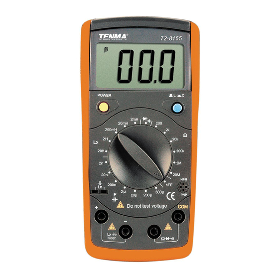
(hereafter referred to as “the Meter”) is a 3 1/2 digits with steady operations, fashionable design and highly reliable hand-held measuring instrument. The Model 72-8155 will measure capacitance, inductance, resistance, transistor hFE and test diodes. It will also test continuity with an audible buzzer. -
Page 4: Inspection
Model 72-8155: OPERATING MANUAL Inspection Open the package case and take out the Meter. Check the following items carefully to see if any items are missing or damaged. Item Description Operating Manual 1 piece Test Clip 1 pair 9V Alkaline Battery (NEDA1604, 6F22... -
Page 5: Rules For Safe Operation
Model 72-8155: OPERATING MANUAL Rules For Safe Operation Warning To avoid possible electric shock or personal injury, and to avoid possible damage to the Meter or to the equipment under test, adhere to the following rules: Before using the Meter inspect the case. Do not use the Meter if it is damaged or the case (or part of the case) is removed. - Page 6 Model 72-8155: OPERATING MANUAL Remove test clips from the Meter and turn the Meter power off before opening the Meter case. When servicing the Meter, use only the same model number or identical electrical specifications replacement parts. The internal circuit of the Meter shall not be altered at will to avoid damage of the Meter and any accident.
-
Page 7: International Electrical Symbols
Model 72-8155: OPERATING MANUAL International Electrical Symbols Ground Double Insulated Low Battery. Continuity Test. Diode. Capacitance Test Inductance Test Fuse. Warning. Refer to the Operating Manual. Conforms to Standards of European Union. -
Page 8: The Meter Structure
Model 72-8155: OPERATING MANUAL The Meter Structure (see figure 1) (figure 1) 1. LCD Display 2. L-C switch 3. Transistor Jack 4. Resistance, Diode and Continuity Input Terminal 5. Capacitance and Inductance Input Terminal 6. Rotary Switch 7. Power. -
Page 9: Functional Buttons
Model 72-8155: OPERATING MANUAL Functional Buttons The following table provides information regarding the functional button operation. Button Description Press the Power down to turn the Meter on. Power Press the Power again to turn the Meter power off. Press L-C down to enter the Capacitance measurement mode. -
Page 10: Display Symbols
Model 72-8155: OPERATING MANUAL Display Symbols (see figure 2) (figure 2) No. Symbol Meaning Data hold is active. The battery is low. Warning: To avoid false readings, which could lead to possible electric shock or personal injury, replace the battery as soon as the battery indicator appears. -
Page 11: Measurement Operation
Model 72-8155: OPERATING MANUAL Measurement Operation Make sure the Low Battery Display is not on, otherwise false readings may be provided. Pay extra attention to the symbol, before measurement, which is located besides the input terminals of the Meter. A. Measuring Resistance... - Page 12 Model 72-8155: OPERATING MANUAL Note When measuring at 20 and 200 range, the test clips can add 0.1 to 0.3 error to resistance. To obtain precise readings in these low-resistance measurement, that is the range 20 and 200 , short circuit the input terminals beforehand and record the reading obtained (called this reading as X).
-
Page 13: Diode And Continuity Test
Model 72-8155: OPERATING MANUAL (figure 4) Warning To avoid damage to the Meter or to the devices under test, disconnect circuit power and discharge all the high-voltage capacitors before measuring diodes and continuity. Testing Diodes Use the diode test to check diodes, transistors, and other semiconductor devices. - Page 14 Model 72-8155: OPERATING MANUAL Note In a circuit, a good diode should still produce a forward voltage drop reading of 500mV to 800mV; however, the reverse voltage drop reading can vary depending on the resistance of other pathways between the probe tips.
-
Page 15: Capacitance Measurement
Model 72-8155: OPERATING MANUAL C. Capacitance Measurement (72-8155 only, see figure 5) (figure 5) Warning To avoid damage to the Meter or to the equipment under test, disconnect circuit power and discharge all high-voltage capacitors before measuring capacitance. The Meter’s capacitance ranges are: 2nF, 20nF, 200nF, 2µF, 20µF, 200µF and 600µF. - Page 16 Model 72-8155: OPERATING MANUAL Note To minimize the effect of capacitance stored in the test clips, the test clips should be as short as possible and use the small value jack when measuring small capacitors. The Meter cannot check the quality of the capacitor.
-
Page 17: Inductance Measurement
Model 72-8155: OPERATING MANUAL D. Inductance Measurement (see figure 6) (figure 6) To test the inductance, please follow the following procedure: Set the rotary switch to Lx measurement mode. If the tested inductance value is unknown, use the maximum measurement position and decrease the range step by step until a satisfactory reading is obtained. -
Page 18: Transistor Hfe Measurement
Model 72-8155: OPERATING MANUAL E. Transistor hFE Measurement (see figure 7) (figure 7) Testing transistors: Set the rotary switch to hFE measurement mode. Check that the transistor is PNP or NPN type. Insert the Insert the transistor to be measured to the corresponding Transistor Jack The Meter displays the tested transistor’s nearest value... -
Page 19: General Specifications
Model 72-8155: OPERATING MANUAL General Specifications Fuse Protection for Inductance and capacitance Input Terminal: 0.315A, 250V, fast type fuse, 5x20 mm. Maximum Display: Display: 1999. Measurement Speed: Updates 2-3 times /second. Polarity: Auto. (Display “-“ when negative) Overloading: Display “1”... -
Page 20: Accuracy Specifications
Model 72-8155: OPERATING MANUAL Accuracy Specifications Accuracy: (a% reading + b digits),guarantee for 1 year. Operating temperature: 23 Relative humidity: < 75%. Temperature coefficient: 0.1 x (specified accuracy) / 1 A. Resistance Test Range Resolution Accuracy (0.8%+3) (0.8%+1) 200k [2%(rdg-12)+5] Remarks: Overload protection: 250V DC or AC rms at all ranges. -
Page 21: Continuity & Diodes
Model 72-8155: OPERATING MANUAL B. Continuity & Diodes Overload Function Range Resolution Protection Diode 250V rms Continuity Remarks: Diode: Open Circuit Voltage around 5.8V, forward current around 1mA. Continuity 10 , beeper sounds continuously. > 10 , beeper may or may not sound. -
Page 22: Inductance Test
Model 72-8155: OPERATING MANUAL D. Inductance Test Tested Frequ- Range Resolution Accuracy ency / Current 0.001mH 20mH 0.01mH (2%+8) 1kHz/150µA 200mH 0.1mH 0.001H (5%+5) 100Hz/15µA 0.01H (5%+15) Remarks: Measure of Inductance: 1H=10 mH = 10 µΗ. Overload Protection: 0.315A, 250V, fast type fuse, 5x20 mm E. -
Page 23: Maintenance
Model 72-8155: OPERATING MANUAL Maintenance This section provides basic maintenance information including battery and fuse replacement instruction. Warning Do not attempt to repair or service your Meter unless you are qualified to do so and have the relevant calibration, performance test, and service information. -
Page 24: Replacing The Battery
Model 72-8155: OPERATING MANUAL B. Replacing the Battery (see figure 8) (figure 8) Warning To avoid false readings, which could lead to possible electric shock or personal injury, replace the battery as soon as the battery indicator “ ” appears. -
Page 25: Replacing The Fuse
Model 72-8155: OPERATING MANUAL C. Replacing the Fuse (see figure 9) (figure 9) Warning To avoid injury due to electrical shock or arc blast, and to avoid damage to the Meter, use specified fuses ONLY in accordance with the following procedure. - Page 26 Model 72-8155: OPERATING MANUAL Copyright 2006 Tenma Test Equipment. All rights reserved. Tenma Test Equipment 405 S. Pioneer Blvd. Springboro,Ohio 45066 www.tenma.com...
Need help?
Do you have a question about the 72-8155 and is the answer not in the manual?
Questions and answers