Table of Contents
Advertisement
Quick Links
Advertisement
Table of Contents

Related Manuals for Tenma 72-8720


Summary of Contents for Tenma 72-8720
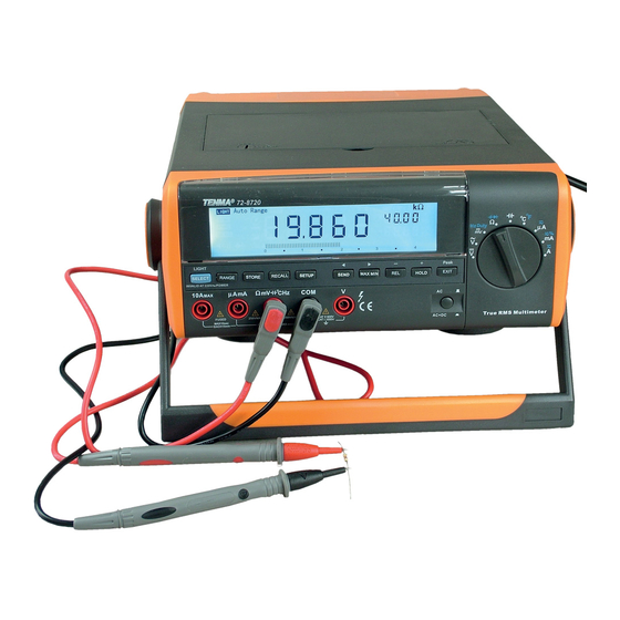
- Page 1 Digital Bench Multimeter Model: 72-8720...
-
Page 2: Important Safety Information
IMPORTANT SAFETY INFORMATION Please read these instructions carefully before use and retain for future reference. • This meter is designed to meet IEC61010-1, 61010-2-032, and 61010-2-033 in Pollution Degree 2, Measurement Category (CAT I 1000V, CAT II 600V, CAT III 300V) and double Insulation. - Page 3 FUNCTIONS Range Selector Rotary Switch Function Blue SELECT Function Positions DC voltage measurement None AC voltage measurement None Hz Duty DC millivolt measurement Frequency measurements Duty Cycle measurement Resistance measurement Diode test Ω Continuity test Capacitance test None ºC ºF Centigrade temp measurement Fahrenheit temp measurement AC or DC current Switch between AC or DC...
-
Page 4: Operating Parameters
Function buttons Operation performed In SETUP each press decrements an option In RECALL each press goes back to previous reading In STORE each press decreases a second on the storing interval. Press EXIT to exit. HOLD freezes the displayed value. Press EXIT to release. HOLD Press to access Peak Hold feature. -
Page 5: Primary Display
Function Primary Display Lower right Upper right Secondary Secondary Display Display Tested DC Voltage value No Display Full range: 4,40,400,1000 Tested frequency Tested AC Voltage value value: 40kHz ~ Full range: 4,40,400,750 250kHz DCmV Tested DCmV value No display Full range: 400 Full range: 400, 4, 40, 400, Ω... - Page 6 • Auto ranging (AUTO in the display) always comes on initially when you select a new function. In auto range, the Meter selects the lowest input range possible, ensuring that the reading appears with the highest available resolution. • Press RANGE to enter MANUAL ranging in the present setting. You can then select the next manual range higher by repeatedly pressing RANGE.
-
Page 7: Hold Peak Hold
Symbol Meaning Indicates lowest setup limit AUTO The meter is set to auto range with range for best resolution selected SEND Data output in progress Backlight feature is on HOLD Data hold mode is active PEAK HOLD Peak hold mode is active Diode test Frequency signal duty cycle. - Page 8 AC Voltage Measurement Warning: To avoid personal injury, or damage to the meter from electric shock, please do not attempt to measure voltages higher than 1000V although readings may be obtained. To measure AC voltage, connect the meter as follows: •...
-
Page 9: Measuring Resistance
DC or AC Current Measurement Warning: Before connecting the meter in series with the circuit under test, be sure power the circuit is off. If the fuse burns out during measurement, the meter may be damaged and there is risk of personal injury to the operator. Use correct terminals, function, and range for the measurement. -
Page 10: Continuity Test
Note: When measuring low resistances, the test leads and internal wiring will add approximately 0.1 ~ 0.2Ω of error. To obtain accurate readings in low-resistance, short- circuit the test lead beforehand and record the reading obtained, call this reading as X. - Page 11 Diode Test Warning: To avoid possible damage to the meter and to the device under test, disconnect circuit power and discharge all high-voltage capacitors before testing diodes. To avoid personal injury, please do not attempt to input voltages higher than 60V DC or 30V AC.
-
Page 12: Frequency Measurement
Note: The Meter displays a fixed value which is the value of the meters own internal circuitry. To ensure accuracy, it is necessary to subtract this value from the displayed value when measuring small capacitors. • Connect the test leads across with the object being measured. The measured value shows on the display. - Page 13 • Place the temperature probe to the object being measured. The measured value shows on the display after few seconds. Note The testing environment must between 18ºC to 28ºC to ensure accuracy especially when measuring low temperature. Different reading may be obtained when testing room environment under short or open circuit situation, then short-circuited reading shall be considered as the correct reading.
- Page 14 Storing and recalling readings • To store a reading: • Press STORE once, STORE and No.xxxx appears to confirm the operation and the upper right secondary display shows the current measurement reading. • Press ► to toggle between clearing the stored readings and start from the first or the last stored reading.
- Page 15 Selection Option Factory default Description Max 4000 Over the upper limits - HIGH Press ► to turn OFF intermittent bleep Press ► to select the digit to edit Max 4000 Over the lower limits - Press ► to turn OFF intermittent bleep Press ►...
-
Page 16: Specification
SPECIFICATION DC Voltage Range Resolution Accuracy Overload Protection 400mV 0.01mV ±(0.025%+5) REL mode 1000V 0.0001V Input impedance 0.001V ±(0.5%+5) At 400mV range : ~ 2.5GΩ 400V 0.01V At all other ranges: ~ 10MΩ 1000V 0.1V ±(0.1%+8) AC Voltage Accuracy 45Hz-1kHz ±(0.4%+30) 0.0001V >1kHz-10kHz... - Page 17 Resistance Range Resolution Accuracy Overload Protection ± (0.3%+40) + test lead open 400Ω 0.01Ω circuit resistance value 4kΩ 0.0001kΩ ±(0.3+40) 40kΩ 0.001kΩ 1000V rms 400kΩ 0.01kΩ ± (0.5%+40) 4mΩ 0.0001MΩ ± (1%+40) 40MΩ 0.001MΩ ± (1.5%+40) Capacitance ± (1%+20) + capacitance value 40nF 0.001nF of open circuit test leads...
-
Page 18: Maintenance
Continuity Test Range Resolution Overload Protection Remarks Open circuit voltage approximate -1.2V. When circuit disconnected with resistance value >50Ω, 0.01Ω 1000V rms buzzer does not sound. When circuit is in good connection with resistance value <10Ω buzzer sounds continuously Diode Test Open circuit voltage approximate 2.8V. - Page 19 Replacing the Battery Warning: To avoid false readings, replace the battery as soon as the battery indicator “ ” appears when using battery to power on the meter. • Press the POWER to turn the meter off and remove all connections from the terminals.
- Page 20 INFORMATION ON WASTE DISPOSAL FOR CONSUMERS OF ELECTRICAL & ELECTRONIC EQUIPMENT These symbols indicate that separate collection of Waste Electrical and Electronic Equipment (WEEE) or waste batteries is required. Do not dispose of these items with general household waste. Separate for the treatment, recovery and recycling of the materials used. Waste batteries can be returned to any waste battery recycling point which are provided by most battery retailers.
Need help?
Do you have a question about the 72-8720 and is the answer not in the manual?
Questions and answers