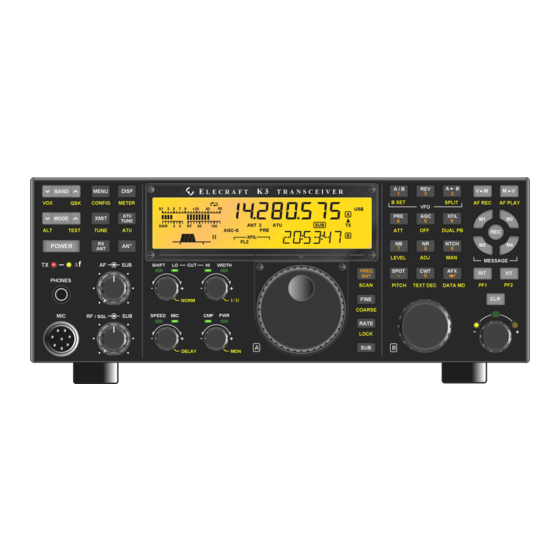
ELECRAFT K3 Installation And Operation Manual
High-performance 160-6 meter transceiver
Hide thumbs
Also See for K3:
- Assembly manual (84 pages) ,
- Owner's manual (82 pages) ,
- Installation and operation manual (55 pages)

Subscribe to Our Youtube Channel
Related Manuals for ELECRAFT K3


Summary of Contents for ELECRAFT K3
- Page 1 LECRAFT 160 – 6 M ERFORMANCE ETER RANSCEIVER K144XV 2-M ETER PTION NSTALLATION AND PERATION Revision E1, January 14, 2016 E740146 Copyright © 2016, Elecraft, Inc. All Rights Reserved...
-
Page 2: Table Of Contents
Parts Included ............................ 7 Installation Procedure ........................... 9 Removing the K3Top Cover ......................9 Preparing the K3 for Installing the K144XV ..................9 Installing the K144XV Module in the K3 ..................13 Enabling the K144XV Module ......................17 Replacing the Top Cover ......................... 18 ... -
Page 3: Introduction
Only a few basic hand tools are needed (see page 6) to perform the installation. A minimal amount of soldering is required to install a power connector on the K3 RF board on some older K3 transceivers. If you have a K3 (not K3 ) see Figure 4 on page 11 for the location of the power connector to see if it is pre-installed. -
Page 4: Customer Service And Support
Elecraft at the time of original order, are not covered by this warranty. If the Elecraft product is being bought indirectly for a third party, the third party's name and address must be provided to Elecraft at time of order to insure warranty coverage. -
Page 5: Assembling And Installing The K144Xv
How ESD Damage Occurs Whenever an object containing a static charge touches a circuit in your K3, current will rush into the circuit until the components reach the same voltage as the source of the static charge. If the voltage or current that passes through a component during that brief period exceeds its normal operating specifications, it may be damaged or destroyed. -
Page 6: Preparing For Installation
If you choose to use a soldering iron to work on your K3 for any reason, be sure your iron has an ESD- safe grounded tip tied to the same common ground used by your mat or wrist strap. -
Page 7: Parts Included
Parts Included The following parts should be included in your kit. Check to ensure you have them all. If any parts are damaged or missing, contact Elecraft for replacements (see Customer Service and Support, page 4). ELECRAFT ILLUSTRATION DESCRIPTION QTY. - Page 8 ELECRAFT ILLUSTRATION DESCRIPTION QTY. PART NO. TMP Cable, 6-Inch (15.2 cm) marked near the connector at each end. (Typically the marking E850389 will be in color. White is shown here for clarity.) E850483 Serial Data Cable Assembly. USB (USB) interface provided unless RS232 specified at the time order is placed.
-
Page 9: Installation Procedure
Preparing the K3 for Installing the K144XV Remove the stiffener bar that runs from side to side across the top of the K3 chassis. This is the bar the three screws across the center of the top cover thread into. The bar is held in place by a single screw at each side... - Page 10 Locate the KXV3A board visible in the lower left corner of the K3 looking in from the open side (see Figure 6 on page 13) and verify the two coaxial TMP connectors are present. If not, your K3 has an older KXV3 board that must be replaced.
- Page 11 Solder the male half of the one –pin connector to the via (copper plated hole through the board) near the front right area of the K3 main RF board just behind the front panel shield as shown in Figure 4. That via may be occupied on some K3 transceivers.
- Page 12 If you have a K3/10 with its blank rear panel, go on to the next step with a square check box. If you have a K3/100, move the circuit breaker and the fans from the existing panel onto the new panel with the ANT 3 hole as follows: Transfer the fans to the new panel.
-
Page 13: Installing The K144Xv Module In The K3
If you have a K3/100, skip this step. If you have a K3/10 with the blank rear panel, replace it as follows: Install the TMP cable with a BNC connector at one end on the blank panel. Remove the nut and lock washer (if on the BNC) and thread the cable through the ANT3 hole in the panel from the side with the ANT3 legend, then replace the lock washer and nut. - Page 14 NOTE: The other connections indicated on the label have no pc board connectors at this time. They are provided for future use. Figure 7. Mounting the K144XV Module in the K3. Skip this step if you are not installing the K144XV Reference Oscillator Phase Lock option at this time.
- Page 15 Figure 8. Installing the K144XV Module Top Cover. If you are installing the K144XV in a K3, connect the 14" (36 cm) power cable between the 3-pin connector on the K144XV module and the 1-pin connector as shown in Figure 9. If you are installing the K144XV in a K3 , use the 5"...
- Page 16 Figure 10. Attaching the Power Cable in a K3 Transceiver. Replace the chassis stiffener using the screws you removed earlier. If your original stiffener lacks the cutout required for the K144XV as shown in Figure 11, use the stiffener supplied with your K144XV kit.
-
Page 17: Enabling The K144Xv Module
In the CONFIG menu, set the parameters shown below. Note: This table assumes you’re using transverter band 1 for the K144XV. (XV1). If you already have one or more external transverters connected to the K3, you can select a different band for the K144XV. For example, if you wish to use band XV2, tap ‘2’ on the numeric keypad before setting up parameters. -
Page 18: Replacing The Top Cover
Figure 12. Connecting the Speaker Cable. Position the top cover on the K3. Note that the tab on the back center goes under the rear lip of the K3 rear panel. Secure the top cover with the nine 4-40 3/16” (4.8 mm) black flat head screws you removed earlier (see Figure 1 on page 9 for the screw locations). -
Page 19: Using The K144Xv
28-MHz drive power is measured and displayed in mW and dBm, just as when using an external transverter. The K3 bar graph shows the drive power in tenths of a mW, so 1 on the bar graph indicates 0.1 mW drive and 10 on the bar graph indicates 1.0 mW drive. -
Page 20: Frequency Calibration
144 to 146 MHz and the other is active from 146 to 148 MHz. Both oscillators must be calibrated to provide an accurate frequency display across the band. The calibration is done by entering a frequency offset in the K3 configuration menu (this was done at the factory if you purchased your K3 with the K144XV already installed). -
Page 21: Status Light
The LED status light on the K144XV module provides operational and diagnostic information. If you suspect a problem with the unit, remove the K3 top cover to see the LED. (There is no need to do this during normal operation.) The LED provides the following indications: Passed Power On self test. -
Page 22: Installing New Firmware
Utility program. When the download is complete, turn the K3 off, wait at least 10 seconds, then turn it on again while watching the STATUS LED. Verify that the STATUS LED flashes once or twice and then turns off, indicating normal operation. -
Page 23: Serial Port Control
1 mA. The jumper is P8 on the K144XV pc board. To access the jumper, remove the K3 top cover (see Figure 1on page 9), then remove the K144XV top cover (see Figure 8on page15). Place the shorting block over both pins of P8.
Need help?
Do you have a question about the K3 and is the answer not in the manual?
Questions and answers