ELECRAFT K3 Owner's Manual
High-performance
160 – 6 meter transceiver
Hide thumbs
Also See for K3:
- Assembly manual (84 pages) ,
- Installation and operation manual (55 pages) ,
- Installation instructions manual (17 pages)

Subscribe to Our Youtube Channel
Related Manuals for ELECRAFT K3


Summary of Contents for ELECRAFT K3
- Page 1 LECRAFT ERFORMANCE 160 – 6 M ETER RANSCEIVER ’ WNER ANUAL Revision D6, December 18, 2009 Copyright © 2009, Elecraft, Inc. All Rights Reserved...
-
Page 2: Table Of Contents
Main and Sub Receiver Antenna Routing..41 Introduction............ 7 Basic K3 (no KAT3 or KXV3)......41 K3 Features ............7 K3 with KXV3 RF I/O Module ......41 Specifications ............8 K3 with KAT3 ATU ........... 42 Customer Service and Support ......10 K3 with KAT3 and KXV3........ -
Page 3: A Note To K3 Owners
And it’s the only rig in its class that you can build yourself. Above all, we want the K3 to be ready for any operating situation you encounter, and be more enjoyable to use than any transceiver you’ve ever owned. -
Page 4: Quick-Start Guide
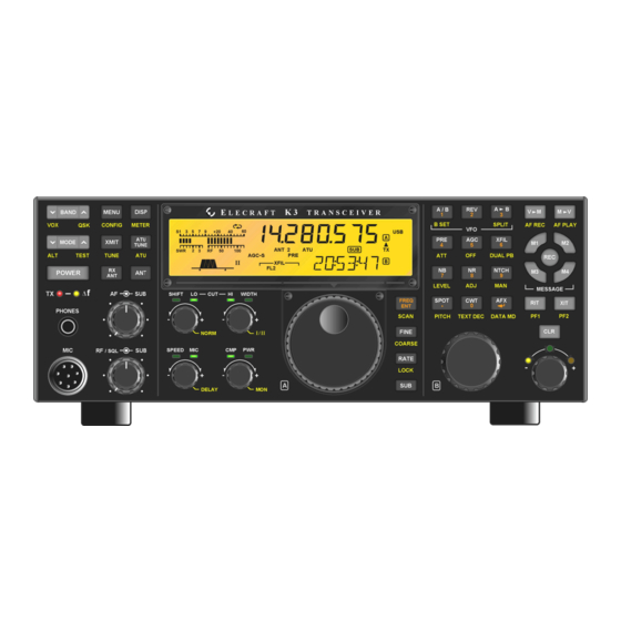
Quick-Start Guide To get started using your K3 right away, please read this page and the two that follow, trying each of the controls. The text uses braces to refer to numbered elements in the front- and rear-panel illustrations below. For example, {1} refers to , the mic jack. - Page 5 Connect a power supply to the DC input jack {26} (see Specifications, pg. 8). • Connections On the K3/100, a circuit breaker is provided on the fan panel for the 100-W stage {38}. • You can power an accessory device from the switched DC output jack {39} (0.5 A max).
- Page 6 The ALARM function (MAIN:ALARM menu entry) can be used to remind you about a • contest, net, or QSO schedule, and can even turn the K3 on at alarm time (pg. 36). The KIO3 module provides a rich set of AF {33} and digital {32} I/O (pg. 17).
-
Page 7: Introduction
• Configuration (pg. 46). manual fine-tuning display (pg. 30) K3 Features User Interface The K3 offers a number of advanced features that Dual VFOs with independent modes, • simplify operation and enhance versatility. These bands, and filter settings (pg. 14) are listed below. -
Page 8: Specifications
Battery: 3 V coin cell (see pg. 48 for replacement instructions). Supply Voltage 13.8 V nominal (11 V min, 15 V max). 17-22 A typical in TX for K3/100, 3-4 A /Current typical in TX for K3/10. 0.9A typical RX (less sub receiver). When using reduced supply voltage (<... - Page 9 K3/100: 0.1 W –100 W typ. Suggested max from 51-52 MHz, 85 W; 52-54, 70 W. K3/10 (or K3/100 with PA bypassed): 0.1 W –12 W, HF-10 m; 8 W max on 6 m. XVTR OUT (KXV3 option): -10 to +1.8 dBm. K144XV: ~10 W, 144-148 MHz.
-
Page 10: Customer Service And Support
Elecraft products transferred by the purchaser to a third party, either by sale, gift, or other method, who is not disclosed to Elecraft at the time of original order, are not covered by this warranty. If the Elecraft product is being bought indirectly for a third party, the third party’s name and address must be provided at time of order to ensure... -
Page 11: Front Panel
Front Panel This reference section describes all front panel controls, the liquid crystal display (LCD), LEDs, and connectors. Operating instructions are covered in later sections. Control Groups Primary Controls (pg 13): These controls Keypad (pg. 15): This group of switches is provide basic transceiver setup, including power numbered for use during memory store/recall and on/off, band, operating mode, AF and RF gain and... -
Page 12: Display (Lcd)
Display (LCD) Multi-character displays: The 7-segment display VFO Icons: The icon indicates which VFO is (upper) shows the VFO A frequency. The 13- selected for transmit. In TX TEST mode, or when segment display (lower) shows VFO B or text. TX is inhibited externally, flashes (see T E S T... -
Page 13: Leds
MAIN:MIC SEL menu entry. Turns the K3 on or off. Note: To ensure P O W E R correct save of operating parameters, turn the Bias must be turned on for electret mics (e.g. -
Page 14: Multi-Function Controls
Transmit Controls Dual-Concentric Potentiometers — AF gain controls for main The primary functions of the transmit controls are: receiver (inner, or smaller knob) and sub receiver Keyer speed in WPM, 8-50 S P E E D (outer ring, or larger knob). Mic gain M I C —... -
Page 15: Keypad
Receiver Control & Misc. (Lower Rows) To jump to any frequency within the tuning range Receiver control functions normally apply to of the K3, tap , then enter 1 to 3 MHz VFO A/main receiver. If is in effect, they... -
Page 16: Memory Controls
When you reach the voice messages during QSOs. CW messages can be desired memory number, tap again to store, viewed and edited using K3 Utility, if desired. or tap to cancel the operation. For details on CW message record/play, see pg. 30. -
Page 17: Rear Panel
+200VDC important for safety and to minimize local RFI. @ 5A. KPA3: This option panel is blank in the K3/10 REF IN (SMA): Input for future external reference. except for ANT3 (see above). In the K3/100, the blank panel is replaced with the fan panel shown, which includes a circuit breaker. -
Page 18: Kio3 Module
ACC connector pinouts are listed below. in/out for use with sound cards, speaker outputs, and auxiliary headphone and mic jacks. ACC is not a VGA video connector. The K3 does not provide a video output. RS232 The RS232 port can operate at up to 38,400 baud. A... - Page 19 5 V on these lines, typically 2.2-10K. Transverter Control In tables below, 0 = 0 VDC, and 1 = 5 VDC. Normally, when the K3 is turned on, a 5-VDC logic With CONFIG:KIO3 set to , the BAND0-3 N O R signal appears on ACC pin 7 (K3 ON).
- Page 20 PTT signal, if used, must be routed to either the PTT IN jack or the PTT line on the ACC connector K3’s LINE OUT level, and can also worsen noise pickup. If your laptop has only a mic input, you (pg.
-
Page 21: Basic Operation
Programmable switches can also be used to order. In the few exceptions to this, adjacent entries automate often-used sequences, or macros, such as are still closely related. “SPLIT, A>B, move VFO B up 5.” Refer to the K3 Programmer’s Reference for detailed examples. - Page 22 Band and Mode Selection Using the VFOs Tap either end of to select the desired ham VFO A is both the main receive and transmit B A N D band (160 through 6 meters). You can use direct frequency, except during SPLIT, in which case frequency entry (pg.
-
Page 23: Receiver Setup
SHIFT selects the upper or lower sideband. You can install as many as five crystal roofing filters in the K3’s main receiver, and another five in Each passband control has an integral switch. These the sub receiver. For diversity receive, matched switches are used as follows: main/sub receiver crystal filters should be used (pg. - Page 24 Hz in CW and DATA modes, 2.7 or 2.8 kHz in SSB modes, and 3.0 kHz for AM For bandwidth settings of 100 Hz or lower, the K3’s Whenever you normalize the filter passband, DSP normally uses a type of filter that minimizes two small "wings"...
-
Page 25: Reducing Interference And Noise
The DSP noise blanker is in the 2 I.F., where it can’t be activated by signals outside the crystal The K3 provides several ways to cut interference, filter passband. It can be used with high-duty-cycle including DSP noise reduction, manual and auto and complex-waveform noise generated by notch, and noise blanking. -
Page 26: Transmitter Setup
If you have a KXV3 installed, you can use Multifunction Transmit Controls milliwatt-level power output. This is intended for use with transverters, but it can also allow the K3 to There are two multifunction transmit controls. Their act as a very stable, very low-noise signal generator. - Page 27 The goal is desired. See the CONFIG:KPA3 menu entry. to have no amplifier ALC action during normal operation. If you see an ALC indication at the K3 or the amplifier, reduce the K3’s power output.
-
Page 28: Voice Modes (Ssb, Am, Fm)
Key the rig again and verify that you have about the right power output level. The K3’s voice monitor allows you to hear the way your voice will sound at your selected mic gain, You can LOCK the MIC, CMP, and PWR compression, and TX EQ settings ( , pg. - Page 29 D E L A Y See CONFIG:TX GATE for details. MAIN:VOX GN (VOX gain) should be set such that the K3 transmits when you speak at a normal AM Operation level, but not in response to incidental noise. Start with low settings (5-10).
-
Page 30: Cw Mode
R E C Q SK then . The remaining buffer space will be K3 returns to receive mode after a time delay you displayed as you send. Tap again to stop. set using . This is a compromise between... -
Page 31: Data Modes
You don’t need a computer to get started with data transmit modes, including PSK31, MFSK, modes on the K3: it can decode and display RTTY AFSK, etc. The VFO displays the suppressed- and PSK31 on its LCD (pg. 33). You can transmit... - Page 32 If the FSK D independently for each of these modes. modem operates from 12 V (0.5 A or less), it can be powered from the K3’s 12 VDC output. FSK Transmit Polarity Set up the modem (if applicable). Settings may •...
-
Page 33: Advanced Operating Features
Decoded text is displayed on VFO B. In data to DATA. Then hold M O D E D A T A M D • modes, you can use the K3’s internal keyer to and select either , or A FS K A FSK D PSK D transmit PSK31 and RTTY signals (pg. -
Page 34: Cw-To-Data
(especially important for between left and right bars. (Also see DTF, pg. 32, PSK D and CONFIG:TTY LTR.) Whenever you pause, the K3 will remain in a • data idle state for about 4 seconds before Manual SPOT dropping. -
Page 35: Audio Effects (Afx)
If you have stereo headphones or stereo external The K3 provides 8 bands of receive audio speakers, you can take advantage of the K3’s DSP equalization via the MAIN:RX EQ menu entry. RX audio effects. These create an illusion of greater EQ can compensate for the physical acoustics of space, similar to stereo. -
Page 36: Split And Cross-Mode Operation
D I S P and other aspects of ESSB performance are not specified. Use ESSB only after carefully The K3 will turn ON automatically if it was off monitoring your signal. at alarm time. It will be on the last-used band. -
Page 37: Using The Sub Receiver
CONFIG:VFO IND The KRX3 option adds an independent, high- . If it’s set to , you’ll see =MA IN performance sub receiver to the K3. It allows you when you tap during , and the sub B SE T B A N D... - Page 38 CW and antennas. The K3 is one of very few transceivers DATA operators should have at least one narrow that offer this capability. Most offer only a low- filter, e.g.
-
Page 39: Receive Antenna In/Out
• in the transverter’s oscillator. Two offsets are provided for the K144XV (see XVn OFS). If you’re comparing the K3 to a transceiver and using its transmit/receive antenna, be sure to set its XVn ADR specifies a transverter select address;... -
Page 40: Scanning
This is muted. Scanning can be used to monitor any portion included in the K3 primarily for use on 60 meters, 6 of a band, from a 1-2 kHz range where a station or meters, and transverter bands, although it can be net is expected to appear, to an entire band. -
Page 41: Main And Sub Receiver Antenna Routing
Basic K3 (no KAT3 or KXV3) As shown in Figure 1, the basic K3 is supplied with one antenna jack (ANT1, SO239). The signal from ANT 1 is routed through the antenna input module (KANT3) to the main receiver (as well as to the transmitter). The KRX3 sub receiver, if installed, can share the ANT 1 signal via a passive splitter and relay K1. -
Page 42: K3 With Kat3 Atu
The KAT3 internal ATU, which replaces the KANT3 antenna input module, provides a second SO239 antenna jack (ANT 2). As shown in Figure 3, relay K3 routes either ANT 1 or ANT 2 to the main RF path. The antenna not routed to the main path (the non-transmit antenna) can optionally be used as the sub receiver’s AUX RF... -
Page 43: K3 With Kat3 And Kxv3
K3 with KAT3 and KXV3 Figure 4 shows the antenna possibilities with both the KAT3 and KXV3 installed. The main receiver can use ANT 1, 2, or RX ANT IN. The sub receiver can either share the main receiver’s RF source, or use its AUX RF input. -
Page 44: Remote Control Of The K3
If you’re not using such software, or if you’re not two DSPs. With appropriate software, various using a computer at all, you can still set up the K3 extensions to DSP functionality can be made to output “IF;” packets periodically by setting... -
Page 45: Options
KBPF3: General-coverage band-pass filter array determine your firmware revision. The serial that allows the K3 main or sub receiver to cover the number of your transceiver, if needed, can be entire LF and HF range of 0.5 to 30 MHz. (If you obtained using the SER NUM menu entry. -
Page 46: Configuration
, corresponds to the nominal 0 .0 0 filter center frequency of 8215.0 kHz. Most 5- Configuring your K3 involves installing options and pole filters will have an offset, e.g. “-0.91”. crystal filters, then customizing menu settings. (This has no effect on performance; firmware compensates for the offset.) -
Page 47: Option Module Enables
CONFIG menu entry to enable it (see VFO Setup below). Then turn the K3 off for 5 seconds, and back on. This allows the K3 to find and test the Several CONFIG menu entries are provided to module. control VFO behavior:... -
Page 48: Vfo A Knob Friction Adjustment
To set the time, date, and date format, refer to the following CONFIG menu entries: TIME, DATE, and DATE MD. (Note: the CONFIG:BAT MIN menu entry refers to a battery used as the K3’s DC power source, not to the 3-V battery.) -
Page 49: Calibration Procedures
T U N E If a computer is available, you should use the This must be done at 5.0 W, 50 W (K3/100 only), automated version of the below procedure. Run and 1.00 mW (if the KXV3 option is installed). -
Page 50: Reference Oscillator
Milliwatt TX Gain Calibration (KXV3) This applies only if you have the KXV3 option. Method 2 (Zero-Beating): (Use the K3 Utility method if a PC is available.) Select CW mode. Set to about 2.8 Connect a 50-ohm resistor to the XVTR OUT jack. -
Page 51: Front Panel Temperature Sensor
AGC ( A G C - S A G C • Turn the K3 OFF. Allow about 15 minutes for • the radio to cool to room temperature. Bypass the ATU, if installed, by holding A T U •... -
Page 52: Menu Functions
Menu Functions There are two groups of menu functions: MAIN and CONFIG. Tap to access the MAIN menu; hold M E N U to access the CONFIG menu. You can also hold to switch from one menu to the other. Menu C O N F I G C O N F I G entries that you’d like quick access to can be assigned to programmable function switches (pg. -
Page 53: Config Menu
ADC REF parameter is being displayed. (Note: The (-) probe of the DMM should go to the K3’s chassis ground, e.g. at the GROUND lug.) Finally, use VFO A to set the ADC REF menu parameter to what you measured at pin 2. - Page 54 (This refers to a battery 1 1 . 0 used as the K3’s DC power supply, not to the 3-V backup battery for the real-time clock.) If the voltage drops below this level, the operator will be alerted with a message.
- Page 55 O FF DIGOUT1 is per-band, and also per-antenna if the KAT3 ATU is installed. It can be used to turn an Elecraft PR6 preamp on when you switch to 6 meters, control a remote antenna switch, etc. Max. load current ( ) is 15 mA;...
- Page 56 (XVTR IN/OUT), and a buffered I.F. output. The updated KXV3A supports the internal 2-m module (K144XV). If KXV3 is set to , the K3 will use low power (0.10 to 1.50 mW) on all TES T bands, including HF and transverter bands. RF input/output is via the XVTR IN/OUT jacks in this case.
- Page 57 RS232 lines to activate PTT or R TS D TR key the K3. (See pg. 18 for connections.) Example: if the parameter is set to , then the RTS line will activate PTT, and DTS will key the rig. Note: R TS - D TR If a computer or other device asserts RTS or DTR while you’re in this menu...
- Page 58 REF CAL 49380000 Used to calibrate the K3’s reference oscillator. VFO A is used to set the reference oscillator frequency in Hz. Typically it will be 49380.000 +/- 1000 Hz. Refer to page 50 for reference oscillator calibration details.
- Page 59 If set to , enables audible switch feedback tones. (Note: For voice feedback on switch press, you may wish to use our K3 Voice program for the PC.) Tones generated: In general, a low-to-high tone pair is generated when a switch function is turned on, and high-to-low when it is turned off.
- Page 60 (Advanced) When SYNC DT (sync data) is activated in either SSB or DATA SYNC DT Function modes, T/R switching times are reduced to optimize for modes such as AMTOR and PacTOR. The “-S” icon turns on. Do not use SYNC DT for normal SSB/DATA communications.
- Page 61 VFO TO L =MFG B). These tolerances are more stringent than normal. This might be useful for those using the K3 over a wider temperature range. VFO Tuning Noise Reduction (Advanced): Tapping in this menu entry alternates between (default) and .
- Page 62 Specify K3 band to use as the I.F. for transverter band n ( . Tap – XVn IF select the transverter band. I.F. selections include , and MHz. XVn PWR L .01 Sets upper limit on power level for XVTR band n. Tap –...
-
Page 63: Troubleshooting
N EW K 3 U TI L SO FT W A R E R EQ U IR E D • install a new version of the K3’s firmware upgrade program (K3 Utility) in order to load the latest K3 firmware. After installing the new version of K3 Utility, reload all new firmware (MCU, DSP, etc.). - Page 64 , but a mono external speaker SPK R S=1 plug is in use, shorting the right speaker channel to ground. The K3 automatically sets SPKRS to No received signal: Check (1) receiver being squelched (if RF/SQL controls are assigned to squelch via •...
-
Page 65: Parameter Initialization
(or re-do all configuration steps manually; no test equipment is required). If you have a computer available to do configuration save and restore, run the K3 Utility program, then use •... -
Page 66: Module Troubleshooting
(pg. 45) or initializing parameters to factory defaults (see below). A full set of schematics can be found on our web site. Due to the use of fine-pitch ICs in the K3, most signal tracing must be done very carefully using fine-tip probes. Please do not attempt this unless you have experience in troubleshooting surface-mount assemblies;... - Page 67 Reload DSP1 firmware (and DSP2 firmware, if applicable). ERR DSG DSP internal gain error Turn K3 off and back on to clear the error condition. Please report this to Elecraft, along with DSP internal error information. (In the TECH MD menu entry, tap to get main/aux DSP info, respectively.)
- Page 68 RF board. ERR IO3 KIO3 not responding The KIO3 may be defective. Note: The K3 can be operated temporarily without the KIO3 installed. You’ll need to use headphones, and there will be no computer or AF I/O available on the rear panel.
- Page 69 KREF3 and other modules. If this doesn’t help, the problem may be on the KREF3 module or the RF board. Note: The K3 cannot be used without a KREF3 module. ERR TXF Invalid transmit crystal filter bandwidth...
-
Page 70: Theory Of Operation
Low Power Amplifier (LPA) The low-power amplifier module is capable of up to 12 W power output, and in the case of the K3/10, is the final amplifier stage. In the K3/100, it provides drive to the KPA3 module. The LPA has three gain stages, the last two of which use high-power MOSFET transistors to allow coverage up through 6 meters. -
Page 71: Noise Blanker
Noise Blanker There are two noise blanker subsystems in the K3: the KNB3 module, and a DSP-based blanker (see DSP on pg. 73). The KNB3 is a narrow I.F. pulse blanker that plugs into the RF board. Its broad input bandwidth ensures minimum stretching of fast noise pulses, so it’s ideal for suppressing noise from power lines,... -
Page 72: Kat3 (Atu) And Kant3
The Digital IO board plugs into the KIO3 Main board. It includes a DE-9 serial port connector for use with an external PC, and a DE-15 accessory connector for external band decoders (such as the KRC-2), transverters (such as the Elecraft XV-series), and similar devices. It is also the connector to which direct FSK or PSK signaling is applied. -
Page 73: Nd Lo)
72). The Front Panel PCB also includes the microcontroller unit (MCU), which manages the operation of the K3. All inputs, whether from a switch, knob or external PC, are recognized and acted on by the MCU. All control outputs –... -
Page 74: Kref3 (Ref./2 Ksyn3 (Synthesizer)
Because of this, the user should set the K3's power output level such that it peaks at or below the safe level for any external amplifier under all speech conditions. -
Page 75: K3 Block Diagram
K3 Block Diagram... -
Page 76: Appendix A: Crystal Filter Installation
), then lift off the top cover at the front. Unplug the speaker, then set the top cover aside in a safe place. The screws that hold the top cover in place are an important part of the K3’s structural design. Please be sure to re-install all of them afterward. - Page 77 200 Hz can be used for CW and narrow-band data receive. A mix of 5-pole and 8-pole filters can be used. There are two rules regarding where these filters can be installed in the K3 and how they’re used: Rule #1: If you plan to use a particular filter for both transmitting and receiving (main receiver), you’ll need to install it on the RF board.
- Page 78 BANDWIDTH FREQ OFFSET If you’ll be changing RF board filters: Turn the K3 upside down, placing a soft cloth beneath it. Remove the seven black pan head screws retaining the front bottom cover, then lift the cover off. Remove the screws holding any existing filters that you’ll need to move to obtain the order listed above (on...
- Page 79 Crystal Filter Setup and follow all instructions for the sub receiver. Position the top cover on the K3, with its rear tab inserted under the top edge of the rear panel. Then plug the speaker wire into P25 on the KIO3 board at the left rear of the K3.
-
Page 80: Index
Index 12 VDC IN, 17 Compression, 14, 26, 28 12 VDC OUT, 17 CONFIG Menu, 21, 46, 52, 53, 60 1-Hz Tuning, 22 Configuration, 7, 46, 65 6-Meter Preamp (PR6), 45 Connector Groups, 17 Accessory 12 VDC Output, 17 Control Groups, 11 Accessory I/O (ACC), 18 Cross-Mode Operation, 6, 34, 36 AF Balance Control, 37, 59... - Page 81 Intermediate Frequency (I.F.), 23, 71 PF1, PF2, 6, 16, 21, 32 K144XV, 39, 45 PLL voltage, 36, 69 K3 Utility PC Application, 44, 45, 46, 63, 65 Pot Test (SW TEST), 59 KANT3, 41, 42, 67, 70, 72 Power Control Locking, 14, 58...
- Page 82 RIT, 6, 11, 14, 16, 22, 61 TCXO, 8, 32, 45, 50, 55, 73 RIT/XIT Offset, 7, 14, 16, 21, 22, 33, 36, 61 Tech Mode Menu Entries, 60 Roofing Filter, 7, 23, 73 Temperature Sensor, 51, 55, 57, 63 RS232, 18, 31, 44, 54, 57, 58, 63, 72 Terminal Emulator, 44 RTC, 47...
Need help?
Do you have a question about the K3 and is the answer not in the manual?
Questions and answers