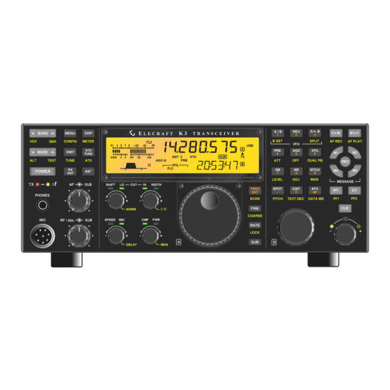
ELECRAFT K3 Installation Instructions Manual
High-performance 160 – 6 meter transceiver
Hide thumbs
Also See for K3:
- Assembly manual (84 pages) ,
- Owner's manual (82 pages) ,
- Installation and operation manual (55 pages)

Related Manuals for ELECRAFT K3


Summary of Contents for ELECRAFT K3
- Page 1 LECRAFT 160 – 6 M ERFORMANCE ETER RANSCEIVER KXV3B I NTERFACE PTION NSTALLATION NSTRUCTIONS Revision C2, July 27, 2015 Copyright © 2015, Elecraft, Inc. All Rights Reserved E740263...
-
Page 2: Table Of Contents
Removing the Bottom Covers and KIO3A/KIO3 Board ..................9 Installing the KXV3B Board ..........................10 Reinstalling the KIO3A/KIO3 Board ........................ 13 Replacing the Top Cover ..........................15 Enabling the KXV3B Module ........................ 16 Elecraft manuals with color images may be downloaded from www.elecraft.com. -
Page 3: Introduction
Repair / Alignment Service (We want to make sure everyone succeeds!) If necessary, you may return your Elecraft product to us for repair or alignment. (Note: We offer unlimited email and phone support to get your kit running, so please try that route first as we can usually help you find the problem quickly.) -
Page 4: Preventing Electrostatic Discharge Damage
Elecraft at the time of original order, are not covered by this warranty. If the Elecraft product is being bought indirectly for a third party, the third party's name and address must be provided to Elecraft at time of order to insure warranty coverage. -
Page 5: Choosing An Anti-Static Mat
#0 and #1 size Phillips screwdrivers. To avoid damaging screws and nuts, a power screwdriver is not recommended. Use the screwdriver that best fits the screw in each step. 2. Wrench to remove jack screw nuts on the K3 back panel. 3/16” nut driver recommended. 3. Small diagonal cutters. -
Page 6: Parts Included
Parts Included The following parts should be included in your kit. Check to ensure you have them all. If any parts are damaged or missing, contact Elecraft for replacements (see Customer Service and Support, page 3). ELECRAFT ILLUSTRATION DESCRIPTION QTY. -
Page 7: Removing The K144Xv 2-Meter Module
KRX3 Sub Receiver Module on page 8. Remove the stiffener bar that runs from side to side across the top of the K3 chassis. This is the bar the three screws across the center of the top cover thread into. The bar is held in place by a single screw at each side and, if the KPA3 100 watt option is installed, by two screws attaching it to the KPA3 shield. -
Page 8: Removing The Krx3A Or Krx3 Sub Receiver Module
Remove the chassis stiffener bar that runs across the top of the K3 chassis and is attached to the side panels. If the KPA3A/KPA3 is installed, the stiffener will be attached to the shield by two screws. These screws may have nuts and lock washers or they may thread into permanently-attached PEM nuts on the stiffener bar. -
Page 9: Removing The Bottom Covers And Kio3A/Kio3 Board
Simply remove the existing KXV3 board and replace it with the KXV3B using the existing TMP cable. Remove the Digital I/O module from the KIO3A or KIO3 Board at the rear of the K3 as shown in Figure 5. Figure 5. Removing the Digital I/O Module. -
Page 10: Installing The Kxv3B Board
RF board (see Figure 7). If soldered to the board, take care not to lose any pieces of wire inside the K3. No more than 1/8” (3mm) of lead length should be left to avoid the possibility of shorting to a nearby circuit. - Page 11 . As you install components and reassemble your K3, be sure all the screws are in place and secure, but do not over tighten them. Failure to tighten all screws may result in poor shielding of sensitive components, resulting in possible noise or birdies in the receiver as well as other difficult-to-trace problems.
- Page 12 Mount the KXV3B rear panel over the BNC connectors using two 4-40 1/2” (13mm) black pan head screws through the corner holes with #4 inside tooth lock washers and 4-40 nuts on the inside as shown in Figure 10. Do not fully tighten the nuts yet. Figure 10.
-
Page 13: Reinstalling The Kio3A/Kio3 Board
If you were directed here to install your KXV3B module as part of the overall kit assembly, installation of the KXV3B module is complete. Return to the K3 Kit Assembly Manual where you left off. Reinstalling the KIO3A/KIO3 Board Replace both bottom covers using the 4-40 black pan head screws you removed earlier. Note that three locations take the 4-40 1/4”... - Page 14 Figure 13. Check KIO3/KIO3A Audio I/O Board Mating. Replace the KIO3A/KIO3 Main Board with the audio I/O daughter board attached in the K3 as shown in Figure 14. The audio I/O board fits just over the KXV3B board assembly and the TMP cable passes through the space between the edge of the KXV3B board and the KIO3 board.
-
Page 15: Replacing The Top Cover
Be sure the cover on battery BT1 on the K3 RF board is in place. The cover is essential to avoid shorting the battery. The outer rim of the battery is the positive terminal, and may come in contact with the grounded bottom of the KRX3 enclosure if the cover is not in place. -
Page 16: Enabling The Kxv3B Module
Figure 17. Connecting Speaker Cable. Position the top cover on the K3. Note that the tab on the back center goes under the rear lip of the K3 rear panel. Secure the top cover with the nine 4-40 3/16” (4.8 mm) black flat head screws you removed earlier. - Page 17 After you have completed the previous steps, set up preamplifier 2 as follows. Preamplifier 2 is an ultra-low noise preamplifier that provides an extra 20 dB of gain on the 12, 10 or 6 meter bands. See your K3 Owner's manual, Preamp and Attenuator Controls, for more information.
Need help?
Do you have a question about the K3 and is the answer not in the manual?
Questions and answers