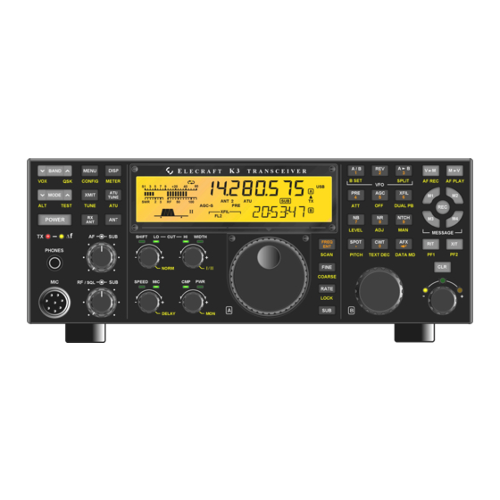
ELECRAFT K3 Quick Start Manual
12vdc out current modification
Hide thumbs
Also See for K3:
- Assembly manual (84 pages) ,
- Owner's manual (82 pages) ,
- Installation and operation manual (55 pages)
Advertisement
Quick Links
Introduction
This modification raises the current available from the 12VDC OUT connector on the K3 from 0.5A to 1.0A. It
involves replacing three components on the K3 RF board: diode D34, choke RFC 48 and resettable fuse F2. This
modification applies only to older K3 transceivers. Later K3 transceivers and all K3
capability from the 12VDC OUT connector.
Parts and Tools Required
You will need a temperature-controlled ESD-Safe soldering station, fine solder, and your normal hand tools such
as needle nose pliers and diagonal cutters. In addition, you will need de-soldering tools such as a solder-sucker or
high-quality de-soldering wick. The action of de-soldering wick is often improved by adding a small amount of
pure rosin-based liquid soldering flux.
A kit containing the required parts is available from Elecraft. Order K312MDKT
QUANTITY
1
1
1
1
Procedure
A grounded wrist strap and ESD dissipating mat are recommended whenever you work inside your K3.
Optionally, touch a bare metal ground frequently while working.
Disconnect power and all cables from your K3.
Whenever you remove screws from a panel, if one screw seems too tight to loosen without
damaging it, first loosen the other screws then try again. Sometimes one screw binds in its
hole when the other screws are tightened.
Remove the screws from the rear section of the K3's bottom cover shown in Figure 1. If either of the two
screws indicated turns but does not unscrew, the spacer it screws into inside is loose. You'll need to remove the
front section of the bottom cover and hold the spacer with long-nose pliers or strong tweezers to remove the
screw. Later you will be instructed to remove the K3 top cover. When you do that locate the screw from above the
pc board that threads into the spacer and tighten it securely.
Elecraft K3
12VDC OUT Current Modification
Revision C, December 22, 2016
Copyright © 2016, Elecraft, Inc. All Rights Reserved
DESCRIPTION
Choke, 10uH 1.28A
Diode
Resettable Fuse, 1.1A
Label, 1.0A SWITCHED, Mylar
Elecraft
•
www.elecraft.com
E740176
ELECRAFT PART
NUMBER
E690303
E560063
E980223
E980226
•
831-763-4211
transceivers provide 1.0A
S
Advertisement

Related Manuals for ELECRAFT K3


Summary of Contents for ELECRAFT K3
- Page 1 Later you will be instructed to remove the K3 top cover. When you do that locate the screw from above the pc board that threads into the spacer and tighten it securely.
- Page 2 Figure 1. Removing Rear Section of Bottom Cover. Replace SMD diode D34 with the new diode supplied with the mod kit (see Figure 2) . The old diode is easily removed without special SMD handling tools by heating and lifting one end of the existing diode at a time using a thin screwdriver or knife blade under the diode.
- Page 3 Figure 3. Removing the Top Cover. Remove the KPA3 fan panel and set it aside (see Figure 4). If you have a K3/10, there will be a blank panel in place of the fan panel that also removes with four screws. Remove the panel and skip the next two steps.
- Page 4 It may be possible to reach the remaining components to be replaced without removing the KPA3 module, but it is a lot easier and you are less likely to accidentally damage the KPA3 if you remove it. There are three screws holding it in place (see Figure 5).
- Page 5 Unplug the KPA3 module from the two multi-pin connectors at the rear edge by placing your thumbs under the back edge of the KPA3 board near the connectors and placing your fingers on the heat sink to gently move the opposite edge of the KPA3 up and down (see Figure 6).
- Page 6 Locate resettable fuse F2 and choke RFC48 (see Figure 7). Remove both RFC48 and F2. Clear the holes of solder. The cleared solder pad locations on the bottom of the board are shown in Figure 8. Be sure the holes are completely clear of solder, especially the holes for F2. The replacement F2 has leads that fit very snugly in the pads, and any solder remaining will prevent inserting the leads.
- Page 7 Install the new resettable fuse F2 and choke RFC48 in the holes and solder. Unlike the diode, they are not polarized. It does not matter which lead goes in which solder pad. However, the new RFC48 is larger than the hole spacing.
- Page 8 Secure the KPA3 module with the three 4-40, 1/4” (6.4mm) zinc pan head screws and lock washers you removed earlier (see Figure 5). Replace the fan panel (see Figure 4). • Be sure the connectors on the circuit breaker fit snugly. If they are loose, squeeze them gently with your needle nose pliers to tighten the fit.
- Page 9 Hold the top cover above the K3 and reconnect the speaker wire (see Figure 12), then replace the top cover and secure it with the nine 4-40 3/16” (4.8 mm) black flat head screws you removed earlier. Figure 12. Reconnecting the Speaker Wire.
Need help?
Do you have a question about the K3 and is the answer not in the manual?
Questions and answers