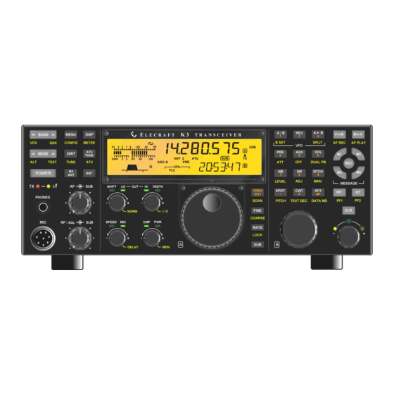
ELECRAFT K3 Installation And Operation Manual
High-performance 160 – 6 meter
transceiver
Hide thumbs
Also See for K3:
- Assembly manual (84 pages) ,
- Owner's manual (82 pages) ,
- Installation and operation manual (23 pages)

Related Manuals for ELECRAFT K3


Summary of Contents for ELECRAFT K3
- Page 1 LECRAFT 160 – 6 M ERFORMANCE ETER RANSCEIVER KRX3A ERFORMANCE ECEIVER NSTALLATION AND PERATION Rev. G1, May 14, 2015 Copyright © 2015, Elecraft, Inc. All Rights Reserved...
-
Page 2: Table Of Contents
Sub Receiver Band Independence ......................... 47 Diversity Receive ............................48 Sub Receiver Crystal Filter Considerations ....................48 SPLIT Mode with the Sub Receiver ......................48 Appendix A: Installing Crystal Filters in the KRX3A Sub Receiver……..………..…………………A1 Elecraft manuals with color images may be downloaded from www.elecraft.com. -
Page 3: Introduction
Only a few basic tools are required to assemble the components and install them in the K3 (see page 6). Figure 1. KRX3A Sub Receiver Installed in K3. -
Page 4: Customer Service And Support
Repair / Alignment Service (We want to make sure everyone succeeds!) If necessary, you may return your Elecraft product to us for repair or alignment. (Note: We offer unlimited email and phone support to get your kit running, so please try that route first as we can usually help you find the problem quickly.) -
Page 5: Preventing Electrostatic Discharge Damage
How ESD Damage Occurs Whenever an object containing a static charge touches a circuit in your K3, current will rush into the circuit until the components reach the same voltage as the source of the static charge. If the voltage or current that passes through a component during that brief period exceeds its normal operating specifications, it may be damaged or destroyed. -
Page 6: Preparing For Installation
If you choose to use a soldering iron to work on your K3 for any reason, be sure your iron has an ESD- safe grounded tip tied to the same common ground used by your mat or wrist strap. -
Page 7: Parts Included
Parts Included The following parts should be included in your kit. Check to ensure you have them all. If any parts are damaged or missing, contact Elecraft for replacements (see page 4). Circuit Boards and Enclosure Note: Some pins on the male connectors may have been removed and some holes in the female connectors may have been plugged. -
Page 8: Krx3A Hardware Bag E850334
ELECRAFT ILLUSTRATION DESCRIPTION QTY. PART NO. KNB3 SUBIN Board E850331 ESD Sensitive. KNB3 SUBOUT Board E850332 KRX3A Enclosure, Top (with tall E100334 standoffs) KRX3A Enclosure, Bottom (with short E100334 standoffs) KRX3A Hardware Bag E850334 ELECRAFT ILLUSTRATION DESCRIPTION QTY. PART NO. -
Page 9: E850344 Tmp-Bnc Cable Bag
ELECRAFT ILLUSTRATION DESCRIPTION QTY. PART NO. Standoff, Hex Male/Female, 7/16” (11mm) E700017 Unthreaded Sleeve Spacer, 7/8” (22 mm) E700161 Screw, Zinc, Pan Head 4-40 1/4” (6.8mm) E700005 Screw, Black, Pan Head, 4-40, 1/2” (13 mm) E700030 Screw, Black, Pan Head, 4-40, 3/16” (4.8 mm) E700015 Screw, Zinc, Pan Head, 4-40, 1-1/2”... -
Page 10: E850249 I.f. Crystal Filter Bag (Or Box)
KFL3A-2.7K Filter Note: This filter is not supplied if you E850249 purchased the optional 8-pole 2.8 kHz filter with your K3 kit. Screw, 4-40, either 1/4” (6.4 mm) Zinc, E700005 or Pan Head or 3/16” (4.8 mm) Black Pan E700015 Head screw. -
Page 11: Installation Procedure
If you have the K144XV 2-meter option installed, slip the speaker wire under the chassis stiffener bar that runs across the top of the K3 along the depression in the top of the K144XV module. Figure 2. Removing K3 Top Cover. -
Page 12: Installing The Auxiliary Dsp Board
Modifying Resistor R91 and DAC Input Circuits on page 20. Stand the K3 on its side feet, remove the six screws shown in Figure 5 and lift the left side panel off. Set the side panel aside in a safe place to avoid scratches. - Page 13 Remove the three screws securing the top of the front panel assembly as shown in Figure 7. Figure 7. Removing Front Panel Mounting Screws. Turn the K3 upside down. Place it on a clean, soft surface to avoid scratching the top of the front or rear panels.
- Page 14 CAUTION Before continuing on with the next step, be sure you have removed the three top Front Panel Assembly screws shown in Figure 7. You may bend and damage the front panel or shield assemblies if the screws are not removed! Use a screwdriver in the pry tool openings to press back against the circuit board while pushing the lip on the front panel assembly toward the front as shown in Figure 9.
-
Page 15: For More Information
With the three screws removed, the main DSP board is held on to the front panel board by two multi-pin connectors. Slip your finger tips between the boards and pull the main DSP board away from the front panel board to unplug it. A large, thick spacer washer should be lying on the front panel near the hole for the phones jack (see Figure 12). - Page 16 Mount the three standoffs on the component side of the main DSP board as shown in Figure 14. Be sure that: The standoffs are on the component side of the board as shown. No lock washer is used between the standoff and the board. ...
- Page 17 Locate resistor R3 on the front panel board (the board still mounted on the front panel assembly). If R3 is positioned above the board on its leads as shown in Figure 16, push it over to one side of the outline as shown. Be sure you don’t push it so far its leads might touch the solder pads for other components on the board.
- Page 18 Plug the aux DSP board into the main DSP board by mating P52 and P53 on the aux DSP board (at the narrow end) with J52 and J53 on the main DSP board. When seated, the connectors should be fully engaged with the aux DSP board resting against the standoffs with the holes in the board aligned for the screws (See Figure 18).
- Page 19 If R3 was positioned above the board on its leads, look between the DSP boards and the front panel board to verify that the leads are not touching any terminals on either the aux DSP or front panel boards (see Figure 19). If necessary, unplug the DSP board assembly and adjust the position of R3 to ensure the leads are clear of other solder pads before proceeding.
- Page 20 Hold the front panel in place against the chassis assembly and turn the unit over to look at the two multi- pin connectors on the top of the RF board. See if they are engaging the corresponding connectors on the front panel assembly (see Figure 21).
-
Page 21: Checking And Modifying Resistor R91 And Dac Input Circuits
Digital to Analog Converters (DACs) receive the proper signal levels. Turn the K3 upside down. Place it on a clean, soft surface to avoid scratching the case. If the forward section of the bottom cover is not already off, remove it as shown in Figure 8 on page 13. -
Page 22: Installing The Krx3A Module Supports
Installing the KRX3A Module Supports Install two standoffs on the K3 RF board (the large board filling the bottom of the K3) as shown in Figure 24. One standoff is mounted next to battery BT1 and the other is mounted next to FL1. Be sure to use two lock washers between the standoffs and the board as shown. -
Page 23: Installing The Auxiliary Ksyn3A Synthesizer
Installing the Auxiliary KSYN3A Synthesizer Remove the KSYN3A board from its ESD protective packaging. Inspect the back of the board for long leads, especially those associated with the mini-connector and U8 near the top of the board. Carefully trim these leads flush with the board as shown in Figure 25. - Page 24 KSYN3A synthesizer board. The other ends of the cable s will be connected later. Installing them now is much easier than after the KSYN3A board in mounted in t he K3. Figure 27. Connecting TMP Cables to the KSYN3A Synthesizer.
- Page 25 Install the Auxiliary KSYN3A board on the back of the front panel shield between the KREF3 board and the side panel as shown in Figure 28.The two cables attached to the KSYN3A board will be attached later. Figure 28. Installing the Auxiliary KSYN3A Board.
-
Page 26: Auxiliary Krx3A Antenna Input (Optional)
Normally, the KRX3A sub receiver will share whatever antenna is in use by the K3 main receiver. If you plan to use the KRX3A sub receiver to listen on one band while the main K3 receiver is on another band sharing the same antenna, there are limitations on the combinations of bands you can choose because of the effect of the bandpass filters used by the main K3 receiver. -
Page 27: Installing The Auxiliary Krx3A Antenna Input Via The Rear Panel Bnc Connector
Route the cable across the back of the K3. When the KRX3A module is installed, it will connect to the KRX3A at a point directly in front of the KIO3 board in the left rear side of the K3. If you have the KPA3 100 watt option installed, route the cable between the fans and heat shield and out through the hole in the KPA3 shield as shown in Figure 29. - Page 28 2D fastener to the rear panel near the SO239 antenna connector shown in Figure 31. Do not lose the lock washer inside the K3. It is easier to keep the hardware from falling inside if you set the K3 on its side feet and remove the screw and lock washer holding the KANT3 or KAT3 board first, then set it on its bottom feet and remove the flat head screw from the 2D fastener.
- Page 29 Check the BNC-TMP cable assembly to see if the nut and lock washer are already threaded onto the BNC connector. If so, remove them completely, working carefully to slide them over the ground braid and lug. (Lay the lug attached to the ground braid along the cable to slide the parts over it.) The dense, highly scratch-resistant powder coating on the rear panel may interfere with the fit of the BNC connector through the hole.
- Page 30 Figure 35. Routing TMP Cable to Rear Panel AUX RF Connector with KPA3 Installed. Replace the right side panel on the K3, installing the 4-40 3/16” flat head screws shown in Figure 32 except for screw number 5. It will be replaced later with the stiffener bar.
-
Page 31: Assembling The Krx3A Sub Receiver Module
Replace the 4-40, 3/16” (4.8 mm) black flat head screw that secures the back panel to the 2D fastener as shown in Figure 31. Replace the two 4-40 3/8” (9.6 mm) black flat head screws, lock washers and nuts to secure the heat sinks of U13 and U12 to the side panel as shown in Figure 30. - Page 32 Locate the crystal I.F. filters. Two types of filters are available: standard 5-pole filters and optional 8-pole filters (see Figure 38). One standard 5-pole 2.7 kHz filter is supplied. If you have elected to equip your K3 with the optional 8-pole 2.8 kHz filter, it has been supplied instead of the 2.7 kHz filter. If you have purchased additional filters, they may be installed now as well.
- Page 33 Enter the FREQ OFFSET shown on each filter. The optional 8-pole filters have no offset marked on them. Enter a zero in the FREQ OFFSET column for those filters. On the 5-pole filters the frequency offset may be negative, indicated by a minus sign (single dash) ahead of the number.
- Page 34 Mount the Mixer and KNB3 boards on the main KRX3A board as shown in Figure 39. Be certain the connector on each board is properly aligned and mated with the connector on the main KRX3A board. The boards should be parallel to the KRX3A board. If they are tilted, check to ensure the correct number of washers were installed under the standoffs and that you used the correct standoffs as shown in Figure 37.
- Page 35 Making this adjustment is described under Filter Loss Compensation in your K3 Owner’s manual.
-
Page 36: Installing The Krx3A Sub Receiver Module
If you haven’t removed it already, remove the chassis stiffener bar. The stiffener is shown in Figure 7. The exposed rim of Battery BT1 on the K3 main RF board must be insulated to prevent shorting against the bottom of the KRX3A enclosure. A plastic battery cover is provided. Fold the battery cover as shown in Figure 43. - Page 37 Place the battery cover on BT1 on the K3 RF board as shown in Figure 44. Hint: gently squeeze the narrow ends of the cover to make the sides bow outward to fit over the battery clip more easily. The cover is held in place by friction against the battery holder and will be trapped under the KRX3A enclosure.
- Page 38 Plug the SUBIN interface board into J64A on the K3 RF board as shown in Figure 46. J64A is directly in front of the KIO3 board in the rear left corner of the K3. Be certain the connector on the SUBIN board is aligned with J64A so all pins are engaged.
- Page 39 Plug the SUBOUT interface board in J64B on the K3 RF board as shown in Figure 47. J64B is between the K3 roofing filters and the front panel. Be certain the SUBOUT board is aligned so all pins of P1 are engaged with J64B.
- Page 40 (see Figure 44). The top edge of the battery is the positive terminal, and touching the enclosure during installation will short-circuit the battery. Hold the assembled KRX3A module directly over the K3 and attach the TMP cables to J82 and J85 on the module as shown in Figure 48.
- Page 41 With all the TMP cables attached, lower the KRX3A module into the K3 so that the connectors on the KRX3A mate with the connectors on the SUBIN and SUBOUT interface boards (see Figure 49). The knurled nuts are provided as handles to make holding the assembly easier. You may need to adjust the cables near the SUBOUT board so they don’t interfere with mating the connectors.
- Page 42 Secure the KRX3A module to the two standoffs using 1-1/2” (38 mm) 4-40 pan head screws as shown in Figure 50. The screws will pass through the internal standoffs and circuit board inside the enclosure and screw into the standoffs you mounted on the K3 RF board earlier. Place an inside tooth lock washer under each screw head.
-
Page 43: Final Assembly
Final Assembly Remove the covering over the self-adhesive side of the foam pad and press the adhesive side against the speaker magnetic shield (see Figure 51). The pad will compress between the loudspeaker and the top of the KRX3Aenclosure when the cover is installed. Figure 51. - Page 44 Figure 53. Connecting Speaker Cable. Position the top cover on the K3. Note that the tab on the back center goes under the rear lip of the K3 rear panel. Secure the top cover with the nine 4-40 3/16” (4.8 mm) black flat head screws you removed earlier.
-
Page 45: Removing The Krx3A Module
It is not necessary to remove the Auxiliary DSP or the Auxiliary KSYN3A synthesizer boards to operate the K3 without the sub receiver module in place, however, leave the KRX3A enabled in the MENU even though you will see error messages relating to the missing KRX3A module when you switch POWER on. Tap to clear the error messages. -
Page 46: Operation
After completing the following steps, refer to the K3 Owner’s manual for more details about listening to both main and sub receivers using line out, stereo phones or dual loudspeakers.) -
Page 47: Using The Sub Receiver
Using the Sub Receiver The KRX3A option adds an independent, high- The sub receiver band cannot be set performance sub receiver to the K3. It allows you independently unless is set to CONFIG:VFO IND to monitor a second frequency, using different . -
Page 48: Diversity Receive
This will ensure that both receivers have antennas. The K3 is one of very few transceivers the same characteristics when strong QRM is that offer this capability. Most offer only a low- present. -
Page 49: Appendix A: Installing Crystal Filters In The Krx3A Sub Receiver
Remove the K3 top cover as shown in Figure A-1. As you lift the cover off unplug the speaker wire that connects to the KIO3 board in the left rear corner of the K3. If you have the K144XV 2-meter option installed, slip the speaker wire under the chassis stiffener bar that runs across the top of the K3 along the depression in the top of the K144XV module. - Page 50 Observe ESD precautions when working inside your K3. Wear an ESD wrist strap or frequently touch an unpainted metal ground while working. Remove the chassis stiffener bar that runs across the top of the K3 (see Figure A-2. Removing the Chassis Stiffener Bar.) .
- Page 51 K3 and the KRX3A enclosure. The boards may still be attached to the K3 main board or may be attached to the connectors on the KRX3A RF module. Set them aside in an ESD-safe place.
- Page 52 A-5, leaving space for a wider bandwidth filter to be added in FL1 position and narrower filters to be added to FL3 through FL5 later if desired. More information and examples for planning your filters is included in Appendix A of your K3 Owner’s manual.
- Page 53 (If you do not have a filter information label on your sub receiver, you can obtain one from Elecraft.) Use pencil in case you change your filters later. Note that the filters read right to left on the label, just as they were installed on the pc board and shown on Table 1.
- Page 54 CAUTION 1) Do not use screws longer than 1/4” (6.4 mm) to mount the filters. Longer screws may extend into the optional 8-pole filter and destroy it. We strongly recommend you use a 1/4” screw even when installing the 5-pole filters to reduce the possibility of damaging an 8-pole filter should you change them later.
- Page 55 Lock washers are not used under the knurled nuts. Turn to your KRX3A Installation and Operation manual, and follow the procedures under Installing the KRX3A Sub Receiver Module and Final Assembly to complete the installation and reassembly of your K3. Note that: a) You will not need to assemble the battery cover, but be sure it is in place on the battery as shown.
Need help?
Do you have a question about the K3 and is the answer not in the manual?
Questions and answers