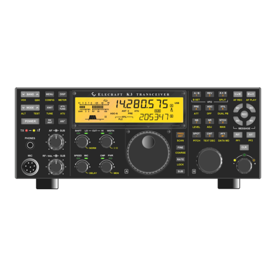
ELECRAFT K3 Installation Instructions Manual
High-performance 160 – 6 meter transceiver/ synthesizer
Hide thumbs
Also See for K3:
- Assembly manual (84 pages) ,
- Owner's manual (82 pages) ,
- Installation and operation manual (55 pages)
Subscribe to Our Youtube Channel
Summary of Contents for ELECRAFT K3
- Page 1 LECRAFT 160 – 6 M ERFORMANCE ETER RANSCEIVER KSYN3A S YNTHESIZER NSTALLATION NSTRUCTIONS Rev A, January 28, 2015 Copyright © 2015, Elecraft, Inc. All Rights Reserved...
-
Page 2: Table Of Contents
Choosing an Anti-Static Mat ..........................6 Preparing for Installation .......................... 7 Tools Required ..............................7 Parts Included ..............................7 Installation Procedure ..........................8 Removing the Top Cover ............................ 8 K144XV Option ..............................8 Replacing the Synthesizer(s) ..........................10 Reassembling the K3 ............................15 ... -
Page 3: Introduction
Checking Synthesizer Types If you are unsure which synthesizer is installed in your K3, open the K3 top cover (see Removing Top Cover on page 8). You don’t need to remove the top cover completely. Only lift it far enough to see the synthesizers (see Figure 1). -
Page 4: Customer Service And Support
Like the original synthesizer, one pin of the multi-pin connector at the bottom has been cut and the corresponding opening in the socket on the K3 RF board has been plugged to assist in properly aligning the connectors when installing the board. - Page 5 Who is covered: This warranty covers the original owner of the Elecraft product as disclosed to Elecraft at the time of order. Elecraft products transferred by the purchaser to a third party, either by sale, gift, or other method, who is not disclosed to Elecraft at the time of original order, are not covered by this warranty.
-
Page 6: Preventing Electrostatic Discharge Damage
Preventing Electrostatic Discharge Damage Sensitive components may be damaged by Electrostatic Discharge (ESD) simply by touching them or a circuit board containing them unless you take specific steps to prevent such damage. Damage may occur with static discharges far too little for you to notice. A damaged component may not fail completely at first. -
Page 7: Preparing For Installation
5. A magnet on a rod (or magnetized screwdriver) is handy to retrieve a dropped part if needed. Parts Included The following parts should be included in your kit. Check to ensure you have them all. If any parts are damaged or missing, contact Elecraft for replacements (see Customer Service and Support on page 4). ELECRAFT ILLUSTRATION DESCRIPTION QTY. -
Page 8: Installation Procedure
K3. See Preventing Electrostatic Discharge on page 6for more information. K144XV Option If your K3 does not have the K144XV 2-meter module option installed go to Replacing the Synthesizer(s) on page 10. Otherwise, move the 2-meter module out of the way as follows:... - Page 9 Remove the stiffener as shown in Figure 4. It will be held in place by a flat head screw through each side panel. If the KPA3 100 watt amplifier option is installed, two screws securing it to the KPA3 shield. Some older K3s may use nuts and lock washers on the screws securing the stiffener to the KPA3 shield instead of PEM nuts.
-
Page 10: Replacing The Synthesizer(S)
Do not lose the lock washers inside the K3. Some builders find it easier to stand the K3 on one side so a dropped lock washer does not fall down onto the main RF board covering the bottom. - Page 11 Remove the replacement KSYN3A synthesizers from their envelopes. You will have two synthesizers only if your K3 is equipped with the KRX3 Subreceiver option. Inspect the back of each board for long leads, especially those associated with the mini-connector and U8 near the top of the board. Carefully trim these leads flush with the board as shown in Figure 9.
- Page 12 Install the main KSYN3A board as shown in Figure 10. Use the interior tooth lock washers you removed earlier with the new screws that came with the synthesizer. Do not replace the lock washers behind the synthesizer board that you removed earlier. The KSYN3A board rests directly against the PEM nuts on the front panel shield.
- Page 13 If your K3 has the KRX3 sub receiver, install the auxiliary synthesizer as follows: 1. First attach two coaxial cables to the pc board before installing it as shown in Figure 11. Connecting these now will simplify connecting them later in the tight space between the sub receiver enclosure and the synthesizer.
- Page 14 Complete installing the coaxial cables connected as shown in Figure 12, depending upon the options you have in your K3. Note that: 1. The cables shown in gray do not change. They are shown in case one becomes disconnected from the KREF3 board while you are working.
-
Page 15: Reassembling The K3
Reassembling the K3 If you have the K144XV 2-meter option installed: 1. Reconnect any coaxial cables you removed (see Figure 13), but do not connect the REF IN cable from the main KSYN3. 2. Replace the cover and attach with the five 4-40 1/4" (6.4 mm) zinc pan head screws and internal tooth lock washers you removed earlier. - Page 16 If you have the KRX3 subreceiver installed, dress the coaxial and power cables as shown in Figure 14. The area on top of the KRX3 enclosure must be clear of all wires and cables as shown for the K3 top to fit properly.
- Page 17 Figure 16. Plugging the Speaker Wire into the KIO3 Board. Position the top cover on the K3. Note that the tab on the back center goes under the rear lip of the K3 rear panel. Secure the top cover with the nine 4-40 3/16” (4.8 mm) black flat head screws you removed earlier (see Figure 3on page 8for the screw locations).


Need help?
Do you have a question about the K3 and is the answer not in the manual?
Questions and answers