Table of Contents
Advertisement
Quick Links
Advertisement
Table of Contents

Subscribe to Our Youtube Channel
Related Manuals for SOYO SY-D6IBA


Summary of Contents for SOYO SY-D6IBA
-
Page 2: About This Guide
It is the policy of Soyo Computer Inc. to respect the valid patent rights of third parties and not to infringe upon or assist others to infringe upon such rights. -
Page 3: Table Of Contents
Table of Contents SY-D6IBA Table of Contents SY-D6IBA MAINBOARD LAYOUT ..........1 CHAPTER 1 INTRODUCTION .............2 KEY FEATURES............2 HANDLING THE MAINBOARD .........5 ELECTROSTATIC DISCHARGE PRECAUTIONS ..5 CHAPTER 2 HARDWARE SETUP ..........6 PREPARATIONS ............6 UNPACKING THE MAINBOARD.......7 INSTALLATION GUIDE..........8 CHAPTER 3 BIOS SETUP UTILITY ...........30 SOYO COMBO SETUP ..........32... -
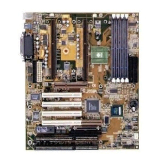
Page 4: Sy-D6Iba Mainboard Layout
Mainboard Layout SY-D6IBA SY-D6IBA MAINBOARD LAYOUT PS/2 KB P S / 2 M o u s e Connector Connector FAN1 FAN2 DIMM 1 CPUFAN CPUFAN DIMM 2 DIMM 3 DIMM 4 USB 2 USB 1 Slot 1 #1 for Slot 1 #2 for... -
Page 5: Chapter 1 Introduction
The SY-D6IBA AGP/PCI mainboard is a high-performance, Single ® or Dual Pentium II processor supported, ATX form-factor system board. SY-D6IBA uses the 82440 BX Chipset technology and ® supports most Pentium II class processors. This mainboard is fully compatible with industry standards and adds many technical enhancements. - Page 6 II 350/400/450/500*/550* MHz with 66MHz FSB: ® Pentium II 233/266/300/333 MHz * The SY-D6IBA mainboard is specially designed to support processors with large frequencies of up to 550MHz. Please note that 500/550MHz processors are not presently available for testing. Ø...
- Page 7 50-pin Fast SCSI Connector onboard (optional) ® RAIDport ™ 60-pin Adaptec RAIDport ™ Slot onboard (optional) SY-D6IBA BACK-PANEL FEATURES 1 x Onboard 26-pin Female Parallel Printer Port Ø ECP/EPP/SPP multi-mode parallel printer port COM1, COM2 2 x Onboard RS-232 Serial Ports Ø...
-
Page 8: Handling The Mainboard
Introduction SY-D6IBA 1-2 HANDLING THE MAINBOARD To avoid damage to your mainboard, follow these simple rules while unpacking: Ø Before handling the mainboard, ground yourself by grasping an unpainted portion of the system's metal chassis. Ø Remove the mainboard from its anti-static packaging. Hold the mainboard by the edges and avoid touching its components. -
Page 9: Chapter 2 Hardware Setup
SY-D6IBA Chapter 2 HARDWARE SETUP Congratulations on your purchase of SY-D6IBA Mainboard. You are about to install and connect your new mainboard. Note: Do not unpack the mainboard from its protective anti-static packaging until you have made the following preparations. -
Page 10: Unpacking The Mainboard
Hardware Setup SY-D6IBA 2-2 UNPACKING THE MAINBOARD When unpacking the mainboard, check for the following items: Ø The SY-D6IBA 82440 BX AGP/PCI Mainboard Ø The Quick Start Guide * Ø The Installation CD-ROM * Ø Two SCSI Driver Installation Diskettes labeled “7800 Family Manager Set V2.10”... -
Page 11: Installation Guide
Slot 1 #1, leaving Slot 1 #2 empty for future expansion to dual CPU. Your SY-D6IBA mainboard comes with two CPU retention set kits. ® The retention set is used to hold each Single or Dual Pentium processor attached to the Slot 1 #1 or Slot1 #2 CPU connectors on the mainboard. - Page 12 Hardware Setup SY-D6IBA 1. Unpack the Retention Set Kit Gather all of the items included in the retention set kit, as shown in the following figure. Supporting Base (x2) Support Clip (x2) Screws (x4) Latches (x4) Retention Clip (x2) 2. Position the Mainboard...
- Page 13 Hardware Setup SY-D6IBA 3. Insert the Screws Install the two pairs of screws used to set the retention clip in the two pairs of holes at both ends of Slot 1#1 and Slot1 #2. Insert the screws from below the mainboard upward, as shown in the figure below.
- Page 14 Hardware Setup SY-D6IBA 5. Install the Retention Clip Set the retention clip centered on Slot 1 and right on top of the two sets of screws along side Slot 1, as shown in the following figure. Then tighten the four screws on the retention clip.
- Page 15 Hardware Setup SY-D6IBA 6. Install the CPU Insert the each CPU into the retention clip in Slot1 #1 and Slot1 #2, and lock the two latches on the sides of the CPUs to secure the ® Pentium II processor in place, as shown in the following figures.
- Page 16 Hardware Setup SY-D6IBA 7. Install the Support Clip Insert the support clip on the supporting base so that the CPU heat sink can seat on top of the supporting base, as shown in the following figure. 8. Insert the Latches...
- Page 17 Hardware Setup SY-D6IBA Step 2. CPU Fan Installation ® Your Pentium II processor kit comes with a cooling fan. Mount the fan on the processor according to the instructions provided by the manufacturer. The fan is a key component that will ensure system stability.
- Page 18 Hardware Setup SY-D6IBA Your board comes with four DIMM sockets, providing support for up to 1GB of main memory using DIMM modules from 8MB to 256MB. For 66MHz front side bus CPUs use 12ns or faster memory; for 100MHz front side bus CPUs use 8ns (100MHz, PC100 compliant) memory.
- Page 19 Hardware Setup SY-D6IBA Step 5. Floppy Drive Installation The system supports 5 possible floppy drive types: 720 KB, 1.2 MB, 1.44 MB, 2.88 MB, and LS-120. In addition, this mainboard supports a 3-mode (720KB/1.2MB/1.44MB) floppy commonly used in Japan. Connect one side of the 34-pin flat cable to the floppy drive and plug the other end to the floppy drive connector on the mainboard.
- Page 20 Hardware Setup SY-D6IBA 2. Reset Plug the Reset push-button cable into the 2-pin Reset header on the mainboard. Pushing the Reset button on the front panel will cause the system to restart the boot-up sequence. 3. Speaker Attach the 4-pin PC speaker cable from the case to the Speaker header on the mainboard.
- Page 21 Hardware Setup SY-D6IBA Step 7. Back Panel Connections All external devices such as the PS/2 keyboard, PS/2 mouse, printer, modem, USB can be plugged directly onto the mainboard back panel. Only after you have fixed and locked the mainboard to the computer case can you start connecting the external peripheral devices.
- Page 22 Hardware Setup SY-D6IBA 2. Parallel Port PRT This parallel port is used to connect the printer or other parallel devices. Plug the parallel device cable into the 26-pin female connector located at the rear panel of the mainboard. 3. PS/2 Keyboard Plug the keyboard jack directly into the 6-pin female PS/2 keyboard connector located at the rear panel of the mainboard.
- Page 23 Hardware Setup SY-D6IBA Please install according to the following pin assignment: Wake-On-LAN JP44 Pin Assignment MP - Wake-up 5VSB 1 2 3 2. Infrared (IR1) Plug the 5-pin infrared device cable to the IR1 header. This will enable the infrared transfer function. This mainboard meets both the ASKIR and HPSIR specifications.
- Page 24 Hardware Setup SY-D6IBA To avoid damage to the system, install according to the following pin assignment: Slot1 #1 CPU Cooling Fan Slot1 #2 CPU Cooling Fan FAN 1 Pin Assignment FAN 2 Pin Assignment SENSOR SENSOR 2. Chassis Cooling Fan (FAN 3) Some chassis also feature a cooling fan.
- Page 25 Hardware Setup SY-D6IBA Step 10. AGP VGA Card Insert the AGP VGA card into the AGP slot. Then connect the monitor information cable to the AGP card back plane external connector. Follow the manufacturer's instructions to perform the AGP VGA drivers installation.
- Page 26 Hardware Setup SY-D6IBA Warning: Follow these precautions to preserve your mainboard from any remnant currents when connecting to ATX power supply: Turn off the power supply and unplug the power cord of the ATX power supply before connecting to ATX PW connector.
- Page 27 Hardware Setup SY-D6IBA Step 13. CMOS Clearing (JP5) After you have turned off your computer, clear the CMOS memory by momentarily shorting pins 2-3 on jumper JP5, for a few seconds. Then restore JP5 to the initial 1-2 jumper setting in order to recover and retain the default settings.
- Page 28 Repeat this operation until you get the following screen. 3. The BIOS Setup screen appears: ROM PCI/ISA BIOS CMOS SETUP UTILITY AWARD SOFTWARE, INC. SOYO COMBO SETUP INTEGRATED PERIPHERALS STANDARD CMOS SETUP SUPERVISOR PASSWORD BIOS FEATURES SETUP USER PASSWORD...
-
Page 29: Cpu Frequency
This mainboard does not use any hardware jumpers to set the CPU frequency. Instead, CPU settings are software configurable with the BIOS [SOYO COMBO SETUP]. The [SOYO COMBO SETUP] menu combines the main parameters that you need to configure, all in one menu, for a quick setup in BIOS. - Page 30 Hardware Setup SY-D6IBA Available [CPU Frequency] settings on your SY-D6IBA Mainboard are detailed in the following table. If you set this field to [Manual], you are then required to fill in the next two consecutive fields: (1) the CPU Host Clock, and (2) the CPU Ratio.
-
Page 31: Troubleshooting At First Start
Select [Save & Exit SETUP] and press <Enter> to save the configuration to the CMOS memory, and continue the boot sequence. Note: SOYO does not guarantee system stability if the user over clocks the system. Any malfunctions due to over-clocking are not covered by the warranty. - Page 32 Hardware Setup SY-D6IBA You are now ready to configure your system with the BIOS Setup program. Please go to Chapter 3: BIOS SETUP...
-
Page 33: Chapter 3 Bios Setup Utility
2. After the diagnostic checks, press the [Del] key to enter the Award BIOS Setup Utility. ROM PCI/ISA BIOS CMOS SETUP UTILITY AWARD SOFTWARE, INC. SOYO COMBO SETUP INTEGRATED PERIPHERALS STANDARD CMOS SETUP SUPERVISOR PASSWORD BIOS FEATURES SETUP USER PASSWORD... -
Page 34: Bios Setup Utility
BIOS Setup Utility SY-D6IBA Hot Keys: Function keys give you access to a group of commands throughout the BIOS utility. Function Command Description Help Gives the list of options available for each item. Color Change the color of the display window. -
Page 35: Soyo Combo Setup
<DEL> key during the system diagnostic checks to enter the Award BIOS Setup program. The CMOS SETUP UTILITY will display on screen. Then, select the [SOYO COMBO SETUP] option from the main menu and press the <Enter> key. - Page 36 BIOS Setup Utility SY-D6IBA 3-1.1 Quick CPU Speed Settings Quick CPU Setting Description Note Speed Settings CPU Speed Manual Select the working 133MHz (66 x 2) frequency of your ® 166MHz (66 x 2.5) Pentium II processor among these preset 200MHz (66 x 3) values.
- Page 37 BIOS Setup Utility SY-D6IBA 3-1.2 L2 Cache Memory Setting Description Note CPU L2 Cache ECC Disabled Default Checking Enabled This option activates the CPU L2 cache ECC checking function. 3-1.3 System Boot Control Settings System Boot Setting Description Note Control Settings...
- Page 38 BIOS Setup Utility SY-D6IBA 3-1.4 Power Management PM Events Setting Description Note POWER ON BUTTON-ONLY Disables the Wake-Up by Default Function Keyboard function. KB Power ON Enables you to wake-up the Password system by entering a password at the keyboard.
- Page 39 BIOS Setup Utility SY-D6IBA 3-1.5 CPU Device Monitoring CPU Device Setting Description Note Monitoring CPU Warning Disabled Default Temperature Enabled Set CPU temperature from 50°C to 70°C. The CPU will slow down when CPU temperature goes beyond the preset value. The CPU...
-
Page 40: Standard Cmos Setup
BIOS Setup Utility SY-D6IBA 3-2 STANDARD CMOS SETUP Select the [STANDARD CMOS SETUP] option from the Main Menu and press [Enter] key. ROM PCI/ISA BIOS STANDARD CMOS SETUP AWARD SOFTWARE, INC. Date (mm:dd:yy) : Mon, Sep 7 1998 Time (hh:mm:ss) -
Page 41: Floppy Drives
BIOS Setup Utility SY-D6IBA 3-2.2 Hard Disks Type & Mode Choose the type and mode for the hard disks that you have already installed. Primary Setting Description Note (Secondary) Master & Slave Type Auto BIOS detects hard disk type Default automatically. - Page 42 BIOS Setup Utility SY-D6IBA 3-2.4 Video Select the video mode: EGA/VGA (Default), CGA 40, CGA 80, MONO (Monochrome). 3-2.5 Halt On When the BIOS detects system errors, this function will stop the system. Select which type of error will cause the system halt: All Errors (Default), No Errors, All But Keyboard, All But Diskette, All But Disk/Key.
-
Page 43: Bios Features Setup
BIOS Setup Utility SY-D6IBA 3-3 BIOS FEATURES SETUP Select the [BIOS FEATURES SETUP] option from the Main Menu and press [Enter] key. ROM PCI/ISA BIOS BIOS FEATURES SETUP AWARD SOFTWARE, INC. Virus Warning : Disabled Video BIOS Shadow : Enabled... - Page 44 BIOS Setup Utility SY-D6IBA 3-3.1 Virus Warning Setting Description Note Virus Warning Disabled Default Enabled Enable this option to protect the boot sectors and partition tables of your hard disk. Any attempt to write to them will the system to halt and display a warning message.
- Page 45 BIOS Setup Utility SY-D6IBA 3-3.4 Typematic Settings Typematic Setting Description Note Settings Typematic Disabled Default Rate Setting Enabled Enables to adjust the keystroke repeat rate. The following [Typematic Rate] and [Typematic Delay] fields are active only if [Typematic Rate Setting] is set to [Enabled]...
- Page 46 BIOS Setup Utility SY-D6IBA 3-3.6 Other Control Options Other Control Setting Description Note Options PCI/VGA Disabled Default Palette Snoop Enabled The color of the monitor may be altered when using an MPEG card. Enable this option to restore the monitor's normal color.
- Page 47 BIOS Setup Utility SY-D6IBA Other Control Options (continued) Other Control Setting Description Note Options Video Disabled BIOS Shadow Enabled Default The BIOS is shadowed in a 16K segment if it is enabled and if it has BIOS present. These 16 segments can be shadowed from ROM to RAM.
-
Page 48: Chipset Features Setup
BIOS Setup Utility SY-D6IBA 3-4 CHIPSET FEATURES SETUP Caution: Change these settings only if you are already familiar with the Chipset. The [CHIPSET FEATURES SETUP] option changes the values of the chipset registers. These registers control the system options in the computer. - Page 49 BIOS Setup Utility SY-D6IBA CHIPSET FEATURES SETUP CHIPSET Setting Description Note FEATURES Auto Disabled Configuration Enabled It is strongly recommended Default to enable this option so that the system automatically sets all chipset feature options on the left panel of the screen (except for cache update &...
- Page 50 BIOS Setup Utility SY-D6IBA CHIPSET FEATURES SETUP (Continued) CHIPSET Setting Description Note FEATURES Passive Release Enabled Use the default setting Default Delayed Enabled Use the default setting Default Transaction AGP Aperture AGP could use the DRAM Default Size 4-256MB as its video RAM. Choose...
-
Page 51: Power Management Setup
BIOS Setup Utility SY-D6IBA 3-5 POWER MANAGEMENT SETUP The [POWER MANAGEMENT SETUP] sets the system's power saving functions. ROM PCI/ISA BIOS POWER MANAGEMENT SETUP AWARD SOFTWARE, INC. Power Management : User Define ** Reload Global Timer Events ** PM Control by APM... - Page 52 BIOS Setup Utility SY-D6IBA 3-5.1 Power Management Controls Power Setting Description Note Management Controls Power User Define Lets you define the HDD and Default Management system power down times. Disable Disables the Green PC Features. Doze Standby Suspend timer timer...
- Page 53 BIOS Setup Utility SY-D6IBA 3-5.2 PM Timers PM Timers Setting Description Note The following [Doze Mode] field may be configured only if [Power Management] is set to [User Define] Doze Mode Disable Default 1Min- When the set time has System clock...
- Page 54 BIOS Setup Utility SY-D6IBA 3-5.3 PM Events PM Events Setting Description Note VGA Active Disabled Default Monitor Enabled Enables the power management timers when a [no activity] event is detected on the monitor. IRQ 8 Break Disabled Default Suspend Enabled Alarm function is active.
-
Page 55: Pnp/Pci Configuration Setup
BIOS Setup Utility SY-D6IBA 3-6 PNP/PCI CONFIGURATION SETUP This option sets the mainboard's PCI Slots. ROM PCI/ISA BIOS PNP/PCI CONFIGURATION AWARD SOFTWARE, INC. PnP OS Installed : No Used MEM base addr : N/A Resources Controlled By : Manual Reset Configuration Data... - Page 56 BIOS Setup Utility SY-D6IBA 3-6.1 PNP/PCI Configuration Controls PNP/PCI Setting Description Note Controls PnP OS Set this field to [Yes] if you Installed are running Windows 95/98, which are PnP compatible. If the OS you are running Default (If there is any...
- Page 57 BIOS Setup Utility SY-D6IBA 3-6.2 PNP/PCI Configuration Setup PNP/PCI Setting Description Note Setup If [Resources Controlled By] is set to [Manual] IRQ-3,4,5,7,9,10, IRQ-# and PCI/ISA PnP Choose IRQ-# and 11,12,14,15 DMA-# DMA-# assigned to DMA-0,1,3,5,6,7 assigned to: PCI/ISA PnP card.
-
Page 58: Load Setup Defaults
This option is recommended if you need to reset the system setup and to retrieve the old values. ROM PCI/ISA BIOS CMOS SETUP UTILITY AWARD SOFTWARE, INC. SOYO COMBO SETUP INTEGRATED PERIPHERALS STANDARD CMOS SETUP SUPERVISOR PASSWORD BIOS FEATURES SETUP USER PASSWORD... -
Page 59: Integrated Peripherals
BIOS Setup Utility SY-D6IBA 3-8 INTEGRATED PERIPHERALS Caution: Change these settings only if you are already familiar with the Chipset. The [INTEGRATED PERIPHERALS] option changes the values of the chipset registers. These registers control the system options in the computer. - Page 60 BIOS Setup Utility SY-D6IBA 3-8.1 IDE Device Controls IDE Controls Setting Description Note IDE HDD Block Mode Disabled Enabled Invokes multi-sector Default transfer instead of one sector per transfer. Not all HDDs support this function. mode 0-4 0 is the slowest speed Ø...
- Page 61 BIOS Setup Utility SY-D6IBA 3-8.3 Keyboard Controls Keyboard Controls Setting Description Note USB Keyboard Disabled Default Support Enabled Use a USB keyboard 3-8.4 Display Controls Display Controls Setting Description Note Init Display First PCI Slot Choose which card – Default AGP Display card or PCI VGA card –...
- Page 62 BIOS Setup Utility SY-D6IBA 3-8.6 Onboard Serial Ports Onboard Serial Setting Description Note Ports Onboard Disabled Ø Serial Port 1 3F8/IRQ4 Choose serial port 1 & Default Ø Serial Port 2 2's I/O address. (port 1) Do not set port 1 & 2 to...
- Page 63 BIOS Setup Utility SY-D6IBA 3-8.7 Onboard Parallel Ports Onboard Parallel Setting Description Note Ports Onboard Parallel 378/IRQ7 Choose the printer I/O Default Port address. 3BC/IRQ7 278/IRQ5 Disable Parallel Port Mode ECP/EPP The mode depends on your external parallel Default device that connects to this port.
-
Page 64: Supervisor Password
BIOS Setup Utility SY-D6IBA 3-9 SUPERVISOR PASSWORD Based on the setting you have made in the [Security Option] of the [BIOS FEATURES SETUP] section, the password prevents access to the system or the setup program by unauthorized users. Follow this procedure to set a new password or disable the password: Choose [BIOS FEATURES SETUP] in the Main Menu and press [Enter]. -
Page 65: User Password
BIOS Setup Utility SY-D6IBA Enter your new password and press [Enter]. The following message appears, prompting to confirm the new password: Confirm Password: Re-enter your password and then press [Enter] to exit to the Main Menu. This diagram outlines the password selection procedure: ↔... -
Page 66: Ide Hdd Auto Detection
BIOS Setup Utility SY-D6IBA 3-11 IDE HDD AUTO DETECTION This Main Menu function automatically detects the hard disk type and configures the STANDARD CMOS SETUP accordingly. ROM PCI/ISA BIOS CMOS SETUP UTILITY AWARD SOFTWARE, INC. HARD DISKS TYPE SIZE CYLS HEAD... -
Page 67: Chapter 4 Drivers Installation
The SOYO CD Start Up Program automatically detects which SOYO mainboard you own and displays the corresponding model name. Step 1. Insert the SOYO CD into the CD-ROM drive The SOYO CD will auto-run, and the SOYO CD Start Up Menu will display as shown below. - Page 68 We recommend that you only install those drivers. To display the list of all drivers software available with SOYO mainboards, click the Display all drivers button the SOYO CD button.
- Page 69 Notice 2: Once you have selected a driver, the system will automatically exit the SOYO CD to begin the driver installation program. When the installation is complete, most drivers require you to restart your system before they can become active.
-
Page 70: Chapter 5 Ultra-Scsi I/O Subsystem
Ultra SCSI I/O Subsystem SY-D6IBA Chapter 5 ULTRA SCSI I/O SUBSYSTEM Note: For details on how to perform the SCSI driver installation, refer to ® the “Adaptec 7800 Family Manager Set User’s Guide” included on the Installation CD-ROM that comes with your mainboard. You may also ®... -
Page 71: Installing Scsi Devices
Ultra SCSI I/O Subsystem SY-D6IBA 5-2 INSTALLING SCSI DEVICES Your mainboard features two internal SCSI connectors onboard, and comes with one 50-pin and one 68-pin flat cables. 5-2.1 50-pin Fast SCSI Connector 50-pin Fast SCSI internal connector Narrow SCSI bus allows data transfer rates of up to 20 Mbytes/sec. -
Page 72: Connecting Internal Scsi Devices
Ultra SCSI I/O Subsystem SY-D6IBA 5-3 CONNECTING INTERNAL SCSI DEVICES If you are connecting several internal SCSI devices (more than 2 CD-ROM drives), make sure you have an internal SCSI cable with enough connectors to accommodate all of your devices. The enclosed SCSI flat cables can serve up to 2 CD-ROM drives. -
Page 73: Adaptec Raidport
Ultra SCSI I/O Subsystem SY-D6IBA 5-4 ADAPTEC RAIDPORT ™ 60-pin Adaptec RAIDport™ slot The onboard Adaptec RAIDport ™ slot is designed to provide embedded SCSI solutions to your mainboard. To use this RAIDport solutions, plug the Adaptec ARO ™-1130 RAIDport ™ card into RAIDport slot on the mainboard.
Need help?
Do you have a question about the SY-D6IBA and is the answer not in the manual?
Questions and answers