CAME Z Series Manual
Hide thumbs
Also See for Z Series:
- Installation manual (80 pages) ,
- Manual (36 pages) ,
- Instructions manual (31 pages)
Advertisement
Quick Links
CANCELLI AUTOMATICI
ITALIANO
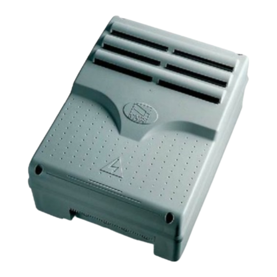
Descrizione quadro
Il quadro elettrico ZC3 è adatto al
comando di una automazione per
portoni industriali scorrevoli della serie
C e F3000, alimentati a 230V con
potenza fino a
600W, frequenza 50÷60 Hz.
Progettato e costruito interamente dalla
CAME S.p.A., risponde alle vigenti
norme UNI 8612. Contenitore in ABS
con grado di protezione IP54, dotato di
presa per il riciclo d'aria e completo di
trasformatore.
Il circuito va alimentato
con tensione di 230V
Z | Z
SERIE
SERIES
SCHEDA COMANDO
CONTROL BOARD
CARTE DE COMMANDE
STEUERPLATINE
TARJETA DE MANDO
240 mm
CARATTERISTICHE GENERALI
/
Z |
SÉRIE
BAUREIHE
120 mm
145 mm
(a.c.) nei morsetti L1- L2 e protetto in
ingresso con due fusibili da 5A,
mentre i dispositivi di comando a
bassa tensione sono protetti con
fusibile da 1A.
La potenza complessiva degli
accessori (24V) non deve superare i
20W.
Il quadro include la funzione di spunto
manovra. Questa funzione si attiva in
fase di inizio apertura e chiusura del
portone.
Z |
Z
SERIE
Documentazione
ZC3
Tecnica
S33
2.2
rev.
09/2001
©
CAME
CANCELLI
AUTOMATICI
319S33
Advertisement

Related Manuals for CAME Z Series


Summary of Contents for CAME Z Series
- Page 1 600W, frequenza 50÷60 Hz. accessori (24V) non deve superare i Progettato e costruito interamente dalla 20W. CAME S.p.A., risponde alle vigenti Il quadro include la funzione di spunto norme UNI 8612. Contenitore in ABS manovra. Questa funzione si attiva in...
-
Page 2: General Characteristics
600W power and 50- gate, with activation of an automatic 60 Hz frequency. closing cycle (2-CX, dip n°8 OFF - 9 Wholly designed and built by CAME ON); S.p.A., it meets UNI 8612 regulations - Total stop (1-2), shutdown of gate in force. - Page 3 until they are completely closed ment of the TCA trimmer and of the po- (including the time required for the sition of Dip 1; it is set at 8 seconds. automatic closure). In case automatic 2) Dip 12 set to OFF: after a partial closure is not enabled, the lamp opening, the time for automatic closing remains lit only during movement (E-...
- Page 4 SCHEDA BASE - MOTHERBOARD - CARTE BASE - GRUNDPLATINE - TARJETA BASE Nota: collegare i fili neri che fuoriescono dalla scheda sui connettori del condensatore. NB: connect the black wires coming out of the board to the condenser’s connectors. T.L. T.C .A.
- Page 5 ENGLISH MAIN COMPONENTES 1 Terminal block for external conections 2 Line fuses, 5A 3 Fuse on accessory power line, 1A 4 24V power-supply signalling LED 5 Trimmer for adjustment operating time 6 Trimmer for adjustment automatic closing 7 Trimmer for adjustment partial opening 8 Signal LED 9 Radio-code save buttons 10 20-Dip function switch (see pag.20)
- Page 6 COLLEGAMENTI ELETTRICI - ELECTRICAL CONNECTIONS - BRANCHEMENTS ÉLECTRIQUES ELEKRISCHE ANSCHLÜSSE - CONEXIONES ELÉCTRICAS L1 L2 U V W E EX 10 11 TS 1 2 3 3P 4 5 7 2 C1CXFCFA F B1B2 Alimentazione 230V (a.c.) 230V (a.c.) power input Alimentation 230V (c.a.) Stromversorgung 230V (Wechselstrom) Alimentación 230V (a.c.)
- Page 7 Lampada spia (24V-3W max.) "portone aperto" (24V-3W max.) "gate-opened" signal lamp Lampe-témoin (24V-3W max.) "portail ouverture" Signallampe (24V-3W max.) "Tor Öffnen" Lámpara indicadora (24V-3W max.) "puerta abierta" Pulsante stop (N.C.) Pushbutton stop (N.C.) Bouton-poussoir arrêt (N.F.) Stop-Taste (Ruhekontakt) Pulsador de stop (N.C.) Pulsante di apertura (N.O.) Pushbutton opens (N.O.) Bouton-poussoir de ouverture (N.O.)
- Page 8 Collegamento finecorsa chiude Connection limit switch closes Connexion fin de course fermeture Anschluß Endschallter Schließen Conexión fin de carrera cierre Collegamento finecorsa apertura Connection limit switch opens Connexion fin de course ouverture Anschluß Endschallter Öffnen Conexión fin de carrera apertura Uscita contatto (N.O.) Portata contatto: 5A - 24V d.c.
- Page 9 ISTRUZIONI MONTAGGIO QUADRO S4340 - ASSEMBLY INSTRUCTIONS S4340 PANEL INSTRUCTIONS MONTAGE ARMOIRE S4340 MONTAGEANWEISUNGEN SCHALTTAFEL S4340 - INSTRUCCIONES MONTAJE CUADRO S4340 Assemblare le cerniere a pressione Assemble the hinges by pressure Assembler les charnières à pression Setzen Sie die Druckscharniere zusammen. Inserire le cerniere nella scatola (sul lato Ensamblar las bisagras a presión destro o sinistro a scelta) e fermarle con le...
- Page 10 TEST FUNZIONAMENTO FOTOCELLULE - PHOTOCELL FUNCTION TEST TEST FONCTIONNEMENT PHOTOCELLULES TEST FÜR DAS FUNKTIONIEREN DER LICHTSCHRANKEN - TEST FUNCIONAMIENTO FOTOCELULAS FIG. 1 FIG. 2 ABB. 1 ABB. 2 FUSIBILE 200mA C NC «DOC» 10 11 TS 1 2 3 3P 4 5 7 «DIR»...
-
Page 11: Dip Switches
SELEZIONI FUNZIONI - SELECTION OF FUNCTIONS - SÉLECTION FONCTIONS FUNKTIONSWAHL - SELECCIÓN DE LAS FUNCIONES DIP-SWITCHES (1-10) T.L. T.C. A. AP .PARZ. FUS . ACCE SSORI 1A 9 1 0 1 3 1 4 1 5 1 6 1 7 1 8 1 9 2 0 QUAD RO COMAN DO FUS . - Page 12 ENGLISH 1 ON Automatic closure activated; (1OFF-deactivated) 2 ON "Open-stop-close-stop" with button (2-7) and radio control (AF board inserted) activated; 2 OFF "Open-close" with button (2-7) and radio control (AF board inserted) activated; 3 ON "Only opening" with radio control (AF board inserted) activated; (3OFF- deactivated) 4 OFF "Operator present"...
- Page 13 DIP-SWITCHES (11-20) T.L. T.C. A. AP .PARZ. FUS . ACCE SSORI 1A 9 1 0 1 3 1 4 1 5 1 6 1 7 1 8 1 9 2 0 QUAD RO COMAN DO FUS . LINEA 5A 13 14 15 16 17 18 19 20 ITALIANO Non utlizzato, tenere il dip in posizione «OFF»...
- Page 14 REGOLAZIONI - ADJUSTMENTS - RÉGLAGES - EINSTELLUNGEN - REGULACIONES ITALIANO REGOLAZIONE TRIMMERS TRIMMERS ADJUSTMENT RÉGLAGE TRIMMERS Trimmer T.L. = Regolazione tempo EINTELLUNG TRIMMERS di lavoro da un minimo di 10 secon- REGULACIÓN TRIMMERS di a un massimo di 150 secondi. T.L.
- Page 15 COLLEGAMENTO PER 2 MOTORI ABBINATI - CONNECTIONS FOR 2 COMBINED MOTORS CONNEXIONS POUR 2 MOTEURS ACCOUPLÉS ANSCHLUSSE FÜR 2 PARALLELGESCHALTETEN MOTOREN - CONEXIÓN PARA 2 MOTORES ACOPLADOS ITALIANO Nel caso di installazione di due motori abbinati, procedere nel seguente modo: 1) Coordinare il senso di marcia dei motoriduttori "A"...
- Page 16 panel; 5) Make the necessary electric con- nections between the terminal boards of Scheda base del motore "A" "A" Motor main board the "A" and "B" panels as in «Fig. A»; Carte de base du moteur "A" N.B. In order to control the automation Basiskarte vom Motor "A"...
- Page 17 «Fig.A» Morsettiera del quadro motore «A» Morsettiera del quadro motore «B» «Abb.A» Terminal board of the "A" motor control panel Terminal board of the "B" motor control panel Plaque à bornes du tableau du moteur «A» Plaque à bornes du tableau du moteur «B» Klemmbrett der Schalttafel vom Motor «A»...
Need help?
Do you have a question about the Z Series and is the answer not in the manual?
Questions and answers