Samsung OfficeServ 7200-S Installation Manual
Hide thumbs
Also See for OfficeServ 7200-S:
- General description manual (104 pages) ,
- User manual (20 pages)
Table of Contents
Advertisement
Quick Links
OfficeServ 7200-S
TECHNICAL MANUAL
T A B L E
INSTALLATION SECTION
PART
DESCRIPTION
1
1.1 SITE REQUIREMENTS .......................................................................................................... 1.1
1.2 GROUNDING CONDITIONS.............................................................................................. 1.2
1.3 POWER CONDITIONS ......................................................................................................... 1.4
1.4 UNPACKING AND INSPECTION ...................................................................................... 1.4
2
2.1 SYSTEM INSTALLATION PROCEDURE .......................................................................... 2.1
2.2 SELECTING INSTALLATION METHOD ........................................................................... 2.1
2.3 INSTALLING IN A RACK ..................................................................................................... 2.1
2.4 INSTALLING ON A WALL .................................................................................................. 2.4
2.5 CONNECTING GROUND WIRES ...................................................................................... 2.8
3
3.1 CABINET CONFIGURATION.............................................................................................. 3.1
3.2 MP20S MODULES ............................................................................................................... 3.3
3.3 INTERFACE BOARDS/CARDS ......................................................................................... 3.10
3.4 DAUGHTERCARD MODULES ......................................................................................... 3.37
3.5 CONNECTING POWER FAIL TRANSFER ...................................................................... 3.43
4
4.1 CONNECTING EXTERNAL BATTERIES ........................................................................... 4.1
5
5.1 BEFORE CONNECTING POWER....................................................................................... 5.1
5.2 PROCEDURE FOR CONNECTING POWER .................................................................... 5.1
5.3 CONNECTING THE OS 7150 EXTERNAL PoE PSU SUPPLEMENTAL POWER
SUPPLY .............................................................................................................................................. 5.2
6
CONNECTING C.O. LINES
6.1 SAFETY PRECAUTIONS ...................................................................................................... 6.1
6.2 CONNECTING C.O. LINES .................................................................................................. 6.2
O F
C O N T E N T S
Home Page
INSTALLATION
PART 1 JANUARY 2011
PAGE
Advertisement
Table of Contents

Related Manuals for Samsung OfficeServ 7200-S


Summary of Contents for Samsung OfficeServ 7200-S
- Page 1 Home Page OfficeServ 7200-S INSTALLATION TECHNICAL MANUAL PART 1 JANUARY 2011 T A B L E C O N T E N T S INSTALLATION SECTION PART DESCRIPTION PAGE PRE-INSTALLATION INFORMATION 1.1 SITE REQUIREMENTS ......................1.1 1.2 GROUNDING CONDITIONS....................1.2 1.3 POWER CONDITIONS ......................
-
Page 2: Table Of Contents
Home Page OfficeServ 7200-S INSTALLATION TECHNICAL MANUAL PART 1 JANUARY 2011 CONNECTING STATIONS AND ADDITIONAL EQUIPMENT 7.1 CONNECTING STATIONS ....................7.1 7.2 CONNECTING ADDITIONAL EQUIPMENT ..............7.27 POWER UP PROCEDURES 8.1 PRE-CHECK ..........................8.1 8.2 STARTING THE SYSTEM ....................8.1 8.3 CHECKING THE FAN ...................... - Page 3 Home Page OfficeServ 7200-S INSTALLATION TECHNICAL MANUAL PART 1 JANUARY 2011 Figure 3.6 Mounting a Modem Card on the MP20S Figure 3.7 Mounting a 4SWM on the MP20S Card Figure 3.8 Real Time Clock Battery (RTC) Figure 3.9 Front View of the MP20S Figure 3.10...
- Page 4 Home Page OfficeServ 7200-S INSTALLATION TECHNICAL MANUAL PART 1 JANUARY 2011 Figure 3.44 CNF24 Progress Bar Figure 3.45 4SWM Figure 3.46 Modem Card Figure 3.47 4TRM Figure 3.48 4DLM Figure 3.49 4SLM Figure 3.50 Power Fail Transfer Connection to 16MWSLI/16SLI2/8SLI/8SLI2 Figure 4.1...
- Page 5 Home Page OfficeServ 7200-S INSTALLATION TECHNICAL MANUAL PART 1 JANUARY 2011 Figure 7.15 Attaching 7B/Single Line to AOM and 7B/Single Line to 64 Button Module Figure 7.16 Attaching the iDCS 64 Button Module to an iDCS Keyset Figure 7.17 Attaching iDCS 14 Button AOM to an iDCS Keyset Figure 7.18...
- Page 6 Rated Output in the Case of Operation with AC Table 5.4 Rated Output in the Case of Operation with DC Table 6.1 OfficeServ 7200-S Line Conditions Table 7.1 Distance Between Stations and the System Table 7.2 Specification for Wireless LAN Connection Table 7.3...
-
Page 7: Site Requirements
• Do not install in close proximity to a fire sprinkler or other sources of water. • A dedicated commercial AC power outlet is required. Do not use extension cords. • Ensure that all wires and cables to and from the OfficeServ 7200-S do not cross fluorescent lights or run in parallel with AC wires. -
Page 8: Grounding Conditions
The OfficeServ 7200-S system requires that a supplementary earth ground be connected to the system. This is the preferred method of grounding the OfficeServ 7200-S. It should be noted that when the third wire ground becomes inferior it many prevent the digital data bus from canceling out noise. - Page 9 S system to drain this energy off. Again, a good earth ground source is required by the OfficeServ 7200-S system. The OfficeServ 7200-S system has two ground reference points. One point is via the green wire in the power cord connected to the AC power outlet. This ground connection is provided to meet local electrical codes when the AC ground is required to be common with the earth ground.
-
Page 10: Unpacking And Inspection
PART 1 MAY 2010 1.3 POWER CONDITIONS The power supply board of the OfficeServ 7200-S system receives AC input power or battery power, and supplies -48V, -5V, +5V, +3.3V, +12V, and -56V to the system cabinet. The rating is as follows: •... -
Page 11: Selecting Installation Method
6) Connect AC 110V input power. 2.2 SELECTING INSTALLATION METHOD The OfficeServ 7200-S cabinet can be installed on a table, inside a 19-inch rack or on a wall depending on the number of cabinets and environment of the installation area. -
Page 12: Figure 2.2 Rack
Figure 2.1 Tools Required for Rack Installation 2.3.3 Installing in a Rack The procedure for installing the OfficeServ 7200-S cabinet inside a 19-inch rack is as follows: 1) Attach the cabinet bracket to the bottom surface of the OfficeServ 7200-S cabinet and fasten the bracket firmly with the three screws. -
Page 13: Figure 2.3 Rack
Home Page OfficeServ 7200-S INSTALLATION TECHNICAL MANUAL PART 2 MAY 2010 2) Attach the rack brackets to both sides of the rack and fasten the brackets firmly with the six screws. Figure 2.3 Rack Installation (2) 3) Align the cabinet to the guardrails of the rack and slide the cabinet into the rack. -
Page 14: Installing On A Wall
Figure 2.5 Rack Installation (4) 2.4 INSTALLING ON A WALL This section describes how to install the OfficeServ 7200-S cabinet on a wall. The optional OfficeServ 7200-S wall mount bracket is required (must be ordered separately). 2.4.1 Required Tools •... -
Page 15: Wall Installation
Figure 2.6 Tools Required for Wall Installation 2.4.2 Wall Installation The procedure for installing the OfficeServ 7200-S cabinet on a wall by using a wall bracket is as follows: CAUTION: Only mount OfficeServ 7200-S onto a wall capable of supporting the weight of the cabinet;... -
Page 16: Figure 2.8 Wall
Figure 2.9 Wall Installation (3) 5) There are two screws in two of the four holes at the bottom of the OfficeServ 7200-S cabinet as shown below. To install on the wall, loosen the two screws to approximately 2mm as shown in Figure 2.10. -
Page 17: Figure 2.11 Wall
PART 2 MAY 2010 Tighten two more screws to the other two holes which do not have screws at the bottom of the OfficeServ 7200-S cabinet. Do not tighten the screws all the way in but leave about 2 mm space. -
Page 18: Connecting Ground Wires
INSTALLATION TECHNICAL MANUAL PART 2 MAY 2010 2.5 CONNECTING GROUND WIRES This section describes how to connect an external grounding wire to the OfficeServ 7200-S system. External Grounding External grounding is required to prevent human injuries and system damage caused by lightning, static electricity, or voltage surge. -
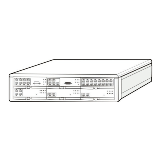
Page 19: Cabinet Configuration
TECHNICAL MANUAL PART 3 MAY 2010 PART 3. INSTALLING AND REPLACING CARDS This section describes how to install and replace various cards of the OfficeServ 7200-S system. 3.1 CABINET CONFIGURATION The OfficeServ 7200-S cabinet has six card slots. Figure 3.1 Front Panel Configuration The following boards may be installed in the cabinet slots according to the configuration of the OfficeServ 7200-S. - Page 20 Table 3.2 Back Panel Parts Parts Description q Power switch Switches the power of OfficeServ 7200-S on/off. w Power connector between a basic Extends 110V AC power from basic cabinet to expansion cabinet and an extension cabinet cabinet. [NOT USED IN THE OS 7200-S SYSTEM] e AC Power Cord “IN”...
-
Page 21: Mp20S Modules
This section describes the procedures for setting switches, installing optional daughter boards, and installing the boards in a slot. The OfficeServ 7200-S MP20S (Main Control Processor) controls the system operation. The MP20S is required for all configurations and goes in slot 0 of the cabinet. - Page 22 The installation procedure for the MP20S card is as follows: 1) Check the exterior of the MP20S card for any damage. If damage is found, do not proceed with installation. Contact Samsung Technical Support. Power the system OFF when installing or removing boards.
-
Page 23: Figure 3.4 Installing The Processor
Figure 3.4 Installing the Processor Board (1) 3) Push the front panel until the board is completely inserted into the OfficeServ 7200-S slot Figure 3.5 Installing the Processor Board (2) 3.2.2 Installing Optional Daughterboards on the MP20S... - Page 24 Home Page OfficeServ 7200-S INSTALLATION TECHNICAL MANUAL PART 3 MAY 2010 serial communication using standard AT commands. When mounting a modem card, the holes on the corners of the modem should be aligned such that the spacer fits in the hole in the following figure.
- Page 25 Home Page OfficeServ 7200-S INSTALLATION TECHNICAL MANUAL PART 3 MAY 2010 A small battery is added to the MP20S card that is called the RTC (real-time clock). The purpose of the battery is to maintain the time, date and day of week information in memory during system powered off conditions.
- Page 26 LAN Port Port for establishing the 10 Base-T/100 Base-Tx Ethernet connection. This allows the MP20S to be connected to a data network. SIO Port Serial port (Samsung use ONLY). RST Button Button for resetting the MP20S card. RUN LED This LED indicates the status of the main CPU operation.
- Page 27 Placing the MP20S SD write protect in the locked position will cause voicemail misoperation and/or system resets. ALWAYS LEAVE SWITCH IN THE UNLOCKED POSITION. The OfficeServ 7200-S Operating System MUST read and write to this media card during normal operation.
-
Page 28: Interface Boards/Cards
The procedure for installing the interface board to each slot is as follows: 1) Check the exterior of the interface board for any damage. 2) Align each interface board to the guardrails of the universal slot of the OfficeServ 7200-S main cabinet, and slide the interface board into the slot. -
Page 29: Replacing Boards
Figure 3.12 Front Panel Lever 3.3.2 Replacing Boards If the OfficeServ 7200-S system fails to operate normally due to an error on the power supply board, control board, or interface board, replace the board with a new one. Removing Cables Replace a board after removing all cables connected to the board. - Page 30 Home Page OfficeServ 7200-S INSTALLATION TECHNICAL MANUAL PART 3 MAY 2010 2) Pull the lever of the board and pull out the target board slowly. Figure 3.14 Removing Board 3) Align the new board to the guardrails of the slot, and slide the new board into the slot. Push the front panel lever of the MP20S card until it is completely inserted into the OfficeServ 7200-S main board port.
- Page 31 LED on the front of the card display the type of service. The first TEPRI/TEPRIa card installed in the OfficeServ 7200-S is the primary source of external clocking. The second TEPRI/TEPRIa installed is the secondary source of external clocking. Default clock selection is first cabinet, left to right then second cabinet.
- Page 32 Home Page OfficeServ 7200-S INSTALLATION TECHNICAL MANUAL PART 3 MAY 2010 **TEPRI: Do not change the settings of DIP switches 3, 5, 6, 7, and 8. Switches 3, 5, 6, and 7 must remain OFF and 8 must be ON.
- Page 33 Network Figure 3.17 Setting Switches on the TEPRIa Board NOTE: T1 and E1 are not supported on the OfficeServ 7200-S. Only PRI is supported. JUMPER SETTING FOR TEPRI The TEPRI board comes from the factory with the following jumper settings. These settings should NOT be changed.
- Page 34 Table 3.6 Ports and LEDs of the TEPRI Ports & LEDs Function Description T1/E1/PRI Ports that connect the T1/E1/PRI cable. Serial port (for Samsung Use ONLY) Button for resetting the TEPRI/TEPRIa board. SYNC LED Clock synchronization. - On: Indicates loss of framing (Error Condition).
- Page 35 Function Description Port for connecting T1/E1/PRI cables Port for connecting to Ethernet (reserved for future use) Serial port for internal Samsung engineering use only. TP1 LED Indicates the type of the circuit connected to port P1 - On: PRI in operation...
- Page 36 Home Page OfficeServ 7200-S INSTALLATION TECHNICAL MANUAL PART 3 MAY 2010 Port, LED Function Description LOS1 LED This LED indicates loss of signal. - On: Signals have been lost, no PCM clocking is being received. - Off: Signals being received (Normal).
- Page 37 Home Page OfficeServ 7200-S INSTALLATION TECHNICAL MANUAL PART 3 MAY 2010 3.3.4 8TRK The 8TRK board provides 8 ports for analog trunk lines with Caller ID capabilities. This board can go into any universal slot (1 ~ 5) in any cabinet. Add as many as needed.
- Page 38 Home Page OfficeServ 7200-S INSTALLATION TECHNICAL MANUAL PART 3 MAY 2010 3.3.5 8TRK2 There are no LEDs on this board compared to the 8TRK card. FRONT VIEW OF 8TRK2 BOARD The front view of the 8TRK2 board is shown in the picture below.
- Page 39 Table 3.10 Ports of the 16DLI2 Ports Function Description P1~P16 Samsung Digital Telephone Extension Port NOTE: A station using KDB-D or KDB-S cannot connect to a port on this board. Refer to Section 7.1.3 (Connecting a Digital Phone) for port Pinout and Wiring. 3.21...
- Page 40 TECHNICAL MANUAL PART 3 MAY 2010 3.3.8 8DLI This board provides 8 ports for connecting Samsung Digital Keysets. This board can go into slots 1~5 of either cabinet. Add as many as needed. SPECIFICATIONS The specifications of the 8DLI/16DLI board are as follows: •...
- Page 41 3.3.9 8COMBO/8COMBO2 These boards provide 8 ports for connecting analog stations and 8 ports for connecting Samsung Digital Keysets. These boards can go into slots 1 through 5 in either cabinet. Add as many as needed. FRONT VIEW OF 8COMBO/8COMBO2 The front view of the 8COMBO and 8COMBO2 boards are shown in the picture below.
- Page 42 Home Page OfficeServ 7200-S INSTALLATION TECHNICAL MANUAL PART 3 MAY 2010 3.3.10 16SLI2/16MWSLI These boards provide 16 ports for connecting analog stations. It can go into slots 1 through 5 in the cabinet. Add as many as needed. These cards automatically detect DTMF or dial pulse signals from the SLT.
- Page 43 Home Page OfficeServ 7200-S INSTALLATION TECHNICAL MANUAL PART 3 MAY 2010 3.3.11 8SLI/8SLI2 This board provides 8 ports for connecting analog stations. It can go into slots 1 through 5 of either the main cabinet. Add as many as needed. This card automatically detects DTMF or dial pulse signals from SLT.
- Page 44 Ethernet (IEEE 802.3af). This means that it can provide power to any IEEE 802.3af compliant device that is connected to any of its Ethernet ports. All Samsung IP phones and SMT-R2000 Dual-Band APs can receive power when connected to PLIM. When connected to the PLIM Ethernet port, these devices no longer need the AC power adapter.
- Page 45 Section 5.3, CONNECTING THE OS7150 EXTERNAL PoE PSU SUPPLEMENTAL POWER SUPPLY for further information. Refer to the OfficeServ 7200-S Data Server Manual for detailed PLIM installation and configuration information. It is important to note that the OS7150 only provides additional power to the PLIM/PLIM2.
- Page 46 Home Page OfficeServ 7200-S INSTALLATION TECHNICAL MANUAL PART 3 MAY 2010 FRONT VIEW OF PLIM The front view of the PLIM module is shown in the picture below. Figure 3.31 Front View of the PLIM The front panel components of the PLIM have the functions below: Table 3.14 Ports and LEDs of the PLIM...
- Page 47 Home Page OfficeServ 7200-S INSTALLATION TECHNICAL MANUAL PART 3 MAY 2010 3.3.13 PLIM2 (PoE LAN INTERFACE MODULE) PoE LAN Interface Module (PLIM2) can use Power Supply Unit (PSU) or an external rectifier and selects the power supply source by using shunt pins.
- Page 48 Home Page OfficeServ 7200-S INSTALLATION TECHNICAL MANUAL PART 3 MAY 2010 • For the use of an external rectifier: The shunt pins (J2, J3 and J4) are connected between pin 2 and pin 3. There is no restriction on the use of an external rectifier because each of them can supply the current of 10 A.
- Page 49 Home Page OfficeServ 7200-S INSTALLATION TECHNICAL MANUAL PART 3 MAY 2010 Specification The specification of the GPLIMT data board is as follows. 12 10/100 Base-T interface port 2 10/100/1000 Base-TX interface port 1 Serial console port (also used as P12) ...
- Page 50 Home Page OfficeServ 7200-S INSTALLATION TECHNICAL MANUAL PART 3 MAY 2010 Ports & LEDs Function Description Right LED of P1~P6 First LED: Indicates if the P7~P12's link is operating - On: When the link is operating, LED is turned on into green color...
- Page 51 OAS card, so a maximum of 16 MOBEX DTMF receivers per card is possible. All other slots allow up to 32 MOBEX receivers per card. • Up to 3 OAS cards can be installed in the OfficeServ 7200-S. • When installed in a 16 timeslot position, the following card slot must be empty.
- Page 52 Table 3.17 OAS Front Panel Components Ports & LEDs Function Description Port that connects the Ethernet. Serial Port (for Samsung Use ONLY) Button for resetting the OAS. PWR LED This LED indicates the power supply status. - Off: Power is not being supplied.
-
Page 53: Daughtercard Modules
Home Page OfficeServ 7200-S INSTALLATION TECHNICAL MANUAL PART 3 MAY 2010 3.3.16 INSTALLING UNI CARDS AND DAUGHTERCARD MODULES The UNI card is a universal base carrier card that can accommodate up to 3 optional daughtercards. The UNI card by itself serves no function. The UNI card can be installed in slot 1 thru slot 5 of the main cabinet. - Page 54 Home Page OfficeServ 7200-S INSTALLATION TECHNICAL MANUAL PART 3 MAY 2010 Older boards need to be shipped to Repair for Free Upgrade The front view of the UNI card is shown in the picture below. Figure 3.37 Front View of UNI Card Table 3.18 UNI Card Ports and LEDs...
- Page 55 Home Page OfficeServ 7200-S INSTALLATION TECHNICAL MANUAL PART 3 JANUARY 2011 3.3.22 CONFERENCE CARD (CNF24) --For More Information Refer to CNF24 Technical Manual The CNF24 provides 24 ports of voice conference services per card and supports transceiver function of packet data converted from voice data through the data network. The users can be internal and external participants using SIP trunks, PRI trunks, and SPNet trunks.
- Page 56 Home Page OfficeServ 7200-S INSTALLATION TECHNICAL MANUAL PART 3 JANUARY 2011 Table 3.19 CNF24 Front Panel Components Ports & LEDs Function Description Port that connects the Ethernet. Connector: RJ45 Cable: CAT 5 cable, UTP. UART Port (For Testing Only). Serial Port.
-
Page 57: System Capacity
SYSTEM CAPACITY The CNF24 has 24 conference channels and a maximum of 1 card can be installed on the OfficeServ 7200-S system. When recording and/or paging features are used the number of conference members allowed to attend the conference is decreased since the recording and paging features occupy one conference channel each. - Page 58 Home Page OfficeServ 7200-S INSTALLATION TECHNICAL MANUAL PART 3 JANUARY 2011 SLOT INFORMATION If the CNF24 card is installed on a slot that supports more than 24 channels, all 24 conference channels are used. If installed on a 16 channel slot, only 16 conference channels are supported.
- Page 59 Figure 3.41 Input Service License Key CNF24 LICENSE A license per channel is required to use the conference service. The maximum number of channels allowed per OfficeServ 7200-S system is 24 (1 CNF24 cards x 24 channels). Figure 3.42 CNF24 License...
- Page 60 Home Page OfficeServ 7200-S INSTALLATION TECHNICAL MANUAL PART 3 JANUARY 2011 UPDATING CNF24 SETUP INFORMATION Each CNF24 card has a unique MAC address, and the OfficeServ system uses the MAC address to manage the card information. If the card location is changed, the user is required to update the setup information as follows: 1.
- Page 61 Home Page OfficeServ 7200-S INSTALLATION TECHNICAL MANUAL PART 3 JANUARY 2011 UPGRADING CNF24 CARD SOFTWARE To upgrade CNF24 software follow the steps below: 1. Select the [Util] menu option. 2. Select Package Update. Conference Card Package Update window displays. Figure 3.43 CNF24 Package Update 3.
- Page 62 TECHNICAL MANUAL PART 3 MAY 2010 3.4 DAUGHTERCARD MODULES There are 5 different daughtercards available on the OfficeServ 7200-S: 1) 4SWM (installed on MP20S): 4 port layer 2 LAN switch when installed on the MP20S PoE is not available. 2) Modem Daughtercard (Installed on MP20S only): Provides modem communication for the OfficeServ 7200-S system.
- Page 63 Home Page OfficeServ 7200-S INSTALLATION TECHNICAL MANUAL PART 3 MAY 2010 The 4SWM is shown in the figure below: Figure 3.45 4SWM NOTE: When installed on the MP20S, PoE is not available from system power supply. AC adapter or external PoE switch is required.
- Page 64 LAN/WAN connection is unavailable. The modem board has the following functions: The modem board operates in OfficeServ 7200-S via V.24 interface. In addition, the modem board supports the V.90 protocol. The OfficeServ 7200-S controls the modem board via serial communication using standard AT commands.
- Page 65 Home Page OfficeServ 7200-S INSTALLATION TECHNICAL MANUAL PART 3 MAY 2010 3.4.3 4TRM (4 Port Loop Start Trunk Interface Module) This daughtercard provides 4 loop start trunk interface ports to connect to loop start analog trunk lines with Caller ID.
- Page 66 PART 3 MAY 2010 3.4.4. 4DLM (4 Port Digital Phone Interface Module) This daughtercard provides 4 ports for connecting Samsung Digital Keysets. It can be installed on the UNI card only in any of the UNI card daughtercard positions. Add as many as needed.
- Page 67 Home Page OfficeServ 7200-S INSTALLATION TECHNICAL MANUAL PART 3 MAY 2010 3.4.5 4SLM (4 Port Single Line Telephone Interface Module) This daughtercard provides 4 ports for connecting analog telephones. It also provides the message waiting lamp functionality for phones supporting this feature. It can ONLY be installed on the UNI card in any of the UNI card daughtercard positions.
-
Page 68: Connecting Power Fail Transfer
1 on the 8SLI/8SLI2, 16SLI2, or 16MWSLI cards. In case the OfficeServ 7200-S loses power from its AC source, and no battery backup is available, this feature is automatically activated. The SLT connected to Port 1 of the SLI will get C.O. -
Page 69: Connecting External Batteries
OfficeServ 7200-S to emergency backup batteries. The OfficeServ 7200-S can also run without AC power on a -48VDC battery system or rectifier. There should be no more than a 0.5VDC drop in voltage from the OfficeServ 7200-S and the batteries. - Page 70 The procedure for using a battery cable to connect an external battery to the OfficeServ 7200- S system is as follows: 1) Prepare the battery cable that was provided with the OfficeServ 7200-S system. An end of this battery cable consists of a white wire and a black wire.
- Page 71 Home Page OfficeServ 7200-S INSTALLATION TECHNICAL MANUAL PART 4 MAY 2010 Figure 4.2 Connecting an External Battery (2)
-
Page 72: Before Connecting Power
• System should be grounded as described in Part 1.2 and Part 2.5. 5.2 PROCEDURE FOR CONNECTING POWER SINGLE CABINET CONFIGURATION Use the power cable provided with the OfficeServ 7200-S system to connect the input power terminal on the rear panel of the cabinet to a grounded outlet. Figure 5.1 Connecting Power... -
Page 73: Supply
The OfficeServ 7150 PoE PSU provides additional power to your OfficeServ 7200-S cabinets when the internal OfficeServ 7200-S PSU limits have been exceeded. It is composed of a cabinet which can accomodate up to two POE-M Power supply modules. Each module provides -54V, 7.5A. - Page 74 Home Page OfficeServ 7200-S INSTALLATION TECHNICAL MANUAL PART 5 MAY 2010 The following chart provides current ratings for various devices connected to the system: Table 5.1 Consumption per Device Connected Current Consumption Card Name Device Type per Each Device (mA)
-
Page 75: Grounding Requirements
Home Page OfficeServ 7200-S INSTALLATION TECHNICAL MANUAL PART 5 MAY 2010 PRODUCT SAFETY Electric Shock Make sure to turn this product OFF when handling this product. Handling this product with AC power ON may cause electric shock. Grounding Requirements •... - Page 76 Home Page OfficeServ 7200-S INSTALLATION TECHNICAL MANUAL PART 5 MAY 2010 FOLLOW ALL SAFETY AND GROUNDING GUIDELINES MENTIONED IN SECTIONS 1.1.1 and 1.2. OFFICESERV 7150 FRONT VIEW Front view of the OfficeServ 7150 cabinet is as shown in the following illustration. The cabinet consists of two slots and one distributor.
- Page 77 • Battery cable 1 each • AC Power cable(110V Type) 1 each • Alarm cable 1each (not used for OfficeServ 7200-S systems) • 19" Rack mount kit 1set The POE-M PSU modules are sold separately. Extra PoE cables can be purchased if needed.
-
Page 78: Installation Procedure
Home Page OfficeServ 7200-S INSTALLATION TECHNICAL MANUAL PART 5 MAY 2010 GROUNDING CONDITIONS Observe the following requirements when OfficeServ 7150 PoE is grounded. • The grounding wire of OfficeServ 7150 PoE shall be connected to the ground through a qualified grounding media. -
Page 79: Tools Required
Home Page OfficeServ 7200-S INSTALLATION TECHNICAL MANUAL PART 5 MAY 2010 Do not remove a blanking plate from unused slots. 3) Insert the PoE-M module into the slot. 4) Connect an external battery with proper capacity if required. 5) Connect AC input voltage. - Page 80 Home Page OfficeServ 7200-S INSTALLATION TECHNICAL MANUAL PART 5 MAY 2010 1) Attach the cross bar bracket bracket to the bottom of OfficeServ 7150 PoE, and tighten with three screws. Figure 5.6 OS 7150 Installation in a Rack (1) 2) Attach the rack mount brackets to both sides of the rack, and tighten with six screws.
- Page 81 Home Page OfficeServ 7200-S INSTALLATION TECHNICAL MANUAL PART 5 MAY 2010 3) Guide the OS 7150 unit through the guide rails formed by the rack mount brackets. Figure 5.8 OS 7150 Installation in a Rack (3) 4) Match the cross bar bracket attached to the 7150 to the two holes in the bracket inside the rack properly and then tighten with screws.
-
Page 82: Ground Wire Connection
Home Page OfficeServ 7200-S INSTALLATION TECHNICAL MANUAL PART 5 MAY 2010 INSTALLATION ON THE FLOOR Observe the following requirements to install OfficeServ 7150 on the floor: • Install the system at a place with good air ventilation and no humidity. -
Page 83: Connecting Power
• Disconnect and turn off all power to the 7150 before connecting the battery. • Disconnect any connections to an OfficeServ 7200-S system. • Pay attention to polarity (+,-) orientation of the battery when connecting to the system. 1) A battery cable comes with the OfficeServ 7150 cabinet. One end of the battery cable is a green keyed plastic connector. - Page 84 Home Page OfficeServ 7200-S INSTALLATION TECHNICAL MANUAL PART 5 MAY 2010 Safety Tips in Connecting External Battery Cable As the OfficeServ 7150 is a high output power supply system, a maximum of DC48V 30A may be flown from the battery. Do not use cables other than the one that comes with this product.
- Page 85 GND lug from the left on the back of the 7150. Connect the Blue wire to the first -54V lug from the left on the back of the 7150. 4) If connection to a second OfficeServ 7200-S cabinet is required, then repeat the steps above and connect the red wire to the 2 GND lug from the left and the blue wire to the second +54V lug from the left.
- Page 86 Home Page OfficeServ 7200-S INSTALLATION TECHNICAL MANUAL PART 5 MAY 2010 SPECIFICATIONS OF OFFICESERV 7150 Specifications of Cabinet Table 5.2 Input Voltage and Frequency INPUT VOLTAGE & FREQUENCY Rated AC Input Voltage Single phase AC 110/220VAC Range of Allowable AC Input Voltage...
-
Page 87: Safety Precautions
TECHNICAL MANUAL PART 6 MAY 2010 PART 6. CONNECTING C.O. LINES This section describes how to connect C.O. lines to the OfficeServ 7200-S system after installation. 6.1 SAFETY PRECAUTIONS To reduce the risk of personal injury, follow these precautions before connecting TELCO circuits: •... -
Page 88: Connecting C.o. Lines
TEPRI/TEPRIa boards can be connected to a PRI C.O. circuit through a RJ-45 port. As show below, connect a T1/PRI circuit to the PRI port of the OfficeServ 7200-S system. Though the TEPRI/TEPRIa board supports E1 & T1, it is not used in this product. - Page 89 Home Page OfficeServ 7200-S INSTALLATION TECHNICAL MANUAL PART 6 MAY 2010 ORDERING A PRI The following information may be useful when ordering PRI service from the telephone company. PARAMETERS supported on OfficeServ TEPRI cards used for PRI service only. FRAMING...
-
Page 90: Connecting Stations
PART 7. CONNECTING STATIONS AND ADDITIONAL EQUIPMENT This section describes how to connect various stations and additional equipment, such as analog/digital phones, door phones and door locks, to the OfficeServ 7200-S system. 7.1 CONNECTING STATIONS 7.1.1 Safety Precautions To reduce the risk of personal injury, follow these precautions before connecting telephone circuits: •... - Page 91 7.1.2 Connecting an Analog Phone Connect an analog phone to the 4SLM, 8SLI/8SLI2, 16SLI2, 16MWSLI, 8COMBO/8COMBO2 boards installed in the OfficeServ 7200-S system. CONNECTING TO THE 8SLI/8SLI2 Connect an analog phone to the 8SLI/8SLI2 board by using a twisted pair of AWG #24 or AWG #26 wire.
- Page 92 Home Page OfficeServ 7200-S INSTALLATION TECHNICAL MANUAL PART 7 MAY 2010 CONNECTING TO THE 8COMBO/8COMBO2 Connect an analog phone to the 8COMBO/8COMBO2 board by using a twisted pair of AWG #24 or AWG #26 wires. S1-S8 Port (RJ-45) S1-S8 Port Pin No.
- Page 93 CAUTION: The input power of the SMT-i Series phones needs 5.0vDC and 3000mA. The SMT-i5210, SMT- i5220, SMT-i5230, and SMT-i5243 need to be powered by using Samsung’s SMT-A53PW power adapter. The SMT-i3105 requires the SMT-A53PA power adapter. Failure to use the appropriate power supply will cause permanent damage to the phone and will void Samsung’s warranty.
- Page 94 • MP20S-LAN port 7.1.7 Connecting a Door Phone and a Door Lock Connect a door phone and a door lock to the OfficeServ 7200-S system using a Door Phone Interface Module (DPIM). Connect the Door Phone Interface Module (DPIM) line jack to any DLI port in the OfficeServ 7200-S system using twisted pair (24AWG/26AWG).
- Page 95 Home Page OfficeServ 7200-S INSTALLATION TECHNICAL MANUAL PART 7 JULY 2010 Figure 7.8 Connecting a Door Phone and a Door Lock...
- Page 96 Home Page OfficeServ 7200-S INSTALLATION TECHNICAL MANUAL PART 7 MAY 2010 7.1.8 Wall-Mounting Keysets HOLES FOR MOUNTING SCREWS NOTE: THE DIRECTORY CARD SLIDE TRAY IS NOT Figure 7.9 Wall-Mounting a Keyset iDCS keysets come equipped with a reversible base wedge. To wall-mount a keyset, remove the wedge from the keyset and remove the directory tray from the wedge.
- Page 97 Home Page OfficeServ 7200-S INSTALLATION TECHNICAL MANUAL PART 7 MAY 2010 USED FOR ATTACHING AOM OR 64B MODULE WITH CONNECTOR CLIP HOLES FOR MOUNTING SCREWS NOTE: THE DIRECTORY CARD SLIDE TRAY IS NOT Figure 7.10 Ultra Base Wedge WALL-MOUNTING KEYSETS WITH ULTRA BASE WEDGE The keysets now come equipped with a new Ultra Base wedge.
- Page 98 Home Page OfficeServ 7200-S INSTALLATION TECHNICAL MANUAL PART 7 MAY 2010 Use screw holes 1 and 3 to attach to a standard telephone wall-mount plate with locking pins. This method can cause the keyset to wobble as the keyset feet do not fit securely to the mounting surface.
- Page 99 Home Page OfficeServ 7200-S INSTALLATION TECHNICAL MANUAL PART 7 MAY 2010 BASE STAND SLOTS SCREW HOLES BASE STAND HANDSET HANDSET RETAINING CLIP RETAINING CLIP IN WALL-MOUNTING IN DESKTOP POSITION POSITION FIGURE 6 Figure 7.12 Wall-Mounting DS 5000, ITP-5121D and ITP-5107S Keysets WALL-MOUNTING SMT-i5200 KEYSETS Assemble the wall-mount bracket where you want to use the phone.
- Page 100 Home Page OfficeServ 7200-S INSTALLATION TECHNICAL MANUAL PART 7 MAY 2010 2. Remove the desk cradle of the phone. a. Fix one latch of the cradle to the top or bottom groove of the phone. b. Push the remaining latch into the remaining groove on the opposite side.
- Page 101 Home Page OfficeServ 7200-S INSTALLATION TECHNICAL MANUAL PART 7 MAY 2010 To detach the wall-mounting bracket follow the steps below: You can detach the phone from the bracket by pressing the [Push] section at the bottom of the bracket. Detach the phone more easily by pulling the entire bottom of the bracket instead of only the [Push] section.
- Page 102 Home Page OfficeServ 7200-S INSTALLATION TECHNICAL MANUAL PART 7 MAY 2010 2. Remove the cradle of the phone by pressing the [Push] mark on the top of the cradle to push it out 3. Use screw holes 1 and 2 to attach the base wedge to a standard electrical outlet box.
- Page 103 Home Page OfficeServ 7200-S INSTALLATION TECHNICAL MANUAL PART 7 MAY 2010 64 BUTTON MODULES Using one pair twisted #24 AWG or #26 AWG jumper wire, cross-connect each 64 button module (64 BM) to the DLI port or plug into the KDb-DLI of your choice (see part 7.1.8 of this...
- Page 104 Home Page OfficeServ 7200-S INSTALLATION TECHNICAL MANUAL PART 7 MAY 2010 ATTACHING DCS 32 BUTTON AOM AND DCS 64B MODULES WITH MASTER STATION These new Ultra Base Wedges allow a connector clip (packaged with 64B Modules and AOMs) to be connected to the underside of the new style wedge and attach AOM(s) or 64B module(s) together with the main or “master”...
- Page 105 Home Page OfficeServ 7200-S INSTALLATION TECHNICAL MANUAL PART 7 MAY 2010 ATTACHING iDCS 64 BUTTON MODULES TO AN iDCS KEYSET First remove the base wedge from the iDCS 64 Button Module and attach the bracket to it with two of the screws provided (see Figure 7.15).
- Page 106 Home Page OfficeServ 7200-S INSTALLATION TECHNICAL MANUAL PART 7 MAY 2010 Figure 7.16 Attaching the iDCS 64 Button Module to an iDCS Keyset ATTACHING iDCS 14 BUTTON MODULES TO AN iDCS KEYSET To add an iDCS 14 Button Key Strip to your iDCS keyset, follow these steps (see Figure 7.17).
- Page 107 Home Page OfficeServ 7200-S INSTALLATION TECHNICAL MANUAL PART 7 MAY 2010 REMOVE KNOCKOUTS Figure 7.17 Attaching iDCS 14 Button AOM to an iDCS Keyset ATTACHING DS 64 BUTTON MODULES TO a DS 5021D or a DS 5014D KEYSET First attach the bracket to the keyset with two of the screws provided. Then attach the 64 button add-on module to the bracket with the remaining two screws.
- Page 108 Home Page OfficeServ 7200-S INSTALLATION TECHNICAL MANUAL PART 7 MAY 2010 SMT-i5264 ADD ON MODULE The SMT-i5264 module can be used beside any ITP 5100 keysets, SMT-i Series, and TDM phones. The cosmetic design matches the SMT-i 5000 Series phones. The SMT-i5264 Add On Module only attaches to SMT-i5200 Series.
- Page 109 Home Page OfficeServ 7200-S INSTALLATION TECHNICAL MANUAL PART 7 MAY 2010 SETTING-UP SMT-i5264 AOM SMT-i5264 AOM will register to the OfficeServ system as an IP phone device. It need the IP phone ID and password during the registration. The SMT-i5264 will receive an IP phone extension.
- Page 110 Home Page OfficeServ 7200-S INSTALLATION TECHNICAL MANUAL PART 7 MAY 2010 o Server IP Address: (OfficeServ IP address from MMC 830) o (use navigation key to move to the following fields) o Server ID: (ITP ID from MMC 840) o Server Password: (ITP password from MMC 840)
- Page 111 Home Page OfficeServ 7200-S INSTALLATION TECHNICAL MANUAL PART 7 MAY 2010 7.1.9 Connecting the SMT-A52GE Gigabit Adaptor The Gigabit Adaptor processes the Gigabit data for a Gigabit LAN connection on the PC connected to the SMT-i5200 series IP phone. COMPONENTS...
- Page 112 Home Page OfficeServ 7200-S INSTALLATION TECHNICAL MANUAL PART 7 MAY 2010 HOW TO CONNECT TO A PHONE 1. Separate the cradle at the back of the phone. 2. Mount the Gigabit Adaptor onto the back of the body. NOTE: The back of the Gigabit Adaptor is sharp, so take care to avoid injury.
- Page 113 Home Page OfficeServ 7200-S INSTALLATION TECHNICAL MANUAL PART 7 MAY 2010 3. Connect the cable. When PoE is supplied via the LAN: Handset Headphones Network (PoE Switch) When PoE is not supplied via the LAN: Power Handset Headphones Network 4. Attach the cradle to the back of the phone.
-
Page 114: Connecting A Wireless Lan Access Point
INSTALLATION TECHNICAL MANUAL PART 7 MAY 2010 7.1.10 Connecting a Wireless LAN Access Point Wireless LAN service offered by the OfficeServ 7200-S system requires the following equipment: 1. SMT-R2000: Wireless LAN Access Point (AP) 2. SMT-W5100E/SMT-W5120D: Wireless LAN IP Phone Table 7.2 Specification for Wireless LAN Connection... - Page 115 Home Page OfficeServ 7200-S INSTALLATION TECHNICAL MANUAL PART 7 MAY 2010 SMT-R2000 AP MP20S Wireless Handset Figure 7.22 Connecting Access Point to Ethernet Port AC Power Connect the access point by using two 0.64 mm twisted cables (RJ-45 Ethernet cable, 600 m/1968 ft maximum distance) or two 0.40 mm twisted cables (RJ-45 Ethernet cable,...
-
Page 116: Connecting Additional Equipment
Internal Modem 7.2.1 Connecting MOH/BGM Equipment The OfficeServ 7200-S system offers Music on Hold. The system provides internal tone/music and external music sources per C.O. or extension lines as the music source. One external MOH source connection is provided on the MP20S MISC port. Connect the music source to this MISC port of the MP20S card. - Page 117 Instead of an internal speaker, external broadcasting equipment, such as amps or speakers, and additional equipment that can broadcast page ring) signals outside a building can be connected to the OfficeServ 7200-S system. Connect external/additional paging equipment to the MP20S MISC port. The power of the external/additional paging equipment should be connected separately.
-
Page 118: Loud Bell Interface
Home Page OfficeServ 7200-S INSTALLATION TECHNICAL MANUAL PART 7 MAY 2010 HARDWARE MISC DEFAULT ITEM FUNCTION # in MMC 724 DN (Ports) Page Tip & Ring (600 ohms) Contact Pair #1 Contact Pair #2 • MISC port is located on the front panel of the MP20S. -
Page 119: Connecting Common Bell
FUNCTION # in MMC 724 03 or 04 362 or 363 The OfficeServ 7200-S system supports only one dry contact for the common bell. The MISC port is located on the front panel of the MP20S. Dry contact (For common bell) Figure 7.26 Connecting Common Bells... -
Page 120: Ring Over Page
1Gb or higher CONNECTING INSTALLATION TOOL (OIT) TO LAN PORT The OIT application can communicate to the OfficeServ 7200-S system via the LAN or MODEM connection. The OIT can connect to the MP20S via LAN connection using a customer provided LAN switch or using the 4SWM module or PLIM/PLIM2 module as shown in Figure 7.27. - Page 121 Home Page OfficeServ 7200-S INSTALLATION TECHNICAL MANUAL PART 7 MAY 2010 MP20S Installation Tool Figure 7.27 OIT Connection to LAN Port NOTE: Installation Tool must be version 1.43A or higher. Detail procedures for each of the steps above are as follows: SETTING NETWORK PARAMETERS THROUGH MMC 830 Set the network parameters of the system.
- Page 122 10. Click [OK]. Click [Close]. 11. Click [System]. Click [Connect]. 12. Enter Password [Samsung], then [OK]. INSTALLATION TOOL AND MODEM CONNECTION VIA TELCO LINE This example is based on a PC using an internal modem card. Connect Telephone line cord from internal modem connection of PC directly to loop start telco line.
- Page 123 12. Click [OK]. Click [Close]. 13. Click [System]. Click [Connect]. 14. Enter Password [Samsung], then [OK]. NOTE: Internal modem card must be installed for the connection to work. The incoming telco line may need to be programmed to ring directly to modem port of OfficeServ 7200-S system in MMC 406 (e.g.
- Page 124 Home Page OfficeServ 7200-S INSTALLATION TECHNICAL MANUAL PART 7 MAY 2010 7.2.8 Device Manager (DM) Tool The OfficeServ Device Manager is a Windows™ application that allows programming of the OfficeServ™ 7000 Series phone systems from a PC over a data network or modem. The Device Manager allows access to OfficeServ™...
-
Page 125: Minimum Requirements
Home Page OfficeServ 7200-S INSTALLATION TECHNICAL MANUAL PART 7 MAY 2010 • Compare Databases The Database Compare function helps you track changes between archives by detecting and displaying any differences between two saved databases. • Store Programming Favorites Bookmarks increase efficiency by allowing you to save a list of commonly used programming screens. - Page 126 Home Page OfficeServ 7200-S INSTALLATION TECHNICAL MANUAL PART 7 MAY 2010 Client Application: The client application can be used on OfficeServ 7000 series systems using software version 4.51 and lower. LAUNCHING DEVICE MANAGER Before you can successfully access an OfficeServ System using the embedded Device Manager via a web browser, there are a few things that need to be set or verified.
- Page 127 Home Page OfficeServ 7200-S INSTALLATION TECHNICAL MANUAL PART 7 MAY 2010 3. Java Plug-In Java Web Start Plugin should be installed to use OfficeServ DM. If it’s not, you will be prompted to download it when you attempt to launch Device Manager.
- Page 128 Home Page OfficeServ 7200-S INSTALLATION TECHNICAL MANUAL PART 7 MAY 2010 5. Ports When using a public network to access an OfficeServ system with Device Manager, firewall ports 80 and 21 must be opened on the router. Figure 7.34 Firewall Ports CONNECTING TO THE EMBEDDED DEVICE MANAGER Device Manager is launched with a web browser.
- Page 129 You may see the following warning screen. Simply click on the Run option if you do. Figure 7.36 Security Warning Device Manager will open in a separate window. This may take up to 15 seconds to open. The default Login ID is admin and the default password is samsung. Figure 7.37 DM Login Page 7.40...
- Page 130 LAUNCHING THE OFFICESERV DEVICE MANAGER CLIENT APPLICATION Unzip the file obtained from the Samsung GSBN website. The zip file will contain one file - OSDM.JAR file. This is the file used to launch Device Manager. For ease of use, we recommend placing this file on your desktop.
- Page 131 Home Page OfficeServ 7200-S INSTALLATION TECHNICAL MANUAL PART 7 MAY 2010 LINK SETUP The Link Setup window is a connection manager for your OfficeServ system connections. You must enter a site into the Site list before connecting to an OfficeServ System.
- Page 132 Home Page OfficeServ 7200-S INSTALLATION TECHNICAL MANUAL PART 7 MAY 2010 Default Port sets the IP connection ports to use for this site. The default is 5090 for programming and 5003 for Media Card access. To set new values you must uncheck the Default Port checkbox.
- Page 133 Home Page OfficeServ 7200-S INSTALLATION TECHNICAL MANUAL PART 7 MAY 2010 2. Modem Options The Modem Options tab allows you to set configuration parameters for MODEM connections. Once changes have been made you must click [Apply] to save them. Figure 7.41 MODEM Options •...
- Page 134 Home Page OfficeServ 7200-S INSTALLATION TECHNICAL MANUAL PART 7 MAY 2010 CONNECT TO AN OFFICESERV SYSTEM USING THE CLIENT APPLICATION There are a couple of different methods you can use to connect to a system: 1. Click on [System] [Connect].
- Page 135 You’ll be prompted to enter the ID and password. Default values are: • ID = Admin • Password = samsung Figure 7.44 DM Login Page Please refer to the OfficeServ Device Manager User Manual for detailed instructions on how to use Device Manager.
- Page 136 Figure 7.45 Connecting SMDR and Printer 7.2.8 OfficeServ 7200-S and ANALOG TERMINAL ADAPTERS (ATAs) The OfficeServ 7200-S can be SIP enabled (SIP licenses required) to interface with other 3 party analog terminal adapters (ATA) devices, to provide voice connectivity to a VoIP network.
-
Page 137: Starting The System
TECHNICAL MANUAL PART 8 MAY 2010 PART 8. POWER UP PROCEDURES This section describes items to check before starting the OfficeServ 7200-S system and the procedure for starting the system. 8.1 PRE-CHECK This section describes items to check before starting the OfficeServ 7200-S system. -
Page 138: Checking The Fan
10) If the LED status of the MP20S or interface board is abnormal, turn off the power of the cabinet and turn the power on again. If this does not restore normal system operation contact Samsung Technical Support. 8.3 CHECKING THE FAN When the system fan is not operating, the 48 DC power and the system operation will be turned off to prevent system overheating. -
Page 139: Numbering Extensions And C.o. Lines
PART 8 MAY 2010 8.4 NUMBERING EXTENSIONS AND C.O. LINES Once the OfficeServ 7200-S system is booted, the MP20S card verifies the boards mounted on each slot and saves this information as the default configuration of the system. According to the setting of the S3 switch (SW6, SW7, SW8) of the MP20S card, the OfficeServ 7200-S system assigns 3 or 4 digits to C.O. -
Page 140: Database Management
MANAGEMENT 9.1 SOFTWARE MANAGEMENT WITH MP20S INSTALLED The OfficeServ 7200-S operating software, Voicemail/Auto Attendant software, and all saved messages and greetings are stored on the MP20S SD card which is inserted into the Media Card slot on the MP20S. The MP20S SD card has 1G of flash memory and is formatted, with a custom format to allow faster loading, in a similar manner to a hard disk. - Page 141 Home Page OfficeServ 7200-S INSTALLATION TECHNICAL MANUAL PART 9 MAY 2010 OfficeServ Installation Tool it can be uploaded into SRAM using the Utility menu in Installation Tool. Database changes are copied from SRAM to NAND flash every 5 minutes or immediately after setting programming to “Disabled”...
-
Page 142: Adding Stations And Trunks
PART 10. ADDING CARDS TO THE SYSTEM 10.1 ADDING STATIONS AND TRUNKS 1) Power the OfficeServ 7200-S OFF before adding a new board. Locate a compatible empty card slot. Pull the ejector handle forward, then insert the new card into the slot and push firmly in the middle of the card ejector to ensure that it is fully inserted into the back plane connector.
Need help?
Do you have a question about the OfficeServ 7200-S and is the answer not in the manual?
Questions and answers