Table of Contents
Advertisement
Advertisement
Table of Contents

Related Manuals for CAS PD-II


Summary of Contents for CAS PD-II
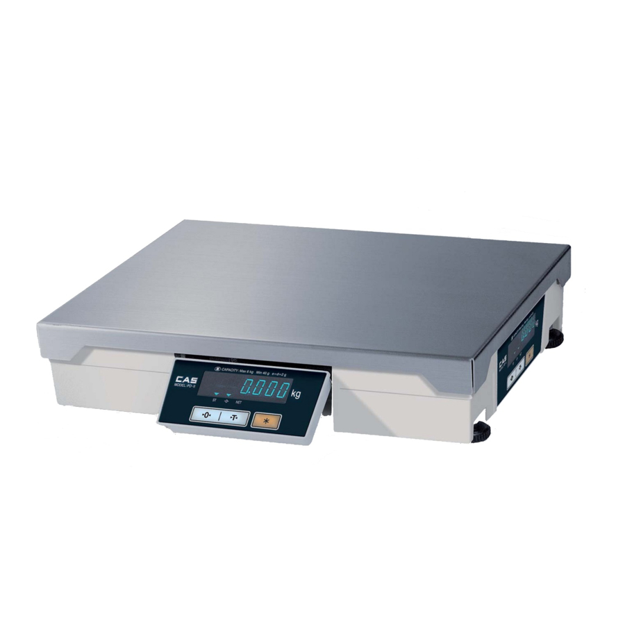
- Page 1 PD-II MANUAL...
-
Page 2: Table Of Contents
< Table of Contents > 1. Introductions ........................4 1.1. The Preface.....................4 1.2. Precautions .....................4 1.3. Specifications (CE) ..................5 1.4. Sealing Method ....................7 2. Calibration Mode ......................8 2.1. How to Go to Normal mode (C – 0) ..............9 How to Confirm Span Calibrated A/D Value(C – 1) .........9 2.2. - Page 3 4.1. System Block Diagram ..................32 4.2. Circuit Diagram....................33 4.2.1. Main......................33 4.2.2. Power .......................34 4.2.3. Display......................35 4.2.4. Communication (Serial and Parallel) ..........36 4.3. Wiring Diagram....................37 4.4. Parts Location ....................38 4.4.1. Main and Power Part ................38 4.4.2. Display Part ....................39 5. EXPLODED VIEW.......................41 6.
-
Page 4: Introductions
1.2. Precautions To ensure that you get the most from your scale, please follow these instructions. 1. Do not disassemble the scale. When any damage or defect occurs, contact your CAS authorized dealer immediately for proper repair. 2. Do not overload beyond the maximum weight limit. -
Page 5: Specifications (Ce)
1.3. Specifications (CE) MODEL PDII – 6kg PDII – 15kg PDII – 30kg PDII-60kg Single Interval Single Interval Single Interval Single Interval CAPACITY 6 kg 15 kg 30 kg 60 kg INTERNAL 1 / 90,000 1 / 90,000 1 / 90,000 1 / 90,000 RESOLUTION EXTERNAL... - Page 6 Pound(lb) Version (UL) MODEL PD2 – 15LB PD2 – 30LB PD2 – 60LB PD2-150LB Single Interval Single Interval Single Interval Single Interval 15 lb / 0.005 lb 30 lb/ 0.01 lb 60 lb/ 0.02 lb 150 lb / 0.05 lb Capacity Dual Interval Dual Interval...
-
Page 7: Sealing Method
1.4. Sealing Method... -
Page 8: Calibration Mode
2. Calibration Mode To go to calibration mode, turn on the power while pressing the calibration switch. The display shows “CAL” three times, and then “C-0”. Mode Selection : [TARE] or [UNIT] key Enter : [ZERO] key MODE DESCRIPTION Normal Mode C –... -
Page 9: How To Go To Normal Mode (C - 0)
2.1. How to Go to Normal Mode (C – 0) To go to calibration mode, turn on the power while pressing the calibration switch. The display shows “CAL” three times, and then “C-0”. To go to Normal mode, press the [ZERO] key. How to Confirm Span Calibrated A/D Value(C –... -
Page 10: Span Calibration(C - 3)
2.2. Span Calibration(C – 3) (1) To go to calibration mode, turn on the power while pressing the calibration switch. The display shows “CAL” three times, and then “C-0”. (2) Press the [TARE] key until the display shows “C – 3”. (3) Press the [ZERO] key, the display shows “UnLOAd”. -
Page 11: Capacity Display And Option Setting(C - 4)
2.3. Capacity Display and Option Setting(C – 4) For pariculars please inquire at CAS . Key operation : ◆ Press the ZERO key to enter setting value. ◆ Press the TARE key to change digit position. ◆ Press the lb/kg (* )key to have number Up. -
Page 12: Save Setting(C-4-4)
2.3.5. Save Setting(C–4–4) UNIT CHANGE 1: Possible 0: Impossible If NTEP(C-4-1 3 bit) is set, C-4-4 Setting don’t care. 2.4. Averaging A/D Value(C - 5) (1) To go to calibration mode, turn on the power while pressing the calibration switch. The display shows “CAL”... -
Page 13: Gravity Constant (C - 9)
(2) Press the [TARE] key until the display shows “C – 7”. (3) Press the [ZERO] key, the display shows “Per 10”. (4) Press the [lb/kg] or [*] key to have number up or down The display shows 10, 20, 30, 40, 50, 60, 70, 80 and 90 every time pressing [kg/lb] or [*]key. - Page 14 (8) You can change the mode by pressing [TARE] or [lb/kg(*)] key.
-
Page 15: Ecr Interface
2.8. ECR INTERFACE 2.8.1 ECR Interface PD-II can interface with most ECRs by selecting TYPE 0 to TYPE 6. 2.8.2 ECR Type Selection (1) Make sure that power is OFF. While pressing TARE key, turn on the power. “EcrSEt” is shown on the display. -
Page 16: Interface With External Device
3. INTERFACE WITH EXTERNAL DEVICE 3.1. INTERFACE with RS-232C PD-II ECR(삼성), PC (9-PIN SUB CONNECTOR) D-SUB Connector 7-BIT ASCII code Even parity 1 stop bit 9600 baud rate 3.1.1. TYPE-2 INTERFACE : Discontinual RS-232C Interface SHARP ER-AXXX, ER-A450T, New SANYO ECRs using RS-232,TOLEDO 3213 etc. -
Page 17: Type-3 Interface
------ ------ <02H><30H><31H><32H><33H><34H><0DH> : ASCII code 3.1.2. TYPE-3 INTERFACE : Continual RS-232C Interface SHARP ER-AXXX, New SANYO ECRs using RS-232,TOLEDO 3213 etc 1) PROTOCOL SCALE(PD-II) Command ------------ <W> ------------ Response <STX> 0XXXX <CR> : lb weighing mode <STX> XXXXX <CR>... - Page 18 <02H><30H><30H><30H><30H><30H><0DH> : ASCII code ------ <02H><3FH><44H><0DH> ? MINUS...
-
Page 19: Type-0 And Type-1 Interface
2) TRANSMISSION PROCEDURE (1) PD-II sends data to External Device whenever weight is changed after receiving <W> signal from the External Device. (2) PD-II stops sending data when receives <CR> signal from the External Device. External Device <W> ------ -----... -
Page 20: Type-4 Interface
i> Scale Type Identifier 41H = 15 kg 44H = 30 lb 43H = 6 kg 46H = 15 lb NA = 3 kg NA = 6 lb 42H = 25 kg 45H = 50 lb ii> Block Check Character : <BCC>... -
Page 21: Type-5 Interface
i> Status Bytes Bit7 Parity Bit Parity Bit Bit6 Bit5 1 (Always 1) 1 (Always 1) Bit4 1 (Always 1) 1 (Always 1) Bit3 Bit2 1 = Scale at Zero 1 = Over Capacity Bit1 0 = Not at Zero 0 = Not Over Capacity 1 = Scale in Motion 1 = Under Capacity... - Page 22 lb CASE ------------ <LF> XX.XXX KG <CR> ------------ <LF> S b1b2 <CR><ETX> XX.XXX = Weight value LB = The Characters L and B KG = The Characters K and G b1b2 = Two status Characters i> Status Bytes Bit7 Parity Bit Parity Bit Bit6 Bit5...
-
Page 23: Type-6 Interface
Initiate communication ------------ <ACK> : Acknowledge the request of weight data <DC1> or <DC2> ------------ DC1 : For Weight Data DC2 : For All Data ( PD-II NOT USE) ------------ Send Data Block 1> The Data Trains 1. “DC1” SIGN W5... -
Page 24: Interface With 4-Bit Parallel
CLOCK (Input from ECR to PD-II) MOTION (Output from PD-II to ECR) ENABLE (Input from ECR to PD-II) SIGNAL READY (Output from PD-II to ECR) ENABLE (Input from ECR to PD-II) (4) DATA OUTPUT FORMAT : INVERTED BCD DATA!!! Example1) Weight : 12.34 lb &... - Page 25 WEIGHT IS UNSTABLE SIGNAL READY : HIGHT --- DATA READY ( The acknowledge signal for enabling) LOW --- DATA NOT READY (6) PIN CONNECTION ECR ( TEC ) PD-II 16 PIN CONNECTOR 25 PIN D-SUB CONNECTOR --------------------------- --------------------------- --------------------------- --------------------------- ---------------------------...
- Page 26 (7) TIMMING DIAGRAM MOTION (PD-II --> ECR) ENABLE (ECR --> PD-II) MOTION (SCALE --> PD-II) MOTION (ECR --> PD-II) note> tr : When tr is more than 3 sec, the ECR judges SCALE DOWN < 100 ns tc : < 20 usec tf : <...
-
Page 27: Communications By Using Universal 4-Bit Parallel
(3) PIN ASSIGNMENT AND PIN CONNECTION (3.1) INTERFACE WITH ECR (SANYO) ⒜ PIN ASSIGNMENT PIN NO. DOCUMENT DATA1 (Output from PD-II to ECR) DATA2 (Output from PD-II to ECR) DATA3 (Output from PD-II to ECR) DATA4 (Output from PD-II to ECR) - Page 28 (Input from ECR to PD-II) MOTION (Output from PD-II to ECR) ENABLE (Input from ECR to PD-II) OUT OF RANGE (Output from PD-II to ECR) ⒝ PIN CONNECTION ECR ( CASIO ) PD-II 16 PIN D-SUB CONNECTOR 25 PIN D-SUB CONNECTOR...
- Page 29 (Input from ECR to PD-II) MOTION (Output from PD-II to ECR) ENABLE (Input form ECR to PD-II) OUT OF RANGE (Output from PD-II to ECR) ⒝ PIN CONNECTION ECR ( SHARP ) PD-II 16 PIN D-SUB CONNECTOR 25 PIN D-SUB CONNECTOR...
- Page 30 (3.4) SIGNAL DESCRIPTION ① MOTION WEIGHT IS STABLE HIGH WEIGHT IS UNSTABLE ② OUT OF RANGE HIGH --- HIGH LEVEL FOR WEIGHT BETWEEN ZERO AND FULL CAPACITY LOW --- OTHERWISE (2) DATA OUTPUT FORMAT : BCD Example1) Weight : 12.34 lb & 87.56 lb lb Mode DATA1 DATA2...
- Page 31 (3) TIMMING DIAGRAM NEXT SEQ. COMPLETE SEQUENCE ENABLE CLOCK DATA1 DATA2 DATA3 DATA4 A : UNIT X.000 B : Tenth’s place 0.X00 C : Hundredth’s place 0.0X0 D : Thousandth’s place 0.00X Note> TD2 : < 100 ns -- data set up delay from rising edge of clock TD3 : 200 ns maximum -- data set up delay from Enable TD4 : 1 microsec.
-
Page 32: The Schematics And Diagram
4. The Schematics and Diagram 4.1. System Block Diagram 6-D igit V FD Display 부는 본체 및 Post 에 사용자가 간편하게 설치 하여 사용. V FD D river (PT6311) Wire 길이는 1.5 m 이내로 함 Load ADC Circuit (Dual Sloop type) C ell C P U AC 220V... -
Page 33: Circuit Diagram
4.2. Circuit Diagram 4.2.1. Main R3~5,14~16 uPD789177 0.5% Vddo Vdd1 To U14 IC(74HC670) Pin#15 AVdd To U14 IC(74HC670) Pin#1 To U14 IC(74HC670) Pin#2 To U14 IC(74HC670) Pin#3 Display Con 2 100u To U15 IC(74HC670) Pin#15 0.1u To U15 IC(74HC670) Pin#1 Vsso To U15 IC(74HC670) Pin#2 CON 5... -
Page 34: Power
To VFD Display : SHIELD GND -12V 471u VDD(+5V) -12v To A/D MODULE 330uF/25V 330uF/25V 6140-PPD-2000-A To Analog Module Power(5V) 330uF/25V 330uF/25V Title Power Circuit for PD-II VFD Version Size Document Number Custom <Doc> <RevCode> Date: Tuesday, August 12, 2003 Sheet... -
Page 35: Display
10 k R 3,4,5 L1,2,3 TDK221 X 3 VDD(+5V) VEE (-30V) VEE(-30V) 10 k R 6,7,8 6110-PPD-2000-A Title PD-II DISPLAY PART (MAIN) Size Document Number Custom ZERO TARE KG/LB <RevCode> Designed by H.J Chang CON12 Date: Tuesday, August 12, 2003... -
Page 36: Communication (Serial And Parallel)
Motion enable 74HC03 (Pin #33) D5 To U14 IC74HC14 Pin#1 Overcapacity (Pin #32) D6 From PD-II (CPU #32 IC22 MC68705K Pin#11) CON5 out of range (Pin #31) D7 From PD-II (CPU #33 ) F r o m C P U P i n # 2 1 0.1u... -
Page 37: Wiring Diagram
4.3. Wiring Diagram (Serial and Parallel Interface) POWER TRANS Power Serial Interface Device Trans SERIAL COMMUNICATION PARALLEL COMUNICATION CON8 CON5 INTERFACE CABLE ANALOG M/D MAIN LoadCell FL-PR3 (Flash Rom Write) DISPLAY... -
Page 38: Parts Location
4.4. Parts Location 4.4.1. Main and Power Part 4.4.1.1. 4.4.1.2. Bottom... -
Page 39: Display Part
4.4.2. Display Part 4.4.2.1. 4.4.2.2. Bottom... -
Page 41: Exploded View
5. EXPLODED VIEW... -
Page 43: Parts List
6. PARTS LIST PD-II Parts List PARTS NAME : PD-II [PPP-PD0-153G-PPPP-P1] Parts Code Parts Name Size Unit Q'ty Remark 140-AD3-EAMP-PA01-02 ANALOG MODULE ASS'Y AD-20H DISPLAY PCB ASS'Y PD-II 140-PD2-EDIP-UN01-02 MAIN PCB ASS'Y PD-II 140-PD2-EMAP-UN01-02 POWER PCB ASS'Y PD-II 140-PD2-EPWP-UN01-02 BODY ASS'Y... - Page 44 PARTS NAME : DISPLAY ASS'Y [PPP-PD0-EDIS-PPPP-P1] Parts Code Parts Name Size Unit Q'ty Remark 2631-A00-0008-0 VFD CUSHION 43*8*1T(DB-1S) 43*8*1T (DB-1S) PCB-DISPLAY 6110-PPD-2000-0 (PD-II) 6110-PPD-2000-0(PD-II) 6110-PPD-2000-A IC(FIP-DRIVER) PT6311 QFP 6224-IS0-6311-0 6527-ID3-0100-0 RESISTOR-CHIP 1/10W RR1220P-103D(10K) R2,3,4,5,6,7,8 6527-ID3-0560-0 RESISTOR-CHIP 1/10W RR1220P-563D(56K) RR1220P-563D(56K) CHIP CONDENSER...
- Page 45 12*12 TACT S/W 7808-CLA-0005-A CONNECTOR(WAFER) LA1143-05(GOLD) 7810-C00-9294-0 CONNECTOR 929400-40(MALE) EA 0.35 14/40 7813-C00-0026-B SOCKET CONNECTOR HIF-3F-26PA-2.54-DS 7830-W00-0008-0 FLAT CABLE (PD-II POWER) 8(PIN)*190mm POWER WIRE 7830-W00-0016-0 FLAT CABLE (PD-II 병렬) 16(PIN)*80mm 병렬통신 WIRE 7830-W00-0026-0 FLAT CABLE (PD-II DISPLAY) 26(PIN)*100mm DISPLAY WIRE...
- Page 46 PARTS NAME : POWER PCB ASS'Y [PPP-PD0-EPOW-PPPP-P1] Parts Code Parts Name Size Unit Q'ty Remark 6140-PPD-2000-A PCB-POWER 6140-PPD-2000-0 (PD-II 6140-PPD-2000-0 (PD-II) 6220-I00-7805-0 IC(REGULATOR) TA7805S 6220-I00-7912-0 IC(REGULATOR) LM7912CT 6236-IS0-0014-0 IC(C-MOS) 74HC14 6236-IS0-0032-0 IC(C-MOS) 74HC32D 6236-IS0-0074-0 IC(CMOS) 74HC74 U10,12 6236-IS0-0670-0 IC(C-MOS) 74HC670...
- Page 47 6704-C25-0470-0 ELECTRIC-CONDENSER 470uF/25V 6704-C25-1000-0 ELECTRIC-CONDENSER 1000UF/25V 6704-C50-0004-0 ELECTRIC-CONDENSER 4.7uF/50V 6704-C50-0330-0 ELECTRIC-CONDENSER 330UF/50V 6710-CAP-0104-0 CERAMIC-CONDENSER 0.1UF/25V(50V) C1,2,3,4 6712-CHP-0103-0 CHIP CONDENSER CL21F 103 KBNC C7,8,9,10,22,23,24,25,26, 6712-CHP-0104-0 CHIP CONDENSER CL21F 104 KBNC 27,28,42 6712-CHP-0222-0 CHIP CONDENSER CL21F 222KBNC C20,21 6800-F00-3565-A EMI BEAD FILTER BFD-3565 R2 L1,2 6830-F00-0040-0...
- Page 48 PARTS NAME : BODY ASS'Y [PPP-PD0-MBOD-PPPP-P1] Parts Code Parts Name Size Unit Q'ty Remark 1000-A00-0134-0 TRAY PD-II 1030-A00-0208-0 BODY COVER PD-II 1030-A00-0210-0 SIDE BRACKET PD-II 1050-A00-0002-0 SELECT S/W COVER 30*13*0.5T(AL) 1100-A00-0056-0 BODY PD-II 1261-A00-0009-0 LIMIT BOLT M5*0.8*9.2(BSBM 6Kg) 1502-A00-0306-0 SCREW-MACHINE(PH)
- Page 49 Parts Name Size Unit Q'ty Remark 1260-A00-0015-0 SEALING BOLT M3*9(CI-3000A,CASTON) 7560-PAC-0001-0 AC CORD(ND공용) (내수.폴란드.필리핀) 9100-PD2-0130-0 C/T BOX 무지(PD-II) 9102-PD2-4640-0 460*405 (PD-II) 9204-AS0-0013-0 STYROFOAM BOX PD-II(400*160*100) 9301-A00-0003-0 POLY BAG(MANUAL) 170*250*0.05T 9303-A00-0004-0 POLY BAG(HEAD) 350*450*0.05T TRAY 9304-A00-0005-A POLY BAG(SET,HD) 450*580*0.04T(M) PD-II ASS'Y...
- Page 50 FRONT CASE φ3*φ6*0.5 2004-A00-0043-0 FRONT CASE PD-II 2004-A00-0044-0 BOTTOM CASE PD-II 2010-A00-0024-0 DISPLAY FILTER 104.9*34.4*1t (SMOG) 2200-PD2-1533-0 KEY BOARD PAD PD-II(15kg) 영공 PARTS NAME : DISPLAY ASS'Y [PPP-PD0-MDIS-PPPP-P1] Parts Code Parts Name Size Unit Q'ty Remark 1100-A00-0057-0 PLATFORM PD-II 1502-A00-0415-0 SCREW-MACHINE(PH) M4*0.7*15...
- Page 51 PARTS NAME : POWER ASS'Y [PPP-PD0-MPOW-PPPP-P1] Parts Code Parts Name Size Unit Q'ty Remark 1030-A00-0211-0 TRANS BRACKET PD-II 1502-A00-0305-0 SCREW-MACHINE(PH) M3*5 NOISE FILTER 1502-A00-0306-0 SCREW-MACHINE(PH) M3*6 POWER PCB 1503-A00-0406-0 MACHINE SCREW (WPH) M4*6 TRANS 1550-A00-0305-0 WASHER (FLAT) NOISE FILTER φ3*φ6*0.5...
Need help?
Do you have a question about the PD-II and is the answer not in the manual?
Questions and answers