Table of Contents
Advertisement
Advertisement
Table of Contents

Subscribe to Our Youtube Channel
Related Manuals for CAS PDI Series


Summary of Contents for CAS PDI Series
- Page 1 ㅋ...
- Page 2 Cautions for Your Safety Please comply with 'Cautions for Your Safety', which will lead you to use the product safely and properly to prevent any dangerous situations. Cautions are divided into 'Warning' and 'Alert', which mean as follows. ■ Keep this manual in a place where product users can find out, after finish reading it. ■...
-
Page 5: Table Of Contents
Contents 1. Features ................1-1. Features..................9 1-2. Major Functions................9 1-3. Analog and A/D Conversion ............9 1-4. Digital and Display ..............10 1-5. General Specifications..............10 1-6. Communication and Option ...........10 ........... 11 2. Specifications in Appearance 2-1. External Dimension ..............11 2-2. - Page 6 .............37 8. RS-232C Interface in Detail 8-1. RS-232C Port Connection ............37 8-2. RS-232 Communication Protocol..........37 8-2-1. 22 Bytes for CAS.................. 8-2-2. 10 Bytes for CAS.................. 8-2-3. A18 Bytes for AND................................39 9. Error Message 9-1. Error Message from the Weight Setup Mode .......39...
- Page 7 Preface Thank you very much for purchasing CAS Checkout Scale (PDI). This produce is characterized by the excellent performance and luxurious features through strict examinations, as well as elaboration for each part under our strict quality control. PDI is a product with rich functions and various external interfaces, which is designed to comply well with special requirements in a variety of industrial fields under strong and beautiful designs in appearance.
-
Page 8: Features
1. Features 1-1. Features Suitable for the Checkout scale and weighing system Easy operations Simple and prompt full digital calibration (automatic weight setup at once) Weight backup functions [restoring weight at the power supply On/Off] Multiple weights setup functions [5 point input weight setup] ... -
Page 9: Digital And Display
1-4. Digital and Display LCD (6 digit + Sign) Weight display "-" minus sign Sign below zero point STABLE, NET, ZERO, COM. Sign for status 1-5. General Specifications AC 100~240 V (DC 12V, 1.25A) AC Adapter ~ 40 ℃ ℃ Operating temperature 141 X 73 X 101 X 382 (cf. -
Page 10: Specifications In Appearance
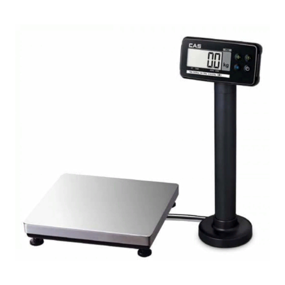
2. Specifications in Appearance 2-1. External Dimension (PDI) -
Page 11: Front Panel Descriptions
2-2. Front Panel Descriptions. (1) Main Display (Weight Display) A. Displaying the value of gross or net weight. B. Displaying error messages for any abnormal motion or weigh setup error/ C. Displaying the status value for the Set Mode and weight setup mode. (2) Status Display (Lamp) LED Lamp Descriptions... -
Page 12: Rear Panel Descriptions
2-3. Rear Panel Descriptions... - Page 13 SEALING Use it to set the weight (calibration). (CAL S/W) POWER * Use it for the power supply. LOAD CELL A port to connect load cell. RS-232C Serial Com 1 (connect PC or printer)
-
Page 14: How To Install
3. How to Install 3-1. How to Connect Load Cell Connect the load cell connector to the load cell port on the back of the indicator. * How to connect the load cell to the connector. Pin Function Number EXC+ SEN+ EXC- SEN-... -
Page 15: Weight Setup Mode
4. Weight Setup (Calibration) Mode What is the weight setup? It refers to the calibration to set the displayed value to the actual weight in displaying weights. How to Access to the Weight Setup Mode Turn on the power supply to access to the weight setup mode while pressing Cal S/W after removing the sealing. - Page 16 CAL 1 (CAL 1 automatically starts.) Function: Setting Maximum Value Range of set value: 1 ~ 99,999 Used key Display Descriptions :Save and C= 10000 Max. value = 10000kg next Menu navigation : Set value change Max. value = 10kg : Changing places Note 1.
- Page 17 CAL 3 CAL 3-1 Function: Setting Multi Calibration Step Range of set value: 1 ~ 5 Used key Display Descriptions Setting multi calibration for step 1 STEP- 1 (CAL3-3 and CAL 3-4 are carried out once) :Save and Setting multi calibration for step 3 next Menu navigation STEP- 3 (CAL3-3 and CAL 3-4 are carried out three...
- Page 18 CAL 3-2 Function: Zero Calibration Used key Display Descriptions UnLoAd Empty the load tray and press the setup key. The current weight value is displayed. 1234 Confirm 'Stable' and press the setup key. : Zeroing - - - Zeroing in progress... Note 1.
- Page 19 CAL 3-4 Function: Weight Calibration) Used key Display Descriptions Load the weight set in CAL3-3 and press the LoAd setup key. The current weight value is displayed. 12345 Confirm 'Stable' and press the setup key. :Span adjustment - - - Span adjustment in progress...
- Page 20 CAL 8 Function: Zero adjustment - calibration when any zeroing error occurs. Used key Display Descriptions 2-CAL Empty the load tray and press the setup key. The current weight value is displayed. 1234 Confirm 'Stable' and press the setup key. :Zero adjustment - - - Zero adjustment in progress...
- Page 21 CAL 10 CAL 10-1 Function: Setting Dual Range Range of set value: 0 ~ 1 Used key Display Descriptions DUAL- 0 Dual range function is not used. :Save and next Menu navigation DUAL- 1 Dual range function is used. : Set value change Note 1.
-
Page 22: Set Mode
5. Set Mode 5-1. How to Enter the Set Mode Turn on the power while pressing key at the indicator front to start the Set Mode. After finishing the setup in the Set Mode, press key for a long time (turn off the power) and turn on the power again. -
Page 23: Set Menu Descriptions (F00 ~ F99)
5-3. Set Menu Descriptions (F03 ~ F99) General Function (00) Auto Power Off (10) A/D Converting Speed (10) Digital Filter (00) Vibration Filter (02) Motion Detection Condition (02) Automatic Zero Tracking Compensation (00) Weight Backup (10) Set Zero Range (01) Set ZERO, TARE Keys Availability (01) Set "*"... - Page 24 RS-232 Serial Communication Function (00) Device ID (00) Parity Bit (04) COM1 Baud Rate (00) COM1 Usage (00) COM1 Output Format (00) COM1 - Output Mode (04) COM2 Baud Rate (01) COM2 Usage (00) COM2 Output Format (00) COM2 - Output Mode (01) Set ECR Type Print Function...
-
Page 25: General Function
5-3-1. General Function Function Auto Power OFF Display Meaning Setting range Not used. F03. 00 (00 ~ 30) F03. 10 Automatic power off after 10 minutes in the waiting mode. F03. 30 Automatic power off after 30 minutes in the waiting mode. Note 1. - Page 26 Function Setting Automatic Zero Tracking Compensation Display Meaning F08. 0 Automatic zero function is not used. Setting range F08. 1 If it changes slowly to 0.5 divisions or less, it is compensated. (0 ~ 9) If it changes slowly to 1.0 divisions or less, it is compensated. F08.
- Page 27 Function Weight Backup Function Display Meaning Setting range Disuse Print. F17. 0 (0, 1) F17. 1 Use Print. Function Set the initial zero range Display Meaning Setting range F21. 02 Set the initial zero up to 2% of the maximum weight (02~10) Set the initial zero up to 10% of the maximum weight F21.
-
Page 28: Rs-232 (Serial Communication) Function
Connect to a computer or auxiliary display * If F29: 0 and F33 : 0, "ERR-Set" is displayed with no print. Function Set COM1 - Output Format Display Meaning Setting range 22 bytes for CAS (0 ~ 2) 10 bytes for CAS 18 bytes for AND... - Page 29 Function Set COM1 - Output Mode Display Meaning No data out F31 0 F31 1 Transmission for both the stable and instable time (stream mode) Setting range F31 2 One time transmission after the weight is stabilized. (0 ~ 4) Transmission only if data is requested.
- Page 30 Serial Communication COM2 Function (USB Option) Function Set COM2 Baud Rate Display Meaning F32 0 600 bps F32 1 1200 bps F32 2 2400 bps F32 3 4800 bps Setting range (0 ~ 8) 9600 bps F32 4 F32 5 19200 bps F32 6 38400 bps...
- Page 31 MENU ECR-TYPE Data Format & Baud Rate Data Boadrate Display ECR-TYPE : Data Bit : Stop Bit : Parity Bit Most P.O.S, ECRs and Some TEC P.O.S System B:9600, D:8, S:1, P:NONE SHARP ER-Axxx, ER-A450T, New SANYO ECRs using RS-232 and B:9600, D:8, S:1, P:NONE TOLEDO 3213 etc.
-
Page 32: Print Function
5-3-3. Print Function Function Set Line Feed Display Meaning Setting range 1 Line feed F43 1 (0 ~ 9) F43 9 9 Line feed 【 Print Format 】 No.0001 Gross : 0.999 kg Tare : 0.000 kg 0.999 kg No.0002 Gross : 0.999 kg Tare :... -
Page 33: Test Mode
Note 1. To set values to the same as the factory default for the indicator, press the setup key after setting F99 to 1. 6. Test Mode 6-1. How to Enter the Test Mode Test mode starts when the power is turned on while pressing key in the front of the indicator. - Page 34 Test 2 Function: Display Screen Test Used key Display Descriptions An LCD lamp is on. : Test / Move to next menu Test 3 Function: Load cell test and A/D conversion test Used key Display Descriptions The internal value for the current XXXXXX weight value is displayed.
-
Page 35: Weighing Mode
7. Weighing Mode 7-1. Zeroing Function (used when the zero point changes) ■ Range of zero point: within a range set in F13 Zero chanced. Press Zero Key to set the zero lamp on and 0. 7-2. Tare Function (used for weighing with a container) - LED ■... -
Page 36: Rs-232C Interface In Detail
RS-232C port of CI-200 Serial port of the computer 2. RS-232 Communication Protocol 8-2-1. 22 Bytes for CAS (1) Data bit: 8, Stop bit: 1, Parity bit: none (2) Code: ASCII (3) Set the time to send data to the computer in the Set Mode. -
Page 37: Bytes For Cas
Stable Hold Printer Tare Zero Point Weight 8-2-2. 10 Bytes for CAS (1) Data bit: 8, Stop bit: 1, Parity bit: none (2) Code: ASCII (3) Transmission data format: (10 bytes) Data (8 bytes) 8-2-3. 18 Bytes for AND (1) Data bit: 7, Stop bit: 1, Parity bit: odd number / even number... -
Page 38: Error Message
9. Error Message 9-1. Error Message from the Weight Setup Mode Error Cause Solution Lower the resolution. The resolution was set in excess of As the resolution = maximum tolerance / value of one division, Err 21 adjust the resolution to 1/30,000 or less by correcting either the the tolerance 1/30,000. -
Page 39: Error Message From The Weighing Mode
9-2. Error Message from the Weighing Mode Error Cause Solution The initialization of the scale cannot be done Turn on the power after placing the scale at a flat Err 01 because of the shaking weight. place with no vibration. Either the connection of load cell is wrong or Check the connection between the load tray and the there is abnormality in the A/D conversion... - Page 40 Descriptions on Abbreviation on the Display Abbreviation Descriptions Abbreviation Descriptions "LOCK" Key Lock "UnLoad" Unload the load tray "PASS" Enter Password "LoAd" Load a weight "Discord" Re-enter Password "Good" Successful Execution ""CAL Weight Set Mode "SyS" System Mode "SET" Set Mode "PCS"...
- Page 41 MEMO...
- Page 42 MEMO...
- Page 43 MEMO...
Need help?
Do you have a question about the PDI Series and is the answer not in the manual?
Questions and answers