Subscribe to Our Youtube Channel
Summary of Contents for CAS PB Series
- Page 1 Service Manual – PB Series REV NO PB Series Service Manual LAST Rev. NO : LAST Rev. Date : 2009. 06. 10...
-
Page 2: Table Of Contents
Service Manual – PB Series REV NO Table of Contents 1 . P r o p e r O p e r a t i o n / I n t r o d u c t i o n ........................3 1 . -
Page 3: Proper Operation / Introduction
1. Proper Operation / Introduction 1.1. Preface Thank you for purchasing of our CAS scale. This scale has been designed with CAS reliability, under rigid quality control and with outstanding performance. WE hope that your departments enjoy with high quality of CAS product. -
Page 4: Classification
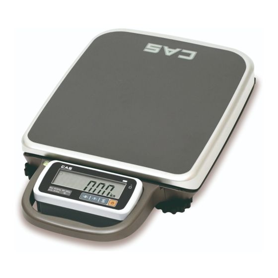
Service Manual – PB Series REV NO 2. Classification 2.1. Overall View 2.2. Display Pad (Key Pad) 2.2.1. PB(Basic) -
Page 5: Getting Started
Service Manual – PB Series REV NO Function ZERO (-O-) To set zero point [Set] To do [SET] key in the SETUP mode. TARE To input or cancel the tare (the weight of container). HOLD To make the weight of item stable. This weight is average value. -
Page 6: Calibration Mode
Service Manual – PB Series REV NO 4. Calibration Mode 4.1. General Calibration P r e s s i n g a n d h o l d i n g c a l i b r a t i o n s w i t c h p r e s s [ P O W E R ] k e y t o g o t o c a l i b r a t i o n m o d e . -
Page 7: C4 Setting
Service Manual – PB Series REV NO 4.1.1. C4 Setting 4.1.1.1. C4-1 Setting BIT 6~7 Initial Zero range Disable BIT5 Last digit enable Enable 3 % key zero percent ± BIT4 Key zero percent 2 % key zero percent ±... -
Page 8: Span Calibration Setting (C-3)
Service Manual – PB Series REV NO 4.1.2. SPAN Calibration Setting (C-3) “ ” ( 1 ) P r e s s i n g a n d h o l d i n g C a l i b r a t i o n S w i t c h p r e s s [ P O W E R ] k e y . -
Page 9: Percent Calibration (C-7)
Service Manual – PB Series REV NO (8) Press [TARE] key, and then “MCAPA“ message blinks.“0005” will be shown. The first digit,”0” will blink. It means a mid-capability is “05 (calibration unit, kg or lb)” (9) Input a capability by using [ZERO] key. -
Page 10: B A T T E R Y C A L I B R A T I O N
Service Manual – PB Series REV NO 4.1.7. Battery Calibration (C-8) (1) Pressing and holding “Calibration Switch” press [POWER] key. After “CAL” message blinks three times and shows the version of scale, it displays “CAL 1” message. (2) Press [ZERO] to display “CAL-8”. -
Page 11: E R R O R M E S S A G
The "Err 1" occurs when a current zero "Err 1" point has shifted from the last span Please call your CAS dealer. calibration. The "Err 2" is not a real error. Only it "Err 2" prompts return CAL switch to the Please call your CAS dealer. -
Page 12: U P D A T
Service Manual – PB Series REV NO 6.2. Serial Interface(RS-232C) 7. Update 7.1. ROM Download Method (1) Connect a RS-232C Cable, between the scale and PC and then excute a O/M Downloader program. - Page 13 Service Manual – PB Series REV NO (2) Check a ‘Communication port’ and click the ‘Init. Erase Command’. And then Click the ‘Start Download’, Communication port will be “Ready” status. ‘ ’ P u s h a O p e n R O M F i l e...
- Page 14 Service Manual – PB Series REV NO (4) If ‘ ’ c l i c k t h e S t a r t D o w n l o a d h o l d i n g a p o w e r O N / O F F k e y , Y o u w i l l s e e R O M D o w n l o a d i n g...
-
Page 15: E X P L O D E D V I E W S & P A R T S L I S
Service Manual – PB Series REV NO 8. Exploded Views & Parts List 8.1. Exploded View 8.1.1. Display Ass’y... -
Page 16: Scale Ass'y
Service Manual – PB Series REV NO 8.1.2. Scale Ass’y... - Page 17 Service Manual – PB Series REV NO 8.2. Loadcell Ass’y...
- Page 18 Service Manual – PB Series REV NO 8.3. Main PCB Ass’y (Top) 8.4. Main PCB Ass’y (Bottom)
- Page 19 Service Manual – PB Series REV NO 8.4.1. Main PCB(Part List)
-
Page 20: R E V I S I O
Service Manual – PB Series REV NO 8.4.1. PCB-Option (Part List) 9.Revision C A U S E D A T E A P P R O V A L P C B A r t w o r k , P a r t L i s t , C a l i b r a t i o n 2 0 0 9 .


Need help?
Do you have a question about the PB Series and is the answer not in the manual?
Questions and answers