Table of Contents
Advertisement
Quick Links
SHERWOOD INDUSTRIES IS AN ENVIRONMENTALLY RESPONSIBLE COMPANY. THIS MANUAL IS PRINTED ON RECYCLED PAPER.
PLEASE KEEP THESE INSTRUCTIONS FOR FUTURE REFERENCE.
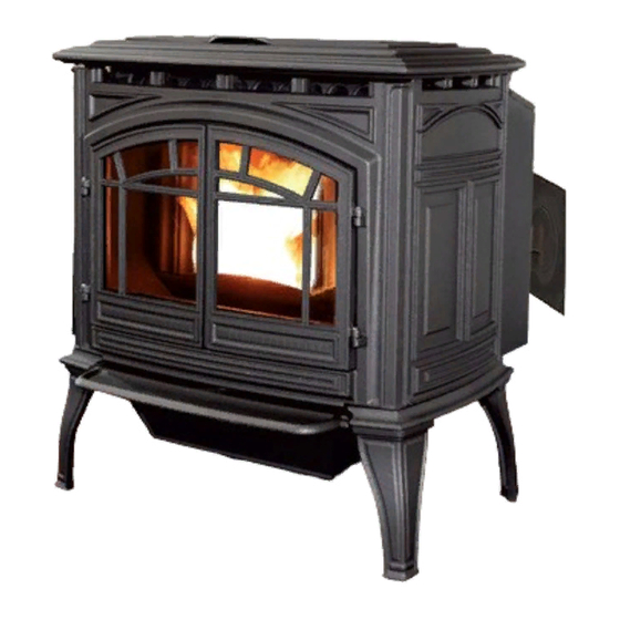
PELLET STOVE
M-55C-FS
TECHNICAL MANUAL
PLEASE READ THIS ENTIRE MANUAL BEFORE INSTALLATION
AND USE OF THIS PELLET-BURNING ROOM HEATER. FAILURE
TO FOLLOW THESE INSTRUCTIONS COULD RESULT IN
PROPERTY DAMAGE, BODILY INJURY OR EvEN DEATH.
Contact your building or fire officials about restrictions and installation
inspection requirements in your area.
50-2101
Advertisement
Table of Contents

Related Manuals for Enviro M-55C-FS


Summary of Contents for Enviro M-55C-FS
- Page 1 SHERWOOD INDUSTRIES IS AN ENVIRONMENTALLY RESPONSIBLE COMPANY. THIS MANUAL IS PRINTED ON RECYCLED PAPER. PLEASE KEEP THESE INSTRUCTIONS FOR FUTURE REFERENCE. PELLET STOVE M-55C-FS TECHNICAL MANUAL PLEASE READ THIS ENTIRE MANUAL BEFORE INSTALLATION AND USE OF THIS PELLET-BURNING ROOM HEATER. FAILURE TO FOLLOW THESE INSTRUCTIONS COULD RESULT IN PROPERTY DAMAGE, BODILY INJURY OR EvEN DEATH.
-
Page 2: Table Of Contents
Table of Contents Safety Warnings & Recommendations....................3 Specifications..........................5 Rating Label & Location......................5 Dimensions..........................6 Specifications...........................6 Installation.............................7 Deciding Where to Locate your Pellet Appliance................7 Removing Pellet Stove From Pallet.....................7 Clearances to Combustibles.......................8 Pedestal Base Adjustment......................8 Thermostat Installation......................8 Vent Termination Requirements....................9 Outside Fresh-Air Connection....................10 Exhaust And Fresh Air Intake Locations..................10 Mobile Home Installation......................11 Corner Through Wall Installation....................11... -
Page 3: Safety Warnings & Recommendations
To prevent the possibility of a fire, ensure that the appliance is properly installed by adhering to the installation instructions. An Enviro dealer will be happy to assist you in obtaining information with regards to your local building codes and installation restrictions. - Page 4 If this power cord should become damaged, a replacement power cord must be purchased from the manufacturer or a qualified Enviro dealer. Be careful that the electrical cord is not trapped under the appliance and that it is clear of any hot surfaces or sharp edges. This unit’s maximum power requirement is 504 watts.
-
Page 5: Specifications
Specifications & l ating abel ocation The rating label is located on the inside of the rear hopper access cover. -
Page 6: Dimensions
(703mm) " (819mm) " 17" (724mm) (431mm) Figure 2: Dimensions of M-55C-FS. pecificationS Input rating when using: Wood Pellets/Corn - 55,000BTU (16.1KW•hr) & Wheat/Barley - 53,000BTU (15.5KW•hr). Table 1: M-55C-FS Specifications. Description Fuel type Residential Pellet Heater 6mm (¼”) dia. Pellets - wood, corn, wheat, & barley*... -
Page 7: Installation
Installation eciding here to ocate your ellet ppliance 1. Do not install the stove in a bedroom or room where people sleep in. 2. Locate the stove in a large and open room that is centrally located in the house. This will optimize heat circulation. -
Page 8: Clearances To Combustibles
The unit must be installed with a minimum of 6” (152 mm) of floor protection in front of and to the sides of the door opening. Figure 4: M-55C-FS Clearance to Combustibles. eveling djuStment The leveling legs should be adjusted for the unit to to sit level and not rock if installed on uneven flooring. -
Page 9: Vent Termination Requirements
Installation ermination equirementS IT IS RECOMMENDED THAT YOUR PELLET STOVE BE INSTALLED BY AN AUTHORIZED DEALER/INSTALLER. Table 2: Use in conjunction with Figure 6 for allowable exterior vent termination locations. Letter Minimum Clearance Description 24 in (61 cm) Above grass, top of plants, wood, or any other combustible materials. 48 in (122 cm) Beside/below any door or window that may be opened. -
Page 10: Outside Fresh-Air Connection
FRESH AIR INTAKE. Base of unit to center of intake 12” (305 mm) " Center of unit to center of intake (392mm) ” (126 mm) 12" (305mm) " " " " (162mm) (200mm) (236mm) (126mm) Figure 8: M-55C-FS Inlet and Outlet Location. -
Page 11: Mobile Home Installation
Installation obile nStallation ● Secure the heater to the floor using the four (4) holes in the pedestal. ● Ensure the unit is electrically grounded to the chassis of your home (permanently). ● Do not install in a room people sleep in. -
Page 12: Horizontal Exhaust Through Wall Installation
Installation orizontal xhauSt hrough nStallation vent installation: install vent at clearances specified by the vent manufacturer. A chimney connector shall not pass through an attic or roof space, closet or similar concealed spaces, or a floor, or ceiling. Where passage through a wall or partition of combustible construction is desired, the installation must conform to CAN/CSA-B365 Installation Code for Solid-Fuel-Burning Appliances and Equipment and with all local regulations, including those referring to regional and national. - Page 13 Installation 8. The pipe must extend at least 12” (30 cm) away from the building. If necessary, bring another length of pipe to the outside of the home to connect to the first section. Do not forget to place high temperature silicone around the pipe that passes through the thimble if required by vent manufacturer.
-
Page 14: Recommended - Through Wall With Vertical Rise And Horizontal Termination Installation
Installation recommended - t hrough ertical iSe and orizontal ermination nStallation Termination cap 90°elbow Wall framing A 45° down elbow with a screen may be used in Vertical section place of the termination cap (or stainless steel of vent pipe termination hood). -
Page 15: Outside Vertical Installations
Installation utSide ertical nStallationS To accomplish an outside vertical pipe installation, follow the “h ” OrizOntAl xhAust hrOugh nstAllAtiOns section and then finish it by performing the following (refer to Figure 15). 1. Install a tee with clean out on the outside of the house. 2. -
Page 16: Inside Vertical Installations
Installation nSide ertical nStallationS 1. Place the unit on the hearth pad if a hearth pad is to be used (or on solid material if installed on a carpeted surface) and space the unit in a manner so when the pellet vent is installed vertically, it will meet the minimum clearance from a combustible wall stated by the vent manufacturer. -
Page 17: Hearth Mount Installation
Installation earth ount nStallation Damper Removed or Fastened Open Mantel Minimum (8") 200mm from top of stove Clean-out tee Min (6") 150mm Fresh-air intake should com from chimney. If holes already exist fresh-air intake Floor can be taken through back Protection of the fireplace or through the ash dump. -
Page 18: Slider/Damper Set-Up
Installation lider amper This is used to regulate the airflow through the pellet stove. Convection Slider Removable Plate Damper & Exhaust Sensor location Slider Damper Set Screw with " Hex Head Combustion Figure 20: Efficient Flame. Blower Note: The side panel, &... -
Page 19: Troubleshooting
Troubleshooting DO NOT: ● Service the stove with wet hands. The stove is an electrical appliance, which may pose a shock hazard if handled improperly. Only qualified technicians should deal with possible internal electrical failures. ● Do not remove from the firebox any screws without penetrating oil lubrication. WHAT TO DO IF: 1. - Page 20 Troubleshooting • Exhaust Temperature Sensor failure. Bypass sensor located on Exhaust Blower, if stove now operates properly, the unit may require cleaning or a new sensor. Contact your local dealer for service. • Check the agitator to make sure it is turning properly 3.
- Page 21 Troubleshooting 7. The convection blower will not function normally. • Check the line fuse to see if it has blown. • Clean all grill openings at the back and below unit . • Check the Voltage across the blower wires, It should adjust with the heat output settings. If not contact your local dealer for service.
-
Page 22: Wiring Diagram
Wiring Diagram Black Brown 2µF Capacitor Black Exhaust Blue Combustion Temperature Brown Blower Blue Blue Sensor Black White 120V Ground Air Pump White Plug Green Ground Ignitor White Ground Thermostat White Agitator Blue/Yellow Black Motor White Auger Yellow Yellow Motor Purple Brown Blue... -
Page 23: Parts List
Parts List ITEM # DESCRIPTION PART # AUGER WITH PADDLES 50-1161 VACUUM SWITCH LOW PRESSURE 50-1390 AUGER STOPS (CLEAR RUBBER) 50-1559 AUGER PLATE AND BUSHING (ASSEMBLY) 50-1658 BURN POT 50-1692 STAINLESS STEEL CAST AGITATOR W COUPLER 50-1697 AGITATOR DRIVE SHAFT W/ SPROCKET 50-1698 MOTOR DRIVE SPROCKET 50-1700... - Page 24 Parts List ITEM # DESCRIPTION PART # M55C-FS CAST FRONT WITH DOORS - BEACH 50-2120 M55C-FS CAST FRONT WITH DOORS - CHESTNUT 50-2130 CONTROL PANEL WITH DECAL 50-2108 M55C-FS DAUGHTER BOARD 50-2109 M55C-FS MOTHER BOARD 50-2110 M55C-FS CAST SIDE LEFT 50-2111 M55C-FS CAST SIDE LEFT - BEACH 50-2123...
-
Page 25: Parts Diagram - Components
Parts Diagram - Components... -
Page 26: Parts Diagram - Cast
Parts Diagram - CAST... -
Page 27: Warranty
Industries, our commitment to the highest level of quality and customer service is the most important thing we do. Each Enviro stove is built on a tradition of using only the finest materials and is backed by our Exclusive Lifetime Limited Warranty to the original purchaser. With Enviro, you’re not just buying a stove, you’re buying a company with years of unequalled performance and quality. - Page 28 Limited Warranty on this stove. If unsure as to the extent of this Limited Warranty, contact your authorized Enviro dealer before installation. 10. Sherwood Industries Ltd. will not be responsible for inadequate performance caused by environmental conditions.
- Page 29 If the stove is used for commercial purposes, it is excluded from the Limited Warranty. 23. No dealer, distributor, or similar person has the authority to represent or warrant Enviro products beyond the terms contained within the Limited Warranty. Sherwood Industries Ltd. assumes no liability for such warranties or representations.
-
Page 30: Installation Data Sheet
SERIAL NUMBER:___________________________ _________________________________________ DATE OF PURCHASE: _____________ (dd/mm/yyyy) DATE OF INSTALLATION:___________ ADDRESS: (dd/mm/yyyy) MAGNEHELIC AT INSTALL:___________________ _________________________________________ INSTALLER’S SIGNATURE: _________________________________________ _________________________________________ _________________________________________ PHONE:___________________________________ MANUFACTURED BY: SHERWOOD INDUSTRIES LTD. 6782 OLDFIELD RD. SAANICHTON, BC, CANADA V8M 2A3 www.enviro.com July 11, 2011 C-12003...
Need help?
Do you have a question about the M-55C-FS and is the answer not in the manual?
Questions and answers