Enviro Maxx-1 Installation Manual
Heat distribution kit
Hide thumbs
Also See for Maxx-1:
- Owner's manual (16 pages) ,
- Technical manual (30 pages) ,
- Manual (12 pages)
Advertisement
Quick Links
PLEASE SAVE THESE INSTRUCTIONS FOR FUTURE REFERENCE.
Enviro Maxx-1
Heat Distribution Kit
INSTALLATION MANUAL
PLEASE READ THIS ENTIRE MANUAL BEFORE INSTALLATION AND
USE OF THIS PELLET-BURNING ROOM HEATER. FAILURE TO FOLLOW
THESE INSTRUCTIONS COULD RESULT IN PROPERTY DAMAGE,
BODILY INJURY OR EVEN DEATH.
CONTACT YOUR LOCAL BUILDING OR FIRE OFFICIALS ABOUT
RESTRICTIONS AND INSTALLATION INSPECTION REQUIREMENTS IN
YOUR AREA.
2
Advertisement

Related Manuals for Enviro Maxx-1


Summary of Contents for Enviro Maxx-1
- Page 1 PLEASE SAVE THESE INSTRUCTIONS FOR FUTURE REFERENCE. Enviro Maxx-1 Heat Distribution Kit INSTALLATION MANUAL PLEASE READ THIS ENTIRE MANUAL BEFORE INSTALLATION AND USE OF THIS PELLET-BURNING ROOM HEATER. FAILURE TO FOLLOW THESE INSTRUCTIONS COULD RESULT IN PROPERTY DAMAGE, BODILY INJURY OR EVEN DEATH.
- Page 2 Parts List............................11 SAFETY WARNINGS & RECOMMENDATIONS Please read this entire Technical Manual before installing or operating your Enviro Pellet Stove with Heat Distribution Kit. Failure to follow these instructions may result in property damage, bodily injury or even death. Any unauthorized modifi cation of the stove or Heat Distribution Kit is prohibited. All national and local regulations must be followed when operating this pellet stove with Heat Distribution Kit option.
-
Page 3: Installation
Installation Instructions 50-2891 HEAT DISTRIBUTION KIT HARDWARE ITEM NO. DESCRIPTION QTY. #8 X 3/8" Sheet Metal Screw #8 X 3/8" T-20 Screw #8 X 1/2" Self Drilling Screw Electrical Wire Tie 6in with Hole 1. Remove combustion adjustment slider knob as well as lock collar on left side of unit. - Page 4 3. After loosening the screws holding on the cabinet sides, slide sides toward front of stove to remove. 4. Remove Front Grill assembly, four T-20 screws. Figure 3: Cabinet sides removal. Figure 4: Original front gill removal. 5. Remove Front Top assembly, four screws. 6.
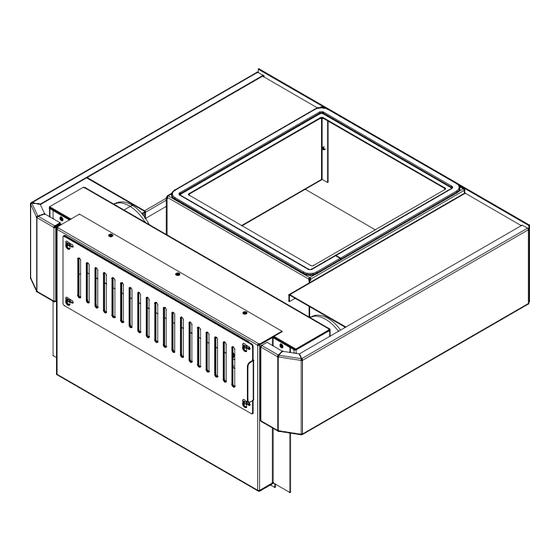
- Page 5 7. Remove old lid gasket, a utility knife may be required. 8. Install Front HDK assembly. Assembly should slide downward into place and is secured using two #8 sheet metal screws. Screws thread into top holes where front original grill was mounted. Figure 7: Original lid gasket removal.
- Page 6 11. Attach the Duct Shields using four provided #8 sheet metal screws. 12. You should now wire the kit. Remove Front Grill and Vent to access Sensor bracket and wires, refer to page 10 for wiring instructions. Figure 12: Accessing sensor bracket. Figure 11: Install of duct shields.
- Page 7 14. Attach Cab Extensions to back plate using two #8 sheet metal screws on each side. Mount one hinge using #8 T-20 screws. Figure 15: Cabinet side extension install. Figure 16: Hinge & Cabinet side extension fastener install. 15. Re-install other hinge and lid. Hinge mounting holes have been shifted vertically up on the back plate.
- Page 8 Ducting Specifications Ducting coming from Heat Distribution Kit must have a one inch clearance to any combustible materials when passing through a wall or fl oor. Duct runs should be less than 20ft for best results. Wall 1.00" Air Gap Figure 18: Duct install clearance.
-
Page 9: Wiring
Wiring *DISCONNECT POWER FROM UNIT BEFORE WIRING* a. With the Front Grill and Vent removed feed the wires inside the front assembly through the opening on the right side shown in Figure 20. Use the supplied screw mount wire ties to secure wires at circled screws. b. -
Page 10: Wiring Diagram
Wiring Diagram... -
Page 11: Parts List
PARTS LIST Part No. Description Replacement No. HDK Back Assembly HDK Front Assembly Lid Gasket EF-208 Cabinet Side Extention Duct Shield Slider Grill 50-2887 Grill 50-2886 Sensor Assembly High Limit Sensor (220F) EC-002 Fan Sensor (120F) EC-001 Control Sensor (175F) 50-2888 Sensor Detail A... - Page 12 MANUFACTURED BY: SHERWOOD INDUSTRIES LTD. 6782 OLDFIELD RD. SAANICHTON, BC, CANADA V8M 2A3 www.enviro.com Oct. 7, 2013 C-14262...
Need help?
Do you have a question about the Maxx-1 and is the answer not in the manual?
Questions and answers