Table of Contents
Advertisement
Advertisement
Table of Contents

Related Manuals for Ask Proxima E1655U


Summary of Contents for Ask Proxima E1655U
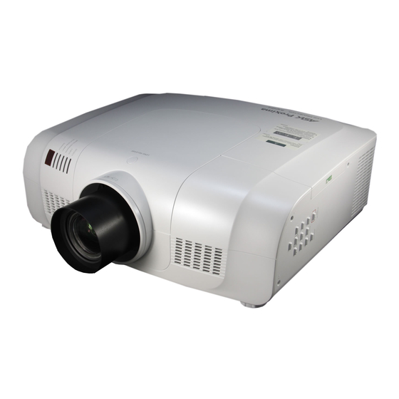
- Page 1 Multimedia Projector E1655U MODEL Owner’s Manual P/N:4100534500...
- Page 2 Property Statement The copyright of this manual belongs to Shenzhen ASK Proxima Digital Video Technology Co., Ltd. and is protected by Copyright Law of the People’s Republic of China and related laws. No unit or individual is allowed to extract, copy, translate, or issue any part of the publication in any form or by any means without the prior permission of the copyright owner.
-
Page 3: Table Of Contents
Table of Contents Table of Contents ..... .2 Computer Input mputer Input ..... .27 To the Owner. -
Page 4: To The Owner
To the owner Please read this manual completely before installing and Safety precautions operating the projector. The projector provides many convenient features and Caution: The projector must be grounded. ● functions. Proper operation may enable you to fully utilize the features and keep it in good condition. Otherwise, it Do not expose the projector to raindrops or high ●... - Page 5 Safety guide All the safety and operating instructions should be read Never push objects of any kind into this projector before the product is operated. through cabinet slots as they may touch dangerous voltage points or short out parts that could result in a Read all of the instructions given here and retain them fire or electric shock.
-
Page 6: Safety Guide
Safety guide Air circulation Installing the projector in proper directions Openings in the cabinet are provided for ventilation. To Install the projector properly for normal operation. ensure reliable operation of the product and to protect it Improper installation may reduce the lamp lifetime and from overheating, these openings must not be blocked or cause a fire hazard. -
Page 7: Moving The Projector
Safety guide Moving the projector Caution on lens protector Before use, remove the lens protector. To move the projector, press and hold the Shift or lens key more than 5 seconds to center the lens back. Then, install the protector to protect the lens. Lens protector When moving the projector, retract the adjustable feet to prevent damage to the lens and cabinet. -
Page 8: Part Names And Functions
Part names and functions ⑧ ② ① ③ Front (1) Lens release button (2) Indicator (3) Lamp cover (4) Speaker (5) Lens cap (6) Projector lens ⑥ (7) Decorative cover (8) Remote receiver (Front & top) ⑩ (9) Side control panel ⑨... -
Page 9: Rear Terminal
Part names and functions Rear terminal (1) Network port (7) S-VIDEO Used to connect the S-video output of video Used to connect the network cable. equipment. (8) Composite (video) input jacks (2) COMPUTER IN2/MONITOR OUT Connect the composite signals to this - Used to connect the computer output. -
Page 10: Side Control And Indicators
Part names and functions Side control and indicators Side control Indicators (Top panel) Point (VOLUME +/–) buttons SELECT button ▲▼◄► –Enter full menu from shortcut. – Select an item or adjust the value in the –Execute the selected item. On-Screen Menu. –Expand or compress the image in the Digital zoom –... -
Page 11: Remote Control
Part names and functions Remote control ① ON-STANDBY button ① Turn the projector on or off. button ② HDMI/DVI /DVI ② Select HDMI or DVI input source. ③ ⑤ ③ COMPUTER button ④ Select VGA1 or VGA2 input source. ⑥ ⑨... - Page 12 Part names and functions Remote control ⑯ LENS button Select the lens shift mode. ① ZOOM button ⑰ Zoom in/out images. /DVI FOCUS button ② ⑱ ③ Adjust the focus. ⑤ ④ LAMP ⑲ button ⑥ ⑨ Select the lamp mode. ⑧...
-
Page 13: Remote Control Battery Installation
Part names and functions Remote control battery installation Open the battery Install new batteries into the Replace the compartment lid. compartment lid. compartment. For correct polarity (+ and –), be sure battery terminals are in contact with pins in the compartment. -
Page 14: Installation
Installation Positioning the projector Note √ The brightness in the room has a great influence on picture quality. It is recommended to limit the ambient lighting in order to get the best image. All measurements are approximate and may vary from the actual sizes. 18.187 m Diagonal 11.319 m... -
Page 15: Connecting To A Computer
Installation Connecting to computer (Digital and analog RGB) Cables used for connection ( =Cables are not supplied with the projector.) • • Serial crossover cable (F-F) * VGA cable (1) HDMI cable * BNC cable * • • Serial output Monitor input * Monitor output HDMI terminal... -
Page 16: Connecting To Video Equipment
Installation Connecting to video equipment Cables used for connection (*=Cables are not supplied with the projector.) • Video cable (RCA* 1 or RCA*3) * • BNC cable (BNC*1 or BNC*3) * • S-Video cable * • Scart-VGA cable * S-video output Composite Composite... -
Page 17: Connecting To Audio Equipment
Installation Connecting to audio equipment Cables used for connection (* =Cables are not supplied with the projector.) Audio cable * External audio equipment Audio output Audio output Audio input (R) (L) Audio cable Audio cable (Stereo) Audio cable (Stereo) Audio cable (Stereo) Audio IN Audio cable... -
Page 18: Connecting The Ac Power Cord
Installation Connecting to the AC power cord This projector uses nominal input voltages of 100–240 V AC and it automatically selects the correct input voltage. It is designed to work with a single-phase power system having a grounded neutral conductor. To re duce the risk of electrical shock, do not plug into any other type of power system. -
Page 19: Lens Installation
Installation Lens installation Follow the instructions below to install the lens upon replacing or using the provided lens. For the specification of projector lens, contact your dealer. Removing the lens Lens release button Shift the lens to the center with the lens shift function. -
Page 20: Basic Operation
Basic operation Turning on the projector Complete peripheral connections (with a computer, VCR, etc.) before turning on the projector. Connect the projector’s AC power cord into an AC outlet. The POWER indicator turns red. Open the lens cap. Press the ON/STAND-BY button on the top control or on the remote control. -
Page 21: Turning Off The Projector
Basic operation Turning off the projector Press the ON/STAND-BY button on the side control or on the remote control, and “Power off?” appears on the screen. Power off ? Press the ON/STAND-BY button again to turn off the projector. The POWER indicator starts to flash red, and the cooling fans keep running. -
Page 22: How To Operate The On-Screen Menu
Basic operation How to operate the on-screen menu Remote control The projector can be adjusted or set via the on-screen menu, including Shortcut menu and Full menu. General operations are available via the shortcut menu. Indicators A full menu features multiple structures. Each main menu can be divided into several levels of submenus, Select button and submenus are also divided into several levels of... -
Page 23: Full Menu Bar
Basic operation Full menu bar Main menu Sub menu Input ① HDMI ② Computer 1 ③ Computer 2 Input ④ Component S-video ⑤ Video 1 Video 2 ⑥ RGBHV ⑦ SCART System ⑧ Exit Move Next Next MENU SELECT ⑨ (1) PC adjust menu Used to adjust parameters, like Auto PC adj. -
Page 24: Zoom And Focus Adjustment
Basic operation Remote control Auto setup function Arrow keys ▲▼ This function is available just by pressing the Auto Setup button on the top control. The system then automatically performs various settings in the setup menu, including input Keystone source search, and auto computer adjustment. correcting button Auto setup... -
Page 25: Sound Adjustment
Basic operation Keystone ▲ Keystone ▼ If a projected picture has keystone distortion, correct the image ● The arrows are white when there is with the Keystone function. no correction. Press the KEYSTONE button on the top control or on the ●... -
Page 26: Remote Control Operation
Basic operation Remote control operation Using the remote control for some frequently used operations is advisable. Just pressing one of the buttons enables you to make the desired operation quickly without calling up the on-screen menu. Remote control /DVI HDM I/DVI Direct INPUT button Press the Computer/video/HDMI/ DVI/S-Video/RGBHV/ Computer... - Page 27 Basic operation BLANK button Blank Press the BLANK button to black out the image. To restore to normal, press the BLANK button again or press any other button. The screen changes each time you press the button as follows. Black out →Normal →Black out →Normal... “Blank”...
-
Page 28: Computer Input Mputer Input
Computer input Input source selection ( HDMI Computer 1 or Computer 2) Direct operation Press the INPUT button on the side control or the COMPUTER button on the remote control to select either Computer 1 or Computer 2 Computer Remote control Computer COMPUTER button Component... - Page 29 Computer input Full menu operation Input menu Press the F.MENU button to display the full screen menu. Use the buttons to select the input Input ▲▼ source icon and press the button or SELECT HDMI ► button. Computer 1 Computer 2 Press the buttons to select RGBHV, and Input...
-
Page 30: Computer System Selection
Computer input Computer system selection The projector automatically tunes to various types of computers with its function of Multi-scan system and Auto PC Adjustment. If a computer is selected as a signal source, the projector automatically detects the signal format and tunes to project proper images without any additional setting. -
Page 31: Auto Pc Adjustment
Computer input Auto PC adjustment Auto PC Adjustment function is provided to automatically adjust total dots, horizontal position, vertical position, Display area H , and Display area V to conform to your computer. PC adjust menu Full menu operation PC adjust Auto PC adj. -
Page 32: Manual Adjustment Via Pc
Computer input Manual adjustment via PC As some PCs adopt special signal formats, the multi-purpose scanner of the projector may not detect them. To match the special-format signals, the projector offers function of manual adjustment, with which users can adjust the parameters. provides 5 independent memory sections, where the manually adjusted parameters can be saved. -
Page 33: Selecting Image Mode
Computer input Selecting image mode Direct selection: Remote control Use the key Image on the remote control to select the image mode. Operation through F. Menu 1. Press F. Menu to display the F. Menu. Press ▲▼ to select the icon for Image select . Then press ► or press Select. -
Page 34: Adjusting Image
Computer input Adjusting image 1. Press F. Menu on the remote control to display the on-screen menu. Press ▲▼ to select the icon for image adjust . Image adjust menu Then press ► or press Select. Image adjust 2. Press ▲▼ to select the item to be adjusted, and then press Contrast Select. -
Page 35: Adjusting Screen Size
Computer input Screen Menu Adjusting screen size Screen Normal The size of the screen can be re-set to the value the user desires. True Full Custom 1. Press F. Menu on the remote control to display the Digital zoom + on-screen menu. -
Page 36: Video Input
AV Input Selecting input source (video, S-video, Component, SCART, HDMI) Direct selection Press the input key on the control panel at the side , or press Video, S-video, Component, SCART, HDMI on the remote control, to select Video, S-video, Component, SCART and HDMI HDMI/DVI Vide HDMI... -
Page 37: Selecting Av System
AV Input Selecting AV system 1. Press F. Menu on the remote control to display the on-screen menu. Press ▲▼ to select the AV System Menu (Video or S-video) icon for input source. Then press ► or press Select. Input HDMI 2. -
Page 38: Selecting Image Mode
AV Input Selecting image mode Direct selection: Remote control Use the key Image on the remote control to select the image mode. Menu selection 1. Press F. Menu to display the F. Menu. Press ▲ ▼ to select the icon for image select. Then press ►... -
Page 39: Adjusting Image
AV Input Adjusting image 1. Press F. Menu on the remote control to display the on-screen menu. Press ▲▼ to select the icon for Image adjust menu image adjust. Then press ► or press Select. 2. Press ▲▼ to select the item to be adjusted, and Image adjust then press Select. -
Page 40: Adjusting Screen Size
AV Input Adjusting screen size The size of the screen can be re-set to the value the user desires. 1.Press F. Menu on the remote control to display the screen menu. Press ▲▼ to select the screen. Then press ► or press Select. 2.Press ▲▼... -
Page 41: Setting
Setting Setting You can use the setting menu to configure the following functions. menu Setting 1. Press F. Menu on the remote control to display the Language English OSD setting on-screen menu. Press ▲ ▼ to select Setting. Auto setup Then press ►... - Page 42 Setting Auto setup This function enables Input search, and Auto PC adjustment NOTE: AUTO SETUP button on the top control or the by pressing the • Only the last selected input source can be AUTO SET button on the remote control.
- Page 43 Setting Display You can use this item to set whether the startup animation is displayed. On ......Show startup screen Off ......Show the input image instead of the on-start screen Logo (Logo and Logo PIN code lock settings) This function allows you to customize the screen logo with Logo select, Capture, Logo PIN code lock and Logo PIN code change functions.
- Page 44 Setting Logo PIN code lock Use the Point ▲▼ buttons to enter a number. Press the Point ► button to fix the number and move the red frame pointer to the next box. The number changes to “*”. If you fixed an incorrect number, use the Point ◄ button to move the pointer to the number you want to correct, and then enter the correct number.
- Page 45 Setting Ceiling This function is used to project the image from a ceiling- mounted projector. Off ..Disable this function. Auto ..The picuture will be top/bottom and left/right reversed automatically. On..The picture will be top/bottom and left/right Rear reversed. Rear When this function is set to On, the picture will be left/right reversed.
-
Page 46: Lamp Control
Setting Standby mode This function is available when operating the projector via network. Normal ..Supply the power to the network function even after turning off the projector. You can turn on/ off the projector via network, modify network environment, and receive an e-mail about projector status while the projector is powered off. - Page 47 Setting PIN code lock This function prevents the projector from being operated by unauthorized persons and provides the following setting options for security. Off .... Unlocked. On ... Enter the PIN code every time turning on the projector. Whenever you change the PIN code lock setting or the PIN code (the three-digit number), you are required to enter the PIN code.
- Page 48 Setting Cooling fast There are the following options in the cooling fans operation when the projector is turned off. ON ... Faster and louder-sound than the normal operation, but it takes less time to cool the projector down. OFF ... Normal operation. High land This projector provides Fan control function in the "Setting"...
-
Page 49: Information
Information Displaying input source The information menu is used to detect signal of projected image and running state Operation through menu Press ▲▼ to select the information. And the information menu will appear. You can then see the information displayed as follows: Menu Operation Press menu on the Top Control and then press SELECT button to display on screen menu. -
Page 50: Maintenance And Cleaning
Maintenance “Warning Temper” indicator The “Warning Temper” indicator tells in what protection state engaged. The user should check the “Warning Temper” indicator and power indicator to make sure they work. On-top control panel Projector is in OFF state, and “Warning Temper” indicator flashes red. When its internal temperature exceeds the normal value, will be automatically powered off to protect the parts. -
Page 51: Cleaning The Filter
Maintenance Cleaning the filter The filter prevents dust from accumulating on the surface of lens assembly. Should the filter become clogged with dust particles, it will reduce the cooling fan’s effectiveness and may result in internal heat buildup and adversely affect the life of the projector. If a Filer warning icon appears on the screen, you should clean the filter immediately. -
Page 52: Covering The Lens Properly
Maintenance Covering the lens properly If needs to be moved or won’t be used for extended period of time, you should cover the lens properly. Cleaning the lens Unplug the AC power cord before cleaning. Apply some non-abrasive cleaning agent exclusively designed for cameras onto a piece of clean cloth, and then use it to wipe the lens gently. -
Page 53: Replacing The Lamp
Maintenance Replacing the lamp When the service life of the projection lamp is over, the icon suggests that the lamp needed to be replaced will appear on the screen, and the indicator for the replacement will flash yellow. If so, you should immediately replace it with a new one of the same model. -
Page 54: Maintenance
Maintenance Changing the lamp model Purchasing new lamps Users can buy new lamps through the local distributor. Your purchase order should include the information below: :APU-L8 Lamp model ● LAMP HANDLING PRECAUTIONS This projector uses a high-pressure lamp which must be handled carefully and properly. Improper handling may result in accidents, injury, or create a fire hazard. -
Page 55: Appendix
Appendix Troubleshooting Before you contact the local distributor or repair center, you may check the items below once again. -Make sure you have properly connected to the peripheral equipment. -Make sure all equipment has been connected to AC power source and the power source is in ON state. -If it can’t project image output from a PC, please re-start the PC. - Page 56 Appendix No image -Check the connection between PC or video equipment -Check with the signal from PC is correct. If connected to certain laptops, the settings of their video adapters need to be changed. You can refer to the operating instructions of the PC for such modification.
- Page 57 Appendix Distorted image or no image -Check and adjust the PC menu or on-screen menu. The PIN code dialog box popes up in the -A PIN code is set for locking. startup process -Check the battery. Remote control doesn’t work -Make sure there is no obstacle remote control.
-
Page 58: Indicator And Projector State
Appendix Indicator and projector state Check the indicator to know about the state of projector. Indicator State of projector POWER WARNING LAMP FOCUS SHIFT (Green) (Green/red) (Red) (Yellow) (Blue) Is in power-off state (AC power cord not inserted). Is in standby state. Press ON/STNADBY to power on the projector. - Page 59 Appendix Compatible PCs Is compatible with all analog and digital signal formats under 160MHz of DCLK, whose resolution and correspondent field frequencies are listed below: Signal format Resolution Field frequency(HZ) Signal format Resolution Field frequency(HZ) 640x400 1152x900 1152x900 640x400 640x400 1280x1024 640x480 1280x1024...
-
Page 60: Rs232 Commands Spec
Appendix RS232 Commands SPEC 1. Connection 1.1 Port Setting Item Method Communication Method Asynchronous Communication Bits per seconds 19200 Data bits 8 bits Parity None Stop bits Flow control None 1.2 Wiring RS232 cross cable is applied Projector Control Port N.C. - Page 61 Appendix 2. Commands Case sensitive,each command end by[CR](Carriage Returns). Command Item Command Item POWER ON Component POWER OFF (Quick Power OFF) Video POWER OFF S-Video VGA1 HDMI VGA2 2.1 POWER ON Command “A00”[CR] (Hex: Ox41 0x30 0x30 0x0d) Details Power ON when projector is in standby mode [ACK][CR]...
- Page 62 Appendix 2.5 VGA 2 Command “A06”[CR] (Hex:Ox41 0x30 0x36 0x0d) Details Change the input to "Computer2". [ACK][CR] Return “ ?”[CR] 2.6 Component Command “A07”[CR] (Hex:Ox41 0x30 0x37 0x0d) Details Change the input to "Component". [ACK][CR] Return “ ?”[CR] 2.7 Video Command “A33”[CR] (Hex:Ox41 0x33 0x33 0x0d) Details Change the input to "Video".
-
Page 63: User Manual For Network Control
Appendix User manual for network control Function : this function is for PC’s to remote control projectors through LAN cable. Preparation: 1. Equipments: PC, projector, cables 2. Connection procedures: Connect the projector to routers or switches of the LAN by direct or cross cable. If it fails to connect PC and projector by parallel cable, please switch to cross cable as suggested. - Page 64 Appendix (4) Press SELECT, choose ON by ▲▼ (figure 4) Network Setting and Press SELECT again. DHCP IP Address Subnet Gateway (figure 3) cancel (figure 4) Network Setting DHCP IP Address (5) Select SET by ▲▼(figure 5) and then press Subnet SELECT.
-
Page 65: Configurations Of Terminals
Appendix Configuration of terminals OMPUTER IN 1/COMPUTER IN 2/MONITOR OUT (analog) Terminal: Analog RGB (D-sub 15-pin) (Input/output) ----- Green (Input/output) Grounding (field synchronizing) Grounding Blue (Input/output) DDC data ----- Horizontal synchronizing (compound sync.) input/output Grounding (line synchronizing) Vertical synchronizing Grounding (red) input/output Grounding (green) DDC clock... -
Page 66: Outer Dimensions
Appendix Outer dimensions Unit: mm Screw hole used when installed on the ceiling LCD PROJECTOR Screw:M6 Depth:10.0 193.4 176.9 534.5 3 0 0 1 5 0 Content of hazardous substances and elements Name of parts Hazardous substances and elements Cr6+ PBDE Plastic parts ○... -
Page 67: Optional Parts
Appendix Optional parts Listed below are optional parts. Users should provide distributors with such information as part name and model when they place the order. Ultra-long Wide-range Short-focus Telephoto tandard lens Type lens lens -focus lens lens Appearance Electric Zoom/Focus X1.6/Power Flred/Power X1.6/Power...
Need help?
Do you have a question about the E1655U and is the answer not in the manual?
Questions and answers