
Related Manuals for Avdel 73432-02000


Summary of Contents for Avdel 73432-02000
-
Page 1: Instruction Manual
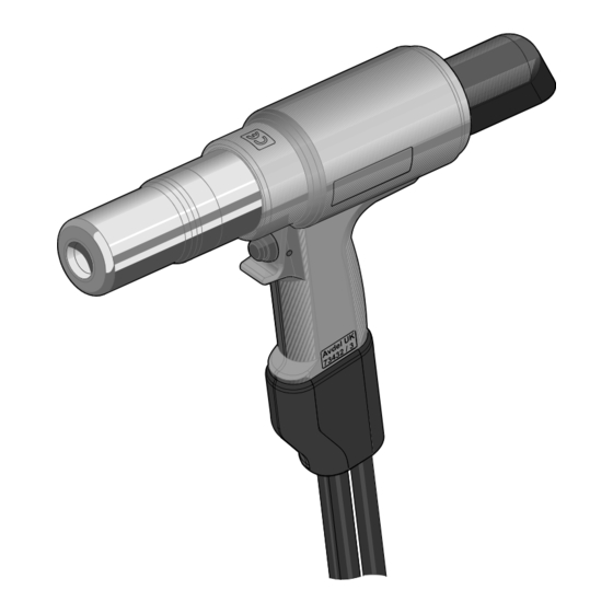
Instruction Manual Original Instruction AV™15 Installation Tool – 73432-02000 Hydro-Electric Power Tool... -
Page 2: Table Of Contents
IMPLIED WARRANTY AS TO QUALITY, FITNESS FOR PURPOSE, OR MERCHANTABILITY ARE HEREBY SPECIFICALLY DISCLAIMED AND EXCLUDED BY AVDEL. Avdel UK Limited policy is one of continuous product development and improvement and we reserve the right to change the specification of any product without prior notice. -
Page 3: Safety Instructions
This instruction manual must be read with particular attention to the following safety rules, by any person installing or operating this tool. Do not use outside the design intent. Do not use equipment with this tool/machine other than that recommended by Avdel ® UK Limited. - Page 4 Safety Instructions AVDEL ® RECOMMENDS THAT ONLY AVDEL ® /ENERPAC ® HYDRAULIC PUMP UNITS BE USED TO DRIVE INSTALLATION TOOLS, AS OTHER MAKES OF HYDRAULIC POWER UNITS MAY NOT OPERATE AT THE SAFE DESIGNED WORKING PRESSURES. ENSURE THAT THERE IS ADEQUATE CLEARANCE FOR THE TOOL OPERATOR'S HANDS BEFORE PROCEEDING.
-
Page 5: Specification
Industrial Environments. The placing tool and hydraulic pump unit may only be used in accordance with the operating instructions for placing ® Avdel fasteners. Refer to the table below for the list of applicable fasteners and associated nose equipment. -
Page 6: Placing Tool Dimensions
Specification Placing Tool Dimensions 134.5 46.5 All dimensions are shown in millimetres. Refer to the table on page 5 for the nose assembly dimensions ‘A’ and ‘B’. The tool is fitted with two Hydraulic Hoses and an electrical Control Cable, 0.6m in length. Additional hydraulic hose and cable extension lengths are available to order separately as required. -
Page 7: Putting Into Service
MANUAL CAREFULLY BEFORE PUTTING INTO SERVICE ® ® When both hoses and control cable are connected to the Avdel /Enerpac hydraulic pump unit, the pull and return cycles of the tool are controlled by depressing and releasing the trigger located in the handle. -
Page 8: Preparation For Use
Switch on the mains supply to the hydraulic pump unit. Wait 5 seconds for the pump unit to complete the boot sequence, before pressing the trigger switch. When all set the LCD screen on the pump unit will display ‘AVDEL’. ... -
Page 9: Operating Instructions
Putting Into Service Operating Instructions To Install an Avbolt ® Fastener Check work and remove excessive gap. (Gap is the space between components of the Joint. Gap is excessive if not enough pintail sticks through the collar for the nose assembly jaws to grab onto). ... -
Page 10: Servicing The Tool
Servicing the Tool IMPORTANT - READ SAFETY INSTRUCTIONS ON PAGE 3 AND 4. THE EMPLOYER IS RESPONSIBLE FOR ENSURING THAT TOOL MAINTENANCE INSTRUCTIONS ARE GIVEN TO THE APPROPRIATE PERSONNEL. THE OPERATOR SHOULD NOT BE INVOLVED IN MAINTENANCE OR REPAIR OF THE TOOL UNLESS PROPERLY TRAINED. -
Page 11: Dismantling Instructions
Servicing the Tool Use only Enerpac ® HF hydraulic oil – the use of any other oil may cause the placing tool and pump to malfunction and will render the placing tool warranty null and void. Hydraulic oil is available to order under the following part numbers. HYDRAULIC OIL PART NUMBER 07992-00081... - Page 12 Servicing the Tool Remove Rear Bearing Ring 29 and check the part for wear or damage. Discard if necessary. Remove the placing tool from the vice and empty the hydraulic oil from the rear of the tool. Remove the spare *Quick Coupler –...
- Page 13 Servicing the Tool Press the Front Bearing Ring 24 into the internal recess within the Front Seal Gland 15 and then install Rod Seal 25 behind the Front Bearing Ring. Install the Wiper Seal 22 in the front recess of the Front Seal Gland. Refer to the General Assembly to ensure the correct orientation of the Rod Seal and Wiper Seal.
- Page 14 Servicing the Tool Place the Rear Seal Gland 16 over the *Piston Bullet - Rear. Then push the Rear Seal Gland over the Piston 1 shaft and into the rear of the Body 2. Push the Rear Seal Gland into the Body until a few internal threads are exposed at the rear of the Body.
-
Page 15: General Assembly Of Installation Tool 73432-02000
General Assembly of Installation Tool 73432-02000 4, 2... - Page 16 General Assembly of Installation Tool 73432-02000 21 22 34 23 24 25 26 27 DETAIL B 29 30 36 31 DETAIL C DETAIL E DETAIL D DETAIL F...
-
Page 17: Parts List
Parts List for Installation Tool 73432-02000 73432-02000 Parts List ITEM PART NUMBER DESCRIPTION QTY. 73432-02003 PISTON 73432-02001 BODY 73432-02011 DEFLECTOR 73430-02025 SAFETY LABEL 73432-02026 AV15 LABEL 07007-02103 TRIGGER SWITCH 73430-02020 HANDLE GATOR 07001-00686 M4 X 16 SKT CAP HD SCREW... -
Page 18: Safety Data
Safety Data ® Enerpac HF Hydraulic Oil - Safety Data FIRST AID SKIN: Unlikely to cause harm to the skin on brief or occasional contact but prolonged or exposure may lead to dermatitis. Wash skin thoroughly with soap and water as soon as reasonably practicable. Remove heavily contaminated clothing and wash underlying skin. -
Page 19: Molykote ® 111 Grease - Safety Data
Safety Data FIRE FLASH POINT: Above 220°C. Not classified as flammable. Suitable extinguishing media: CO , Halon or water spray if applied by an experienced operator. ENVIRONMENT Scrape up for incineration or disposal on approved site. HANDLING Use barrier cream or oil resistant gloves STORAGE Away from heat and oxidising agent. -
Page 20: Fault Diagnosis
Fault Diagnosis SYMPTOM POSSIBLE CAUSE REMEDY PAGE REF. Check pump power supply and Inoperative pump unit refer to pump unit instruction manual Faulty Quick Couplers 10 and 11 Replace Quick Couplers Placing Tool will not Check Control Cable is correctly operate Trigger Control Cable 14 not connected at pump and placing... -
Page 21: Symptom / Possible Cause / Remedy
Fault Diagnosis SYMPTOM POSSIBLE CAUSE REMEDY PAGE REF. Check Quick Couplers 10 and 11 Return flow restricted or blocked for full engagement and/or fault Placing tool Piston 1 Check for correct connections at will not return Hydraulic Hoses not connected pump and placing tool Pump valve malfunction Refer to pump instruction manual... - Page 22 Notes...
-
Page 23: Declaration Of Conformity
Declaration of Conformity We, Avdel UK Limited, Watchmead Industrial Estate, Welwyn Garden City, Herts, AL7 1LY declare under our sole responsibility that the product: Model: AV™15 INSTALLATION TOOL – 73432-02000 Serial No: ..To which this declaration relates is in conformity with the following standards: EN ISO 12100 - parts 1 &... - Page 24 This document is for informational purposes only. Infastech makes no warranties, expressed or implied, in this document. Data shown is subject to change without prior notice as a result of continuous product development and improvement policy. Your local Avdel representative is at your disposal should you need to confirm latest information.
Need help?
Do you have a question about the 73432-02000 and is the answer not in the manual?
Questions and answers