Table of Contents
Advertisement
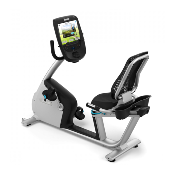
C842, C842i, C846, C846i Upright and Recumbent Cycle
C842, C842i, C846, C846i Bicycle
Warning: This service manual is for use by Precor trained service providers only.
If you are not a Precor Trained Servicer, you must not attempt to service a ny Precor Product;
Call your dealer for service.
This document contains information required to perform the majority of troubleshooting, and
replacement procedures required to repair and maintain this product.
This document contains general product information, software diagnostic procedures (when
available), preventative maintenance procedures, inspection and adjustment procedures,
troubleshooting procedures, replacement procedures and electrical block and wiring diagrams.
To move directly to a procedure, click the appropriate procedure in the bookmark section to the
left of this page. You may "drag" the separator bar between this page and the bookmark section
to change the size of the page being viewed.
© 2004 Precor Incorporated
Unauthorized Reproduction and Distribution Prohibited By Law
Page 1
Advertisement
Table of Contents
Troubleshooting

Subscribe to Our Youtube Channel
Related Manuals for Precor C842


Summary of Contents for Precor C842
- Page 1 C842, C842i, C846, C846i Bicycle Warning: This service manual is for use by Precor trained service providers only. If you are not a Precor Trained Servicer, you must not attempt to service a ny Precor Product; Call your dealer for service.
-
Page 2: Section One - Things You Should Know
Section One - Things You Should Know Right, Left, Front, and Back Conventions In this manual, right, left, front, and back are from the perspective of a user sitting on the C842 or C846, facing the display enclosure. Identifying C846 Bicycles Two generations of C842 and C846 bicycles have been manufactured. -
Page 3: General Information
Do not use accessory attachments that are not recommended by the manufacturer, such attachments might cause injuries or damage to the unit. General Information For the latest exploded view diagram, part number and part pricing information, visit the Precor dealer website at “www.precor.com/connection”. Page 3... - Page 4 C842, C842i, C846, C846i Upright and Recumbent Cycle Required Tools and Equipment The following is a summary of the tools and equipment that may be required when you service a Precor C842, C842i, C846 or C846i Upright or Recumbent Cycle. Tools Phillip and flat-head screwdrivers...
-
Page 5: Section Two - Preventive Maintenance
Regular Preventive Maintenance (Owner) Cleanliness of the cycle and its operating environment will keep maintenance problems and service calls to a minimum. Precor recommends that you perform the following preventive maintenance schedule. After Each Use •... -
Page 6: Quarterly Maintenance
Check the belt tension of both belts per Procedures 5.1 and 5.2. Replace both covers. On-Site Preventive Maintenance (Service Technician) When you are called to service a C842, C842i, C846 or C846i, perform these preventive maintenance activities: • Perform the software diagnostics. Check LED and keypad function. Record the odometer reading. -
Page 7: Procedure 3.1 - Software Access Codes
See Diagram 3.1 for C846 version 1 displays and Diagram 3.2 for C846 i and C846 version 2 displays. The C842 display is not illustrated. The same access code procedures are used on the C842 as on the C846 version... - Page 8 C842, C842i, C846, C846i Upright and Recumbent Cycle Diagram 3.2 - C846i and C846 (version 2) Display Key #7 Reset Key #5 Key #6 & Key #1 Page 8...
-
Page 9: Procedure 3.2 - Accessing The Diagnostic Program
With the start up banner displayed press keys RESET,5,1,7,6,5,7,6,1, sequentially. For C842 and C842i units, skip to step 24. For C846i and C846 version 2 units, skip to step 11. For C846 version 1 units, continue with step 4. - Page 10 C842, C842i, C846, C846i Upright and Recumbent Cycle The battery voltage level will be displayed. Typically, the battery voltage level will be between 6.0 Vdc and 6.2 Vdc. A battery charger in the bike charges the battery as the bike is pedaled.
- Page 11 C842, C842i, C846, C846i Upright and Recumbent Cycle 26. The message KEYBOARD TEST will be momentarily displayed. A representation of each key on the keyboard will be displayed. Pressing a key will cause the representation to change, indicating that the key is functioning normally. Test all of the keyboard keys in this manner.
-
Page 12: Procedure 3.3 - Displaying The Odometer
With the banner scrolling, press keys RESET,6,5, sequentially until the message. The total revolutions will be displayed. For C842 and C842i units, skip to step 19. For C846i and C846 version 2 units, skip to step 8. For C846 version 1 units, continue with step 4. - Page 13 C842, C842i, C846, C846i Upright and Recumbent Cycle 17. The serial number of the unit will be displayed or NO SERIAL NUMBER. If a serial number has not been entered into memory. The serial number is in the upper PCA memory, therefore if the upper PCA is replaced or installed on a different C846 the serial number will be lost or incorrect.
-
Page 14: Procedure 3.4 - Club Settings
On all versions, you must continue pedaling while performing this procedure. For C842 and C842i units, skip to step 23. For C846i and C846 version 2 units, skip to step 11. For C846 version 1 units, continue with step 3. - Page 15 C842, C842i, C846, C846i Upright and Recumbent Cycle 17. The display will momentarily read SET MAX PAUSE TIME. 18. The current maximum pause time will be displayed. Use either of the keys to select the desired setting. The maximum pause time may be set between 1 and 120 seconds.
-
Page 16: Procedure 3.5 - Documenting Software Problems
If you isolated the problem to either the PROM, upper PCA, or lower PCA, include the information you recorded with the malfunctioning PROM or PCA when you ship it to Precor. When a problem occurs, record the following information: •... - Page 17 With the banner displayed, press QUICK START. Select Resistance Level 1 and press ENTER. Operate the C842, C846 or C846i for 4–5 minutes. As you operate the bike, concentrate on the operating sounds made by the unit. Be on the alert for unusual rubbing, hitting, grinding, or squeaking noises.
-
Page 18: Procedure 5.1 - Primary Drive Belt Adjustment
C842, C842i, C846, C846i Upright and Recumbent Cycle Procedure 5.1 - Primary Drive Belt Adjustment For C842, C842i, C846i or C846 version 2 units, skip to step 8. For C846 version 1 units, continue with step 2. Set the on/off switch in the “off” position. - Page 19 Replace the right hand cover per procedure 7.1. Remove the left, right and top covers. Place the belt tension gauge, as shown in Diagram 5.2, on the primary belt. Diagram 5.2 - Primary Belt Tensioning (C842, C842i, C846i and C846 version 2) Belt Gauge...
-
Page 20: Procedure 5.2 - Secondary Drive Belt Adjustment
C842, C842i, C846, C846i Upright and Recumbent Cycle Procedure 5.2 - Secondary Drive Belt Adjustment For C842, C842i, C846i and C846 version 2 units, skip to step 8. For C846 version 1 units, continue with step 2. Set the on/off switch in the “off” position. - Page 21 Replace the left side cover per procedure 7.1. Remove both side covers and the top cover. Place the belt tension gauge, as shown in Diagram 5.4, on the secondary belt. Diagram 5.4 - Secondary Belt Tensioning (C842, C842i, C846i and C846 version 2) Belt Gauge...
-
Page 22: Procedure 5.3 - Recumbent Seat Adjustment
C842, C842i, C846, C846i Upright and Recumbent Cycle Procedure 5.3 - Recumbent Seat Adjustment Perform this procedure if the front to rear movement of the seat is too tight or there is excessive side to side seat wobble. Loosen but do not remove the four mounting screws on the left and right seat adjustment plates. -
Page 23: Procedure 6.1 - Troubleshooting The Interconnect Cables
C842, C842i, C846, C846i Upright and Recumbent Cycle Procedure 6.1 - Troubleshooting the Interconnect Cables For C842, C842i, C846i and C846 version 2 units, skip to step 18. For C846 version 1 units, continue with step 2. Set the on/off switch in the “off” position. - Page 24 C842, C842i, C846, C846i Upright and Recumbent Cycle 14. Check the operation of the cycle as described in Section Four. 15. If the problem is still present re-connect the original upper interconnect cable and proceed with step 9. Troubleshooting the Lower Interconnect cable 16.
- Page 25 C842, C842i, C846, C846i Upright and Recumbent Cycle .Diagram 6.2 - Interconnect Cables, C842, C842i, C846i and C846 version 2 Heart Rate Cables Upper Interconnect Cable Junction Block Lower Interconnect Cable 28. Connect the by-pass interconnect cable to the upper PCA and the junction block.
-
Page 26: Procedure 6.2 - Troubleshooting The Keypad
C842, C842i, C846, C846i Upright and Recumbent Cycle Procedure 6.2 - Troubleshooting the Keypad If the function keys on the electronic console are unresponsive, the problem may be either the upper PCA or keypad. This troubleshooting procedure gives you the information you need to determine which of these components is malfunctioning. - Page 27 C842, C842i, C846, C846i Upright and Recumbent Cycle Start pedalling, if the error 5 is no longer present, the key board is bad. If the error 5 is still present, the upper PCA is bad. Replace either the keyboard (display housing) or the upper PCA as appropriate.
-
Page 28: Procedure 6.3 - Display Does Not Illuminate
Pedal on the cycle for a minimum of 5 seconds. If the display does not illuminate proceed with step 2 for C846 version 1 units or step 12 for C842 and C846 version 2 units and for C842i and C846i units. - Page 29 11. If you have performed all of the previous tests and have not been able to locate the trouble, call Precor customer support. 12. The C842. C846i and C846 version 2 do not use a speed sensor like the C846 version 1 units. Instead the system monitors one of the three phase generator windings. The system monitors AC zero cross.
- Page 30 15. With the unit powered up, measure between test point 19 and test point 20 for approximately 8.5 Vdc. See Diagram 6.6. If the measurement is correct, skip to step 18. Diagram 6.6 - Lower PCA, C842 and C846 version 2 M1, M2...
-
Page 31: Procedure 6.4 - The Rpm Display Is Incorrect
C842, C842i, C846, C846i Upright and Recumbent Cycle Procedure 6.4 - The RPM Display is Incorrect For C842, C842i, C846i and C846 version 2 units, skip to step 8. For C846 version 1 units, continue with step 2. Set the on/off switch in the “on” position. Use the Quick Start key to enter the manual program. - Page 32 If you have performed all of the previous tests and have not been able to locate the trouble, call Precor customer support. The C842 and C846 version 2 do not use a speed sensor like the C846 version 1 units. Instead the system monitors one of the three phase generator windings. The system monitors AC zero cross.
-
Page 33: Procedure 6.5 - No Or Incorrect Pedaling Resistance
Procedure 6.5 - No or Incorrect Pedaling Resistance If the display is not illuminated, go to Procedure 6.3. For C842, C842i, C846i and C846 version 2 units, skip to step 15. For C846 version 1 units, continue with step 3. - Page 34 C842, C842i, C846, C846i Upright and Recumbent Cycle Diagram 6.8 - Alternator, C846 version 1 “P” Terminal “B” Terminal “S” Terminal “EXC” Terminal “E” Terminal 10. With the ohmmeter still on the diode scale, connect the Ω lead of the ohmmeter to the “P”...
- Page 35 C842, C842i, C846, C846i Upright and Recumbent Cycle Diagram 6.9 - Eddy Current Magnet, C842, C842i, C846i and C846 version 2 Generator Eddy Current Magnet 19. If the measurement in step 18 was significantly high or low, replace the generator. The eddy current magnet is furnished with the generator.
-
Page 36: Procedure 6.6 - Unit Does Not Mechanically Operate Freely/Quietly
C842, C842i, C846, C846i Upright and Recumbent Cycle Procedure 6.6 - Unit does not Mechanically Operate Freely/Quietly On C846 version 1 units, set the on/off switch in the off position. Remove both covers per Procedure 7.1, steps 2-7. If the unit is noisy, skip to step 8. If the unit does not turn freely continue with step 4. -
Page 37: Procedure 6.7 - Troubleshooting Hand Held Heart Rate
C842, C842i, C846, C846i Upright and Recumbent Cycle Procedure 6.7 - Troubleshooting Hand Held Heart Rate Circuit Description The hand held heart rate system is actually a dual system, that is, it can accept a heart rate signal from either the hand held heart rate contacts on the unit’s handlebar or from a Polar heart rate chest strap transmitter. - Page 38 C842, C842i, C846, C846i Upright and Recumbent Cycle Set the on/off switch in the “off” position and remove the display housing. Verify the internal chest strap setting is set as shown in Diagram 6.7. Verify that a ferrite bead is installed on the heart rate PCA to upper PCA cable.
- Page 39 C842, C842i, C846, C846i Upright and Recumbent Cycle 15. Set the on/off switch in the “off” position. Refer to Diagram 6.7 for the following measurements. With an ohmmeter measure between the “lower right contact” pin on the J1 connector and the lower right hand held heart rate contact on the handlebar. The reading should be 1 Ω...
- Page 40 C842, C842i, C846, C846i Upright and Recumbent Cycle 25. Set the on/off switch in the “off” position, and remove the spare jumper from J14 of the heart rate PCA. Re-locate all potential sources of radiation. Set the on/off switch in the “on”...
-
Page 41: Procedure 7.1 - Removing Or Replacing One Or Both Covers
C842, C842i, C846, C846i Upright and Recumbent Cycle Procedure 7.1 - Removing or Replacing One or Both Covers For C842, C842i, C846i and C846 version 2 units, skip to step 14. For C846 version 1 units, continue with step 2. - Page 42 14. Remove four screws from the and left side of the top cover. Note It is not necessary to remove the crankarms to remove the covers on the C842 and C846 version 2 units. 15. Remove two screws from the rear of the cover and two screws from the bottom of the left and right covers.
- Page 43 C842, C842i, C846, C846i Upright and Recumbent Cycle 19. Slide the top edge of the left side cover under the top cover and hand start the two remaining top bolts and the two bottom bolts. Hand start the two rear cover bolts.
-
Page 44: Procedure 7.2 - Replacing A Pedal Or Crankarm
C842, C842i, C846, C846i Upright and Recumbent Cycle Procedure 7.2 - Replacing a Pedal or Crankarm For C842, C842i, C846i and C846 version 2 units, skip to step 10. For C846 version 1 units, continue with step 2. Set the on/off switch in the off position. - Page 45 C842, C842i, C846, C846i Upright and Recumbent Cycle Diagram 7.2 - Crankarm, C842, C842i, C846i and C846 version 2 Locking Bolt Mounting Bolt 17. Hand thread the pedal(s) into the crankarm(s). Remember, the left hand pedal is reverse threaded. 18. Torque the pedal(s) to 150 in/lb.
-
Page 46: Procedure 7.3 - Replacing The Seat Or Seat Post (Upright Cycle)
C842, C842i, C846, C846i Upright and Recumbent Cycle Procedure 7.3 - Replacing the Seat or Seat Post (Upright Cycle) On C846 version 1 units, set the on/off switch in the off position. Loosen the seat mounting nut with a box or open end wrench. Lift the seat upward and off of the seat post. -
Page 47: Procedure 7.4 - Replacing All Or Part Of A Seat Carriage Assembly (Recumbent Cycle)
April 1, 2000. For C842, C846i and C846 version 2 units, skip to step 15. For C846 version 1 units, continue with step 2. - Page 48 C842, C842i, C846, C846i Upright and Recumbent Cycle If you are replacing one or all of the seat wheels, hold the wheel bolt with an allen wrench and use a socket wrench to remove the nut from the wheel assembly. Repeat this procedure for each wheel being replaced.
- Page 49 C842, C842i, C846, C846i Upright and Recumbent Cycle Diagram 7.7 - Seat Guide 11. Loosen the bolts that retains the front end of each of the seat guides to th e cycle frame (See Diagram 7.7). Raise the rear of the seat guides and securely tighten the front bolts. The guide must be up as far as possible or the seat will not slide freely.
- Page 50 C842, C842i, C846, C846i Upright and Recumbent Cycle the seat. Remove the plate. The cable may be stuck to the plate with double sided tape. 19. Remove the two screws that fasten the plate to the seat rail. Extract enough cable from the seat rail to access the cable connectors.
- Page 51 C842, C842i, C846, C846i Upright and Recumbent Cycle 22. Remove the plate that covers the hand held heart rate cable on the bottom of the seat. See Diagram 7.11. The cable may be stuck to the plate with double sided tape.
- Page 52 C842, C842i, C846, C846i Upright and Recumbent Cycle Diagram 7.12 - Internal Hand Held Heart Rate Cable Black Tape Blue Tape 27. Feed the wire ends out of the handlebars so that the black wire comes out of the top of the handlebars and the red wire comes out of the bottom of the handlebar.
-
Page 53: Procedure 7.5 - Replacing The Column
C842, C842i, C846, C846i Upright and Recumbent Cycle Procedure 7.5 - Replacing the Column For C842, C846i and C846 version 2 units, skip to step 14. For C846 version 1 units, continue with step 2. Set the on/off switch in the off position. - Page 54 C842, C842i, C846, C846i Upright and Recumbent Cycle Set the column at it’s mounting position and hand start all four column mounting bolts. Securely tighten the column mounting bolts. Ensure that the column is securely fastened and does not wiggle or move.
-
Page 55: Procedure 7.6 - Replacing The Upper Or Lower Interconnect Cable Or Heart Rate Cable
Procedure 7.6 - Replacing the Upper or Lower Interconnect Cable or Heart Rate Cable For C842, C842i, C846i and C846 version 2 units, skip to step 18. For C846 version 1 units, continue with step 2. Set the on/off switch in the off position. - Page 56 C842, C842i, C846, C846i Upright and Recumbent Cycle 19. Remove the display housing per Procedure 7.12, steps 1-4. Disconnect the interconnect cable from J1 of the upper PCA or the heart rate cable from J4 of the hand held heart rate PCA, as required.
-
Page 57: Procedure 7.7 - Replacing The On/Off Switch (C846 Version 1 Only)
C842, C842i, C846, C846i Upright and Recumbent Cycle Procedure 7.7 - Replacing the On/Off Switch (C846 version 1 only) Set the on/off switch in the off position. Remove the right hand cover per Procedure 7.1. Remove the black wires from the positive terminal of the battery (the positive battery terminal is denoted with a red stripe, see Diagram 7.9). -
Page 58: Procedure 7.8 - Replacing The Speed Sensor (C846 Version 1 Only)
C842, C842i, C846, C846i Upright and Recumbent Cycle Procedure 7.8 - Replacing the Speed Sensor (C846 version 1 only) Set the on/off switch in the off position. Remove the right hand cover per Procedure 7.1. Diagram 7.14 - Speed Sensor Mounting... -
Page 59: Procedure 7.9 - Replacing The Battery
C842, C842i, C846, C846i Upright and Recumbent Cycle Procedure 7.9 - Replacing the Battery For C842, C846i and C846 version 2 units, skip to step 11. For C846 version 1 units, continue with step 2. Set the on/off switch in the off position. If the cycle is equipped with an external power adapter, disconnect the power adapter from the cycle. - Page 60 C842, C842i, C846, C846i Upright and Recumbent Cycle Test the operation of the cycle per Section 4. 10. Replace the cover per Procedure 7.1. 11. If the cycle is equipped with an external power adapter, disconnect the power adapter from the cycle.
-
Page 61: Procedure 7.10 - Replacing The Load Resistor (C846 Version 1 Only)
C842, C842i, C846, C846i Upright and Recumbent Cycle Procedure 7.10 - Replacing the Load Resistor (C846 version 1 only) Caution When the cycle is operated the load resistor will become hot. Before proceeding with this procedure, be sure that the load resistor has cooled sufficiently to be safely handled. -
Page 62: Procedure 7.11 - Replacing The Lower Pca
C842, C842i, C846, C846i Upright and Recumbent Cycle Procedure 7.11 - Replacing the Lower PCA For C842, C842i, C846 and C846 version 2 units, skip to step 11. For C846 version 1 units, continue with step 2. Set the on/off switch in the off position. - Page 63 C842, C842i, C846, C846i Upright and Recumbent Cycle 10. Replace the cover per Procedure 7.1. 11. Disconnect the optional external power adapter, if equipped. 12. Remove the left, right and top covers. 13. Disconnect the red wire from the battery. Disconnect all of the wires from the lower PCA.
-
Page 64: Procedure 7.12 - Replacing The Display Housing Or Upper Pca
Procedure 7.12 - Replacing the Display Housing or Upper PCA For C842, C842i, C846i and C846 version 2 units, skip to step 14. For C846 version 1 units, continue with step 2. Set the on/off switch in the off position. - Page 65 C842, C842i, C846, C846i Upright and Recumbent Cycle Orient the keypad cable as noted in step 5 and reconnect the keypad cable to the J3 connector. 10. Assemble the replacement or original upper PCA and display housing as required and replace and tighten the upper PCA mounting screws.
-
Page 66: Procedure 7.13 - Replacing The Alternator (C846 Version 1 Only)
C842, C842i, C846, C846i Upright and Recumbent Cycle Procedure 7.13 - Replacing the Alternator (C846 version 1 only) Note: The flywheel is balanced on the alternator. The replacement alternator will be furnished with a flywheel and be balanced as a unit. The flywheel should only be removed from the alternator if absolutely necessary. - Page 67 Set the new alternator/flywheel in it’s mounting position, insert the upper and lower mounting bolts and hand tighten. Replace the secondary drive belt. Attach a drive belt tension gauge (Precor part # 20030-108 or equivalent) to the upper span of the secondary drive belt. Rotate the alternator until the tension gauge reads 60 pounds ±...
-
Page 68: Procedure 7.14 - Replacing The Primary Drive Belt
C842, C842i, C846, C846i Upright and Recumbent Cycle Procedure 7.14 - Replacing the Primary Drive Belt For C842, C842i, C846i and C846 version 2 units, skip to step 8. For C846 version 1 units, continue with step 2. Set the on/off switch in the off position. - Page 69 Remove the right side cover. Loosen but do not remove the locknut retaining the idler pulley. See Diagram 7.23. This will remove tension from the primary belt. Diagram 7.23 - Primary Drive Belt, C842, C842i, C846i and C846 version 2 Primary Pulley...
-
Page 70: Procedure 7.15 - Replacing The Secondary Drive Belt
C842, C842i, C846, C846i Upright and Recumbent Cycle Procedure 7.15 - Replacing the Secondary Drive Belt For C842, C842i, C846i and C846 version 2 units, skip to step 11. For C846 version 1 units, continue with step 2. Set the on/off switch in the off position. - Page 71 12. Loosen the jam nuts on the secondary belt tension adjustment bolt. Loosen the adjustment bolt to remove tension from the secondary belt. See Diagram 7.25. remove the secondary belt. Diagram 7.25 - Secondary Drive Belt, C842, C842i, C846i and C846 version 2 Secondary Belt...
-
Page 72: Procedure 7.16 - Replacing The Primary Pulley Or Primary Bearings
Procedure 7.16 - Replacing the Primary Pulley or Primary Bearings For C842, C842i, C846i and C846 version 2 units, skip to step 12. For C846 version 1 units, continue with step 2. Remove the primary drive belt per Procedure 7.14, steps 1-3. - Page 73 C842, C842i, C846, C846i Upright and Recumbent Cycle 11. Replace the primary drive belt per procedure 7.14, steps 4-6. This procedure is complete. 12. Remove the left, right and top covers. 13. Remove the left and right crankarms per Procedure 7.2. Slide the left pulley cover off of the primary pulley axle.
- Page 74 Procedure 7.17 - Replacing the Secondary Pulley, Intermediate Pulley or Secondary Bearings For C842, C842i, C846i and C846 version 2 units, skip to step 14. For C846 version 1 units, continue with step 2. Remove the primary drive belt per Procedure 7.14, steps 1-3.
- Page 75 C842, C842i, C846, C846i Upright and Recumbent Cycle If you are not replacing the secondary bearings, skip to step 9. Using a long thin tool, tap the secondary bearings out of the frame. Set one of the replacement bearings in place in the frame as far as possible by hand. Place a 1-3/4 inch pipe against the bearing so the pipe wall aligns with the outer bearing race.
- Page 76 C842, C842i, C846, C846i Upright and Recumbent Cycle 24. Insert an allen wrench into the left end of the secondary pulley shaft, thread the secondary axle onto the secondary axle and tighten with a 20030-119 secondary sheave tool and a 1/2 inch drive socket wrench.
-
Page 77: Procedure 7.18 - Replacing The Idler Pulley
C842, C842i, C846, C846i Upright and Recumbent Cycle Procedure 7.18 - Replacing the Idler Pulley For C842, C842i, C846i and C846 version 2 units, skip to step 8. For C846 version 1 units, continue with step 2. Remove the primary drive belt per Procedure 7.14, steps 1-3. -
Page 78: Procedure 7.19 - Replacing The Prom
C842, C842i, C846, C846i Upright and Recumbent Cycle Procedure 7.19 - Replacing the PROM Anti-static kits (part number 20024-101) can be ordered from Precor. The PROM and the associated printed circuit assembly (PCA) are static sensitive. Anti- static devices must be used and all anti-static precautions must be followed during this procedure. - Page 79 Remove all of the wiring from the lower PCA. Loosen the secondary belt adjustment belt to remove tension from the secondary belt. Remove the four generator mounting bolts. See Diagram 7.30 Diagram 7.30 - Generator Mounting C842, C842i, C846i and C846 version 2 Lower PCA Generator...
- Page 80 C842, C842i, C846, C846i Upright and Recumbent Cycle 11. Refer to Diagram 6.6 and replace the lower PCA wiring as follows. Connect the wires from the external power jack to connector J4 on the lower PCA. Connect the two red wires from the eddy current magnet to terminals M1 and M2 of the lower PCA (it does not matter which red wire goes on terminal M1 or M2).
- Page 81 C842, C842i, C846, C846i Upright and Recumbent Cycle Procedure 7.21 - Primary Axle or Bearing Replacement (C842, C842i, C846i and C846 version 2 only) Remove the left and right side covers. Remove both the left and right hand pedals. Refer to Procedure 7.2.
- Page 82 If the left hand bearing requires replacement, replace it with Precor part number 45441-103. The right hand bearing is part of the primary pulley assembly. If the right hand bearing requires replacement, replace Precor part number 45439-102 primary pulley assembly.
- Page 83 C842, C842i, C846, C846i Upright and Recumbent Cycle 12. Thread the 32 mm nut, removed in step 4, onto the left side of the primary axle and torque it 60 inch-pounds. 13. Route the primary belt around the primary pulley, over the idler pulley and around the secondary axle as shown in Diagram 7.23.
- Page 84 C842, C842i, C846, C846i Upright and Recumbent Cycle Wiring Diagram - C846 version 1 Page 84...
- Page 85 C842, C842i, C846, C846i Upright and Recumbent Cycle Block Diagram - C846 version 1 Page 85...
- Page 86 C842, C842i, C846, C846i Upright and Recumbent Cycle Wiring Diagram - C842, C842i, C846i and C846 version 2 Page 86...
- Page 87 C842, C842i, C846, C846i Upright and Recumbent Cycle Block Diagram - C842, C842i, C846i C846 version 2 Magnet Page 87...
Need help?
Do you have a question about the C842 and is the answer not in the manual?
Questions and answers