Table of Contents
Advertisement
Quick Links
Advertisement
Table of Contents

Subscribe to Our Youtube Channel
Related Manuals for HAKO HAKOMATIC B 90 CL


Summary of Contents for HAKO HAKOMATIC B 90 CL
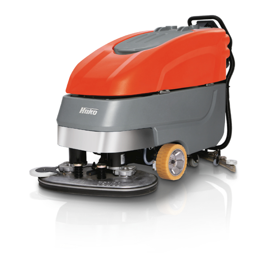
- Page 1 Instruction Manual Hakomatic B 90 CL (7062.30/.40/.41/.42/.43)
-
Page 2: Introduction
The Schrubbmaschine is for attach- the contents of this manual. good characteristics of the Hakomatic B ment to the Hakomatic B 90 CL. The If repair work has to be performed make 90 CL should justify the confidence you Hakomatic B 90 CL is a vacuum srub- sure that only genuine spare parts are demonstrated by making this purchase. -
Page 3: Notes Of Warranty
AG or your freight forwarder confirm The maintenance work has to be perfor- such damage. Mail notification and med by an authorized Hako service waybill to: center and confirmed in the "Mainte- nance certificate" which is the warranty Hako GmbH document. -
Page 4: Table Of Contents
5.8.1 Clean dirt hopper ..36 vironment ....8 Hako System Maintenance . 23 5.8.2 Remove brushes ..36 Labels at the Machine . -
Page 5: Safety Information
Safety information Safety information Safety and Warning Symbols All paragraphs in this manual referring to your personal safety, the safety of your machine and the environment pro- tection are attributed one of the follo- wing warning symbols: Symbol Hazardous for ... Description Safety Provisions persons and goods... -
Page 6: General Provisions
• Persons being trained by qualified • Use only cleaning agents suitable for charging procedure and comply with Hako technicians only are authori- automatic machines (low-foaming) the operating instructions of the sed to operate, service and repair... -
Page 7: Maintenance Instructions
Battery Hako service center. ting down before working in the area • Respect the operating instructions of • Observe the maintenance activities of a lifted tank lid. -
Page 8: Information For Protection Of Environment
According to the crossed dustbin la- bel these batteries must not be ad- ded to the normal waste. Provide for agreement with the Hako contract dealer on return and disposal accor- ding to § 8 BattV. -
Page 9: Labels At The Machine
Replace missing or illegible labels (Fig. 1/2) immediately. C = Do not clean the machine by means of high-pressure cleaning equipment Hako nameplate (Fig. 1/1) (Fig. 1/2) Machine identification number (Fig. 1/2) Soiled water drain hose (Fig. 1/3) Fig.1... -
Page 10: First Operation
Hako contract kage or damage. Proceed with the following to set the dealer. Your Hako dealer will be infor- 2. -
Page 11: Operation
First Operation Operation turns automatically into the neutral posi- Transport rides 1. Switch the machine on with the key tion. The machine stops. Protect the To move the machine to the place switch. machine against unintentional move- where it is to be used, switch it on, lift- 2. -
Page 12: Operation
Operation Operation Method of operation General The Hakomatic B 90 CL is a vacuum scrubbing machine for wet cleaning of hard-surfaced floors. 3.1.1 Brush Head Lower brush head (Fig. 3/1) via tip switch before scrubbing. The brushes rotate and water supply switches on au- tomatically. -
Page 13: Squeegee
Internet under means of sealing strips. Squeegee is lo- braking. www.hako.com wered via tip switch. Simultaneously, 3.1.6 Batteries and Charger the suction turbine switches on. The The machine is equipped with an auto- suction turbine works independent of di- matic charger unit (Fig. -
Page 14: Operating And Indicating Ele- Ments
Operation Operating and Indicating Ele- ments 3.2.1 Operating Panel 1 Display 2 Key switch 3 Battery charge indication 4 LDS indicator 5 Symbol brush drive 6 Symbol suction turbine drive 7 Hourmeter 8 Symbol Service indicator 9 Symbol Parking brake 10 Symbol Silence Kit (optional) 11 Symbol fresh water dosage 12 Tip-switch Silence Kit (optional) - Page 15 Operation Display (Fig. 4/1) 1.1.1.1 This panel allows centralized moni- toring of functions and detection of all LDS indicator (Fig. 4/4) Hourmeter (Fig. 4/7) available operating modes. Upon switching on, the LDS indication Upon switching on, the hourmeter is output on the panel to show the cur- briefly displays the software version rent battery charge condition during and the last error code.
- Page 16 Operation Parking brake symbol (Fig. 4/9) Silence Kit tip-switch (optional) (Fig. Scrubbing tool symbol (optional) This symbol appears if control lever is in 4/12) (Fig. 4/15) neutral position and travel drive will be This tip-switch is used to change suc- This symbol appears when scrubbing locked.
- Page 17 Tip-switch brush head and suction Tip-switch squeegee and suction turbine (Fig. 4/16) turbine (Fig. 4/19) This tip-switch (Hako tip-switch) is used This tip-switch is used to lower/lift-out to switch the brush drive and the suc- the squeegee and to switch the suction tion turbine ON and OFF with simulta- turbine ON and OF.
-
Page 18: At The Machine
Operation 3.2.2 At the machine 1 Accelerator lever 2 Opening of fresh water tank 3 Soiled water vacuum hose 4 Fresh water filter 5 Soiled water drain hose 6 Fresh water level indication 7 Brush ejector 8 Power connection charger unit Fig.5... - Page 19 Operation Accelerator lever (Fig. 5/1) While fresh water flows from tank to squeegee, it is cleaned by the filter ele- With the machine being switched on, ment. the accelerator lever allows continuous regulation of speed. If pulled to maxi- Soiled water drain hose (Fig. 5/5) mum position, maximum speed is attai- ned.
- Page 20 Operation Dirt hopper guiding rail (Fig. 6/1) The dirt hopper located at the cylindrical broom head is fastened by a guiding rail. This dirt hopper may be easily re- moved for cleaning. Lever for cylindrical broom seating (Fig. 6/2) This lever (both sides) is used to re- lease/lock the cylindrical broom seating.
-
Page 21: Technical Data
Technical Data Technical Data Metric unit Plate brush 85 Roll brush 70 Machine length Machine height Machine width without Squeegee Machine width with Squeegee Working width Squeegee width Surface performance theoretical m²/h 3400 2800 Service voltage Nominal power drive motor Nominal power suction motor Nominal power brush motor 2x935... - Page 22 Technical Data Noise emission Metric unit Standard Soundproo- Soundproo- fing pack fing pack/ Silence Kit The sound pressure level measured under maximum conditions of use (LwA) according to DIN EN 60335-2-72 amounts to: dB (A) The sound pressure level measured (at the ear of the driver) under normal conditions of use (LpA) according to DIN EN dB (A) 60335-2-72 amounts to:...
-
Page 23: Maintenance And Care
(daily or weekly). The dri- personnel only. Please contact your lo- ver/operator will be instructed upon de- cal Hako Service Centre or Hako con- livery of the machine. tract dealer. We cannot be held liable Hako-System Maintenance I :... -
Page 24: Maintenance Document
Maintenance and Care Maintenance Document Handing over Hako-System-Maintenance I Hako-System-Maintenance II Hako-System-Maintenance I 125 operating hours 250 operating hours 375 operating hours Upgrade Workshop stamp Workshop stamp Workshop stamp Test drive Handing over to the customer Instruction carried out on:... -
Page 25: Maintenance Schedule
Maintenance and Care Maintenance Schedule Hako-System Maintenance Custo- The daily and weekly maintenance in- tervals are to be performed by the cu- stomer/operator. Interval To be performed daily weekly Fill clear water tank and proceed to chemical agent dosage Charge batteries... - Page 26 Maintenance and Care Hako-System Maintenance I The following maintenance woks are to be performed by an authorised Hako Service workshop. Interval To be performed every 125 hours of operation Check battery charger Check tank lid sealing of the soiled water tank and replace if required...
- Page 27 Interval To be performed every 250 hours of operation Perform maintenance works according to Hako-System Maintenance I Inspect steering rollers for tread damages and bearing slackness and replace if required Check drain hose of the soiled water tank and replace if required...
- Page 28 Interval To be performed every 500 hours of operation Perform maintenance works according to Hako-System Maintenance II Clean travel drive motor from carbon dust and check carbon brushes for smooth operation and wearing and replace carbon brushes if required Clean brush motors from carbon dust and check carbon brushes for smooth opera-...
-
Page 29: Battery Systems
Maintenance and Care Battery Systems 1 LDS display 2 Charger indicator 3 Charger 4 Mains cable charger 5 Battery plug 6 Batteries 7 Soiled water tank 8 Support 9 Wiring diagram Handling and changes of the batteries may take place only by maintenance staff. -
Page 30: Charge Batteries
Contact your battery the charger has to be 2. Switch off machine by key switch. local Hako contract partner for return adjusted only by Hako contract 3. Open empty soiled water tank (Fig. and recycling according to § 8 BattV! workshops. -
Page 31: Fresh Water Tank
Maintenance and Care Solution Tank 1 Solution tank 2 Marker 3 Fill level hose 4 Solution filter 5 Tank lid Fig.8... -
Page 32: Fill Fresh Water Tank
Maintenance and Care 5.5.1 Fill Solution Tank 5.5.3 Clean Solution Filter Fill solution tank (Fig. 8/1) before work Check solution filter (Fig. 8/4) at weekly or as required. Park vehicle on level intervals and clean or replace if re- ground. Open tank lid (Fig. 8/5) and fill quired. -
Page 33: Soiled Water Tank
Maintenance and Care Soiled Water Tank 1 Soiled Water Tank 2 Drain hose 3 Suction filter 4 Tank lid Fig.9... -
Page 34: Empty Soiled Water Tank
Maintenance and Care 5.6.1 Empty Soiled Water Tank 5.6.2 Clean Soiled Water Tank Clean soiled water tank (Fig. 9/1) at Clean soiled water tank (Fig. 9/1) at daily intervals, as required or upon daily intervals or as required. acoustic signal (increased suction turbi- 1. -
Page 35: Plate Brush Head
Maintenance and Care Plate brush head 5.7.1 Clean Brushes 5.7.2 Change Brushes Clean brushes of the brush head (Fig. Check brushes of the brush head for 1 Toggle-type fastener 10/2) at daily intervals or as required. wearing at weekly intervals. Replace 2 Brush head Press brush ejectors (Fig. -
Page 36: Roll Brush Head
Maintenance and Care Roll brush head 5.8.1 Clean dirt hopper 5.8.2 Remove brushes 1 Brush toothing Clean dirt hopper (Fig. 11/2) at daily in- 1. Release brush seating (Fig. 11/7) by 2 Dirt hopper tervals or as required. locking lever (Fig. 11/8). 3 Roll brush head Remove dirt hopper from the right ma- 2. -
Page 37: Squeegee
Maintenance and Care Squeegee 5.9.1 Cleaning the Squeegee 5.9.2 Changing the Sealing Strips Check the squeegee (Fig. 12/1) daily Check the inner and outer sealing strips 1 Squeegee and clean as necessary. on the squeegee (Fig. 12/1) weekly for 2 Star-shaped knob To clean it lift the squeegee out, pull off signs of wear. -
Page 38: Adjust Sealing Strips
Maintenance and Care 5.9.3 Adjusting the Sealing Strips Angle Adjustment The angle adjustment is the decisive factor in ensuring that the sealing strips on the squeegee lie evenly on the floor. 1. Park the machine on a level surface and lower the squeegee. 2. - Page 39 Maintenance and Care Height Adjustment The height adjustment is set to 3 mm at the factory. If streaks are produced, de- spite an optimum angle adjustment, the clearance between the rollers and floor must be adjusted by changing the num- ber of washers on the holder.
- Page 40 The machine may be used only for must be agreed on with your authorized operation on plane areas with a maxi- Hako dealer in accordance with the Bat- mum inclination of up to 10 %. tery Law § 6 and § 8 (BattG)
-
Page 41: Ec-Declaration Of Conformity
EC Declaration of Conformity (corresponds to EC Directive 2006/42/EC) Reference was made to the following Name of the authorized person who Hako GmbH standards and/or norms and/or techni- compiles technical documents for Hamburger Straße 209-239 cal specifications to ensure proper im-... - Page 42 Spitzentechnik für eine saubere und schönere Umwelt Superior technology for a cleaner and better environment Hako GmbH · Hamburger Str. 209-239 · D-23843 Bad Oldesloe · (0 45 31) 806-0 · Fax (0 45 31) 806-338...
Need help?
Do you have a question about the HAKOMATIC B 90 CL and is the answer not in the manual?
Questions and answers