Table of Contents
Advertisement
Advertisement
Table of Contents

Subscribe to Our Youtube Channel
Related Manuals for HAKO Hakomatic B 1050 W


Summary of Contents for HAKO Hakomatic B 1050 W
- Page 1 Instruction Manual Hakomatic B 1050 W (7580.22)
-
Page 2: Introduction
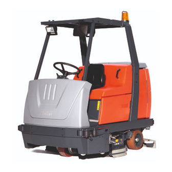
We would like to emphasize that no le- Intended use gal claims can be asserted in respect of Dear Customer, The Hakomatic B 1050 W is a large- any information provided in this manual. Please read this original manual tho- area scrubber-drier designed for wet... -
Page 3: Notes On Warranty
Maintenance work must gard to the damage and the damage re- emed liable for any damage resulting be performed at authorized Hako ser- port is sent to us together with the from unauthorized modifications to the vice centers and confirmed in the consignment note: vehicle. -
Page 4: Table Of Contents
Environmental protection . . . 11 in the driver's cab ..29 5.3.2 Hako system maintenance I. 61 Labels on the vehicle ..12 3.2.2 Left-hand operating panel . . 32 5.3.3 Hako system maintenance II 64... - Page 5 Contents 5.4.6 Total discharge signal 5.7.4 Adjusting the locking lever EC Declaration transducer (TSG) ..70 for the brush holder ..79 of Conformity ..87 Solution tank.
-
Page 6: Safety Information
Safety Information Safety Information Safety and warning labels All texts related to personal safety, sa- fety of the vehicle and environmental protection are assigned the following symbols throughout the operating ma- nual: Symbol Hazardous for ... Definition Danger persons Safety information to prevent the development of or property hazardous situations resulting from ignoring or failing to follow instructions or prescribed work procedures. -
Page 7: General Information
Safety Information General information venting errors when operating the Operating information • The Hakomatic B 1050 W fulfills all equipment and ensuring trouble-free • Before starting the vehicle up for the the applicable safety and health re- operation. first time, the battery to be used must quirements stipulated in the EU di- •... - Page 8 Safety Information • The Hakomatic B 1050 W must be • If the floor is excessively wet, check wise imprints of the brush could be subjected to an inspection in respect the vehicle for leaks and that the produced on the floor.
-
Page 9: Maintenance Information
• When working in the area of the rai- sted for them at an authorized Hako sed seat console, it must be pivoted service center. • Operating personnel must complete up fully to prevent it accidentally clo- •... -
Page 10: Particular Risks
Safety Information clothing when handling the battery diately and remove the key from the nation, e.g. from metal dust. (e.g. protective gloves, finger stalls, key switch! • Never lay any metallic objects or protective goggles). tools on batteries. Risk of short cir- 1.5.1 Electronics •... -
Page 11: Environmental Protection
Return and recycling of old bat- teries must be agreed on with Hako's authorized dealers in accordance with § 6 and § 8 BattG (Battery Law). -
Page 12: Labels On The Vehicle
Safety Information Labels on the vehicle The following safety and warning labels are attached to the vehicle where easily legible. Missing or illegible labels must be replaced immediately. Company logo (Fig. 1/1) (Fig. 2/1) Read the operating manual, maximum gradi- ent and ban on cleaning using a high-pressure washer (Fig. - Page 13 Safety Information Maximum water temperature for solution to be filled (Fig. 2/6) Drive direction selector: Forward or reverse (Fig. 2/3) Release parking brake (Fig. 2/4) Apply parking brake (Fig. 2/5) Fig. 2...
- Page 14 Safety Information Solution drainage (Fig. 3/7) The solution is drai- ned via the hose which hangs to the left of this label. Waste water drainage (Fig. 3/8) The waste water is drained via the hose which hangs to the right of this label. No waste water drainage (Fig.
-
Page 15: Starting Up
Only technicians from your local autho- first time. information on the subject is considered rized Hako dealer are allowed to provi- unnecessary for this manual. de initial instruction on the vehicle. The The seat console must be pivo-... -
Page 16: Prior To Starting Up For The First Time
(refer to Sec- tion 4). If you ordered the rotary brus- hes together with the vehicle, the rotary Fig. 5 brushes are normally already installed by the authorized Hako dealer prior to 1 Locking lever delivery. Fig. 4 2 Brush holder... - Page 17 Starting Up Fig. 7 1 Catch Fig. 8 2 Housing 3 Rotary brush 1 Pin Fig. 6 2 Brush support 1 Housing 6. Lay one hand under the rotary brush 3 Catch 2 Contact surfaces (Fig. 7/3) and slide it together with 4 Rotary brush 3 Rotary brush the catches (Fig.
- Page 18 Starting Up onto the pins (Fig. 8/1) of the brush support (Fig. 8/2). Ensure that the contact sur- faces (Fig. 6/2) are clean. Clean them thoroughly, if ne- cessary, before fitting them on the brush holder (Fig. 6/4). 8. Slide the locking lever (Fig. 5/1) to the middle of the device and hold it there.
-
Page 19: Installing And Adjusting The Squeegee
Starting Up 2.3.2 Installing and adjusting the squeegee Installing the squeegee 1. Switch on the key switch. 2. Lower the squeegee holding attach- ment: Press the button for the squeegee and suction turbine so that the green control lamp lights up. 3. -
Page 20: Adjusting The Driver's Seat
Section 5.7.1. ses, lines and tanks must show no 3. Fill the solution tank and cleaning The Hakomatic B 1050 W is equipped signs of leaks or damage. If neces- agent in accordance with the manuf- with a driver's seat which can be adju- sary, clear up any defects before acturer's mixing directives. -
Page 21: Operation
Method of operation sures that coarse dirt, such as cable The Hakomatic B 1050 W is a scrub- ties, cigarette ends etc., does not slide ber-drier designed for wet cleaning under the sealing strip of the squeegee rough and structured hard floors inside and, thus, impair the vacuuming results. - Page 22 Operation Deflectors (Fig. 12/2) To the right and left of the rotary brush head, near the floor, are two deflectors which, when in their working position, prevent water splashing to the sides and guide the waste water to the center of the vehicle so that it can be vacu- umed up better.
-
Page 23: Squeegee
Operation 3.1.2 Squeegee (Fig. 12/3) The squeegee, which projects at the sides, is fixed to the Hakomatic B 1050 W so that it can pivot and swing. This enables it to evade obstacles in the current cleaning track and pivot back. Its strong suction capacity ensures the waste water is vacuumed up fully even on uneven floors and in bends, leaving... -
Page 24: Suction Turbines (Suction)
• at 2 l/min. approx. 87 minutes The two suction turbines are located on anced for the Hakomatic B 1050 W. • at 4 l/min. approx. 43 minutes the rear panel of the solution tank and These products meet the requirements •... -
Page 25: Traction Drive
(Fig. 14/3) for each individu- 3.1.7 Brakes • IUIa characteristic curve al cell and with aquamatic plugs The Hakomatic B 1050 W is equipped • 230 V power supply line (Fig. 14/4) to enable simple refilling of with a service brake and a parking Pay attention to the safety information water. -
Page 26: Options
Operation 3.1.9 Options The basic vehicle can be supplemented by further components. The order and spare parts numbers of these compo- nents are in brackets. • Cab safety roof (7582) (Fig. 15/2) Purpose: To protect the driver, e.g. from objects falling from warehouse shelving. - Page 27 - Suction nozzle with rubber lips (7766) (7883) - Tool holder and attachment parts (7311.10) With regard to accessories such as rotary brushes, suction lips etc., (Fig. 15/4) please re- fer to our spare parts catalog in the Internet at www.hako.com.
- Page 28 Operation 1 Working lights 2 Cab safety roof 3 Flashing beacon 4 Vacuuming tool 5 Side brush unit Fig. 15...
-
Page 29: Operating And Indicator Elements
Operation Operating and indicator elements 3.2.1 Operating elements in the driver's cab 1 Left-hand operating panel 2 Steering wheel 3 Safety catch (to release the parking brake) 4 Accelerator to drive forwards or backwards 5 Service brake 6 Driving direction selection switch (forwards/reverse) 7 Right-hand operating panel 8 Parking brake... - Page 30 Service brake (Fig. 16/2) el: forwards or reverse. (Fig. 16/5) • The Hakomatic B 1050 W is steered • Forward or reverse drive (according • In order to slow down the vehicle and by the steering wheel. to the driving direction selection...
- Page 31 Operation Driving direction selection switch Parking brake (forwards/reverse) (Fig. 16/8) • The pedal to the left of the steering (Fig. 16/6) column serves to apply the parking • It serves to select the driving direc- brake to the rear wheels. tion: •...
-
Page 32: Left-Hand Operating Panel
11 Buttons for controlling the solution supply 12 Button to reduce solution quantity 13 Button to switch solution supply on and off 14 Button to increase solution quantity 15 Green Hako button for simultaneous activation of scrubbing unit and vac- uuming function Fig. 17... - Page 33 (Fig. 17/1) The indicator field enables Indicator for function faults The counter only operates when con- the Hakomatic B 1050 W to provide sumers are switched on (e.g. hydraulic feedback on the operating status of the (Fig. 17/4) or brush motor, suction turbine).
- Page 34 Operation Battery and charge ing and the brush is lowered or raised Button for rotary brush accordingly. If the side brush unit is control indicator drive switched on, the green control lamp (Fig. 17/6) After switch- (Fig. 17/9) This button serves lights up.
- Page 35 Hako button. When the The solution quantity previously set re- sumption used during cleaning can be Hako button has been pressed, the mains unaltered (last station memory).
-
Page 36: Right-Hand Operating Panel
Operation 3.2.3 Right-hand operating panel (Fig. 3) 1 Key switch 2 Horn 3 Switch for spraying/vacuuming tool 4 Switch for flashing beacon 5 Switch for working lights Fig. 18... - Page 37 "Operating hours counter" in par- after one hour at the latest. The agraph 3.2.2): When a functional fault actually Hakomatic B 1050 W is ready for occurs, an acoustic signal is use while this display appears. The 1 Software version also issued and the red control alarm indicator is activated.
- Page 38 Operation Switch for spraying/ vacuuming tool (Fig. 18/3) This switch switches the vacuuming tool on or off. The suction tool is an op- tional accessory. If it is not installed, the switch has no function. Switch for flashing beacon (Fig. 18/4) The flashing beacon is an optional accessory.
-
Page 39: Operating Elements On The Vehicle
Operation 3.2.4 Operating elements on the vehicle 1 Waste water filter 2 Solution tank filling neck 3 Lid lock 4 Cover, solution tank 5 Cover, recovery tank 6 Waste water draining hose 7 Solution draining hose 8 Left-hand rear door 9 Rear panel frame lock 10 Rear panel frame 11 Right-hand rear door... - Page 40 Operation Recovery tank Lid lock Solution draining hose (Fig. 19/1+5) (Fig. 19/3) (Fig. 19/7) The waste water filter (Fig. 19/1) is lo- The lock prevents the lid falling shut. To The draining hose for solution hangs to cated under the recovery tank lid lock the lid, move the bar and latch in the left of the suction turbines.
- Page 41 Operation 12 Seat console 13 Electrical compartments 14 Side door 15 Battery trough Fig. 20...
- Page 42 Operation Seat console Battery trough (Fig. 20/12) (Fig. 20/15) The battery trough contains the 18 indi- The driver's seat is mounted on the seat vidual battery cells and serves to ena- console. The seat console can be pivot- ble a quick change of battery. The ed up using the handle in order to ac- battery trough is provided with fitting cess the batteries and electric system.
-
Page 43: Operation
Operation • The vehicle is equipped with a safety • Insert the key in the key switch The Hakomatic B 1050 W can be driven shutdown via a seat contact (dead (Fig. 21). for a maximum of 5 minutes on surfaces man's switch). -
Page 44: Stopping And Parking
• Press the green Hako but- good condition. If the sealing ton on the left-hand operat- strips are damaged, change ing panel. - Page 45 Operation Wet scrubbing (basic cleaning) Vacuuming dry • Press the “Button for squeegee and suction tur- If you do not want to vacuum the floor • Press the “Button for bine” on the left-hand oper- dry in the same working procedure be- squeegee and suction tur- ating panel.
-
Page 46: Switching The Vehicle Off
3.3.5 Switching the vehicle off ence will ensure that you quickly find • Turn the key from lock position 1 to out which is the right Hako cleaning position 0. The vehicle is no longer agent and the optimum dosage to ready to operate. -
Page 47: After Finishing Work
Operation After finishing work 5. Check the solution filter, refer to 1. Drive to a suitable service or parking Section 5.5.4. area. 6. Check the sealing strips and suction hose, refer to Section 5.8. An appropriate service and 7. Check the electrical equipment, parking area must have a solid functions and settings. -
Page 48: Function Faults
• If the problem reoccurs, determine the shaft (e.g. tape and such). cause of overheating; contact an authorized Hako service center, if necessary. 1.2.6.1. The brushes remain stopped Foreign bodies • Check the brushes for foreign bodies and remove them, as necessary. -
Page 49: Other Function Faults
• Allow the motor to cool down. brushes and shaft • If the problem reoccurs, determine (e.g. tape and such). the cause of overheating; contact an authorized Hako service center, if necessary. 2.3.6.1. The side brushes remain stopped Foreign bodies (e.g. tape or •... -
Page 50: Technical Data
Technical Data Technical Data Dimensions Vehicle length (with brush head and squeegee) Vehicle height, without/with cab safety roof 140/200 Vehicle width, without/with squeegee 113/126 Vehicle width with side brush unit (option) Working width Brush head Squeegee With side brush unit (option) Area coverage Theoretical at 7.5 kph m²/h... - Page 51 Technical Data Driving performance Driving speed, forwards/reverse 8.0/4.0 Working speed, maximum, forwards Climbing capacity, driving mode (max. 1 min) Climbing capacity, work mode (max. 5 min) Turning circle diameter, outer 3.35 Lock in aisle: minimum width of aisle 2.40 Operating time with one battery charge Approx.
- Page 52 Technical Data Brakes Service brake: Hydraulic Rear drum brake, with automatic adjustment: diameter/width 180/40 Brake fluid (e.g. ATE) Parking brake: Rear cable brake, adjustable: diameter/width 180/40 Tank volume Fixed panel tank: solution / waste water 174/174 Flow rate, adjustable from/to l/min.
- Page 53 Technical Data Electrical installation Power supply Type of current Nominal power, total 5500 Protection class VDE 0700 Battery compartment: length/width/height 950/610/465 Noise emission value The sound power level (L ) measured according to EN 60335-2-72 under dB (A) normal under working conditions is: The sound pressure level (L ) measured according to DIN EN 60335-2-72 (at dB (A...
- Page 54 Technical Data Special equipment: Order number 4202 Driving batteries Trough battery 18 cells, cell type 80 PzS (PzS = armor plate insulation) V/Ah 36/480 Weight Dimensions: length/width/height 750/610/462 Order number 4001.02 Battery charger Power supply Charge output 36/60 Charging time Order number 7582 Cab safety roof (including rear-view mirror)
- Page 55 Technical Data Special equipment: Rotary brushes Plastic PA 0.7 for light to medium accumulations of dirt Order number 7887 SIC PA 6.12 grain 500 for medium to heavy accumulations of dirt Order number 7846 SIC PA 6.12 grain 180 for heavy to extreme accumulations of dirt Order number 7890 SIC PA 6.12 grain 80 for extreme accumulations of dirt...
-
Page 56: Maintenance And Service
Hako system maintenance I: Hako system maintenance: (Every 250 operating hours) Service • ensures the Hako working vehicle is Must be completed by a skilled techni- General information always ready for operation (preventi- cian in an authorized Hako service cen-... -
Page 57: Maintenance Report
Maintenance and Service Maintenance report Handover Hako System Maintenance I Hako System Maintenance II Hako System Maintenance I 250 operating hours 500 operating hours 750 operating hours Upgrading Workshop Stamp Workshop Stamp Workshop Stamp Test drive Handover to customer Instruction... -
Page 58: Maintenance Schedule
Maintenance and Service Maintenance schedule The following maintenance work must It relates to the daily and weekly main- be completed by the customer at the tenance work. 5.3.1 Hako system maintenance, intervals stipulated. customer Interval Activity Daily Directly prior to starting operation:... - Page 59 Maintenance and Service Interval Activity Daily Clean the large particle suction filter Clean the fresh water filter Check the battery charge; recharge as necessary Before completing the weekly elements to a function test in order to maintenance work described check whether the vehicle is ready for below,subject all the operating operation.
- Page 60 Maintenance and Service Interval Activity Weekly Check the recovery tank through the inspection hole at the top for signs of premature wear (due to glass splinters, metal chips, grit, etc.) or damage and clean it Check the condition of the side brush unit and replace the side brushes as necessary Check the vehicle is clean;...
-
Page 61: Hako System Maintenance
Maintenance and Service 5.3.2 Hako system maintenance I The following maintenance work must be completed by an authorized Hako service center. Interval Activity Every 250 operating hours Check the battery in terms of acid level, acid density and voltage per cell; clear up any defects as... - Page 62 Maintenance and Service Interval Activity Every 250 operating hours Check the rotary brush head, repair as necessary (continued): Check the spraying pattern of the nozzles, clean the nozzles if necessary Check the drive belt seal for cleanliness and no leakage. To do this, clean any dirt and fluff from the drive belt chamber, check the ventilation of the rotary brush motors in the belt chamber, clean as necessary.
- Page 63 Maintenance and Service Interval Activity Every 250 operating hours Check the electrical safety functions: parking brake, recovery tank float switch Check the visual appearance of the vehicle: color, corrosion and presence of all signs and labels Check the vehicle is clean; clean it, if necessary Test drive and test all function and safety-relevant components including brake tests Produce test report UVV-BGV-TÜV-VDE Inspection label...
-
Page 64: Hako System Maintenance Ii
Interval Activity Every 500 operating hours Complete all activities in Hako system maintenance I, see paragraph 5.3.2 In addition: Check the output of the hydraulic motor (forwards, reverse); clear defects as necessary Check the carbon brushes of the hydraulic motor; replace, if necessary Check the brush motor output (left and right);... -
Page 65: Iii/S (Safety Check)
Interval Activity Every 1000 operating hours Complete all activities in Hako system maintenance I and II, see paragraph 5.3.2 and paragraph 5.3.3 In addition: Check the brake linings on the rear wheels; change as necessary Change the brake fluid in the service brake Including visual inspection, test drive, test report, inspection label and logbook see paragraph 5.3.2... -
Page 66: Battery System
Maintenance and Service Battery system The Hakomatic B 1050 W is equipped with a low-maintenance trough battery, refer to Sections 3.1.8 and 4. The batte- ry is comprised of 18 individual cells in a parallel circuit. 1 Battery and charge control indicator... -
Page 67: Charging Batteries
Section 1.5.2 as well as the in- initial battery charge routine, ries during the charging process. formation on servicing and refer to Section 2.2. Hako as- maintenance in the battery do- • Connect the battery plug (Fig. 23/4) sumes no liability for damage cuments. -
Page 68: Servicing The Driving Batteries
Topping up the battery is completed via 1. Park the machine on a level area of If the Hakomatic B 1050 W is the connection coupling, the aquamatic floor. equipped with a cab safety plug (Fig. -
Page 69: Installing The Trough Battery
Maintenance and Service 6. Lift the battery trough out of the ve- hicle using the lifting gear. 5.4.4 Installing the trough battery Set the key switch to position 0 (refer to paragraph ”Key switch” in Section 3.2.3) and remove the key. 1. -
Page 70: Disposing Of Batteries
Maintenance and Service If the Hakomatic B 1050 W is 5.4.5 Disposing of batteries 5.4.6 Total discharge signal trans- fitted with a cab safety roof, the Used batteries with the recycling sym- ducer (TSG) trough battery can only be in- bol contain reusable commodities. -
Page 71: Solution Tank
Maintenance and Service Solution tank 1 Lid seal 2 Tank cap 3 Opening to recovery tank (airing and venting) 4 Solution tank 5 Solution filter 6 Ball cock 7 Screw cap 8 Draining hose Fig. 25... -
Page 72: Filling The Solution Tank
Maintenance and Service 5.5.1 Filling the solution tank 5.5.2 Emptying the solution tank 5.5.3 Cleaning the draining hose Fill the solution tank (Fig. 25/4) with If the vehicle is to be left unused for a fresh water and cleaning agent before longer period, the solution tank should •... -
Page 73: Recovery Tank
Maintenance and Service Recovery tank 1 Tank cap 2 Lid seal 3 Recovery tank 4 Air intake filter 5 Screw cap 6 Waste water draining hose 7 Cleaning flap Fig. 26... -
Page 74: Emptying The Recovery Tank
Maintenance and Service 5.6.1 Emptying the recovery tank 5.6.2 Cleaning the recovery tank 3. Pull out the run-off plate (Fig. 27/3) Clean the recovery tank (Fig. 26/3) eve- 4. Release the flap lock: Turn the wing The recovery tank (Fig. 26/3) ry day or as necessary. -
Page 75: Cleaning The Draining Hose Cap
Maintenance and Service 8. After finishing cleaning the tank, clo- 5.6.3 Cleaning the draining hose 1. Pull the filter sieve from the suction se the flap and push the run-off plate pipe and clean with water. back in place. • Clean the draining hose cap on a Remove the filter sieve com- 9. -
Page 76: Rotary Brush Head
(Fig. 29/2), refer to Section 2.3.1. Normally, however, the authorized Hako workshop will install them for you prior to delivery. Before working on the rotary brushes, switch off the rotary... -
Page 77: Emptying And Cleaning The Waste Container
Maintenance and Service 5.7.1 Emptying and cleaning the Cleaning the waste container waste container 1. Wash and clean the waste container (Fig. 30/1) with water. The waste container must be emptied and cleaned at least Installing the waste container once a day. If the vehicle is Position the waste container (Fig. -
Page 78: Changing The Rotary Brushes
Maintenance and Service 5.7.2 Changing the rotary brushes Check the rotary brushes on a weekly basis for signs of wear. When a rotary brush has worn to a dia- meter of approx. 10 cm, the rotary brus- hes must be replaced by new ones (diameter of new rotary brush: 13.6 cm). -
Page 79: Cleaning The Contact Surfaces
Maintenance and Service Removing the brush holder 5.7.3 Cleaning the contact surfaces 5. Remove the brush holder (Fig. 31/6) Each time the rotary brushes are (refer to paragraph ”Removing the 1. Slide the locking lever (Fig. 31/1) to changed, all the contact surfaces brush holder”) and adjust the oval- the middle of the device and hold it (Fig. -
Page 80: Installing New Rubber Deflector Strips
If this is 3. Remove the old rubber deflector the case, contact an authorized Hako strips (Fig. 32/2). service center to have the rotary brush 4. Position the new rubber deflector head readjusted. -
Page 81: Direction Of Rotation Of The Rotary Brushes
Controlling and adjusting the direction of rotation may only be carried out at an authorized Hako service center. When viewing the front left side of the vehicle, the front rotary brush (Fig. 33/ 1), viewed in the driving direction, must rotate counterclockwise and the rear ro- tary brush (Fig. -
Page 82: Squeegee
Maintenance and Service Squeegee 1 Squeegee holding attachment 2 Wing nuts 3 Connection nozzle 4 Sealing strip (rear) 5 Support strip (rear) 6 Clamping rail (rear) 7 Knurled nut The squeegee is also equipped with front sealing and support strips and clamping rail (Fig. -
Page 83: Changing The Sealing Strips
In the case of problems with the front 1. Disassemble the squeegee, refer to wheel, please contact an authorized Section 5.8.2 Hako service center. 2. Unscrew the knurled nuts (Fig. 34/ The front wheel may only be 3. Remove the clamping rail, support... -
Page 84: Electrical Installation
All the lifting elements and brush mo- • Loosen the screws in the foot plate • Install the wheel in place. tors in the Hakomatic B 1050 W are and remove the foot plate. • Screw on and tighten the wheel nuts equipped with safety fuses and electro- •... -
Page 85: Cleaning The Vehicle
Maintenance and Service 5.11 Cleaning the vehicle 5.12 Transporting and towing Transporting the vehicle • Clean the vehicle on a weekly basis, • When transporting the vehicle using Loading refer to Section 5.3.1. lifting gear to the site of use, the •... - Page 86 Maintenance and Service Towing the vehicle If it should become necessary to tow the Hakomatic B 1050 W, only do it on a level floor and at a maximum towing speed of 4 kph. The tow rope must be attached at the front lashing points.
-
Page 87: Ec Declaration Of Conformity
EU Directive: Ludger Lüttel declares that the products DIN EN 60335-2-72 Hakomatic B 1050 W DIN EN 61000-6-2 Type: 7580.22, 7580.24 DIN EN 55012 o which this declaration relates, conform to the relevant provisions of Bad Oldesloe, 28.12.2009... - Page 88 Spitzentechnik für eine saubere und schönere Umwelt Superior technology for a cleaner and better environment · · Hako-Werke GmbH Stammwerk und Hauptverwaltung Headquarter · · · Hamburger Str. 209-239 D-23843 Bad Oldesloe +49 4531 806-0 Fax +49 4531 806-338...
Need help?
Do you have a question about the Hakomatic B 1050 W and is the answer not in the manual?
Questions and answers