Advertisement
Micro AcCELLerator
3X-C70B-3XR
Bulletin 628043 • Revision A • March 2015 Page 1 of 4
GENERAL INFORMATION
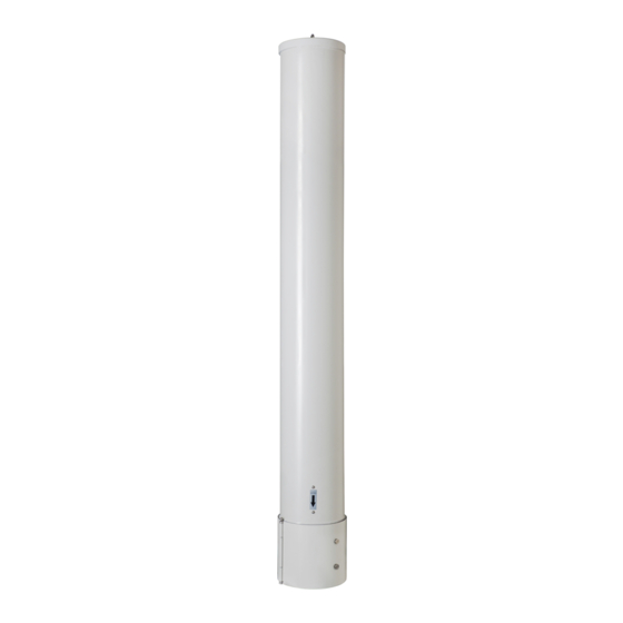
The 3X-C70B-3XR antenna (Figure 1) is a compact, tri-sector
antenna solution equipped with two hinged covers at the
base of the antennas which enable access to the RF and
AISG ports plus the mounting interface. Since mounting
locations and surfaces will vary, CommScope does not
provide the mounting bolts or associated hardware required
to properly install this antenna. It is the responsibility of
qualified personnel to determine the best method for
securely anchoring the base plate of the antenna to the
mounting surface.
After removing the antenna from its shipping container
carefully inspect it to ensure there is no shipping damage. If
the antenna is to be hoisted into position, ensure the lifting
eye bolt is correctly installed. Ensure the antenna is securely
held during hoisting to avoid rotation on the lifting eye bolt.
DO NOT remove the EYE BOLT after installation, otherwise
water ingress to antenna may occur.
Covers
Figure 1. 3X-C70B-3XR
Antennas
TM
Eye Bolt
Radome
Installation Instructions
CommScope Infrastructure Academy offers installation training.
INSTALLATION INSTRUCTIONS
1. Loosen the thumb screws (Figure 2), and open the
covers.
Thumb Screws
Cover
Figure 2. Hinged Covers
Cover
Thumb Screws
Base Plate
(continued on page 2)
Advertisement
Table of Contents

Related Manuals for CommScope 3X-C70B-3XR


Summary of Contents for CommScope 3X-C70B-3XR
-
Page 1: Installation Instructions
Bulletin 628043 • Revision A • March 2015 Page 1 of 4 GENERAL INFORMATION INSTALLATION INSTRUCTIONS The 3X-C70B-3XR antenna (Figure 1) is a compact, tri-sector 1. Loosen the thumb screws (Figure 2), and open the antenna solution equipped with two hinged covers at the covers. - Page 2 3X-V65A-3XR Antenna CommScope (Continued from page 1) Bulletin 628043 • Revision A • March 2015 Page 2 of 4 Refer to Figures 3, 4 and 5 for mounting and boresite Using customer supplied hardware, mount the base plate alignment. It is recommended that the mounting holes of the antenna to the mounting surface.
- Page 3 CommScope (Continued from page 2) Bulletin 628043 • Revision A • March 2015 Page 3 of 4 4. Remote Electrical Tilt Connection. Attach the RF cables to the antenna input connectors and torque to 25-30 Nm (Figure 5). A single AISG 8 Pin DIN Male input connector interface is provided which will accept a cable assembly Route RF cable along metal rails, etc.
- Page 4 Hinweis: CommScope lehnt jede Haftung oder Verantwortung für Schäden ab, die aufgrund unsachgemäßer Installation, Überprüfung, Wartung oder Demontage auftreten. Atenção: A CommScope abdica do direito de toda responsabilidade pelos resultados de práticas inadequadas e sem segurança de instalação, inspeção, manutenção ou remoção.
Need help?
Do you have a question about the 3X-C70B-3XR and is the answer not in the manual?
Questions and answers