Table of Contents
Advertisement
Advertisement
Table of Contents

Related Manuals for CommScope ValuLine VHLP Series


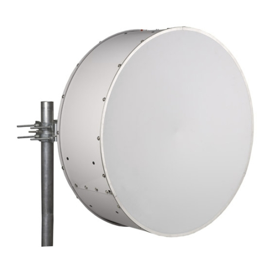
Summary of Contents for CommScope ValuLine VHLP Series
- Page 2 © 2008 CommScope, Inc. All rights reserved. U.S.A., Canada, Mexico: 1-800-255-1479 Andrew Solutions is a trademark of CommScope. All trademarks identified by ® or ™ are registered trademarks or trade- or 1-888-235-5732 marks, respectively, of CommScope. This document is for planning purposes only and is not intended to modify or supplement U.K.: 0800 250055...
-
Page 3: Section 1 Contents & Introduction
INTRODUCTION This instruction describes how to unpack and adjust a factory assembled VHLP(X)4 antenna. Mount to the left of the supporting structure. It can also be configured to mount to right - refer to full antenna assembly instructions on CommScope.com... -
Page 4: Section 2 Safety Instructions
INSTALLATION SECTION 2 7835454 INSTRUCTIONS SAFETY INSTRUCTIONS Page 4 of 17... - Page 5 INSTALLATION SECTION 2 7835454 INSTRUCTIONS SAFETY INSTRUCTIONS Page 5 of 17...
- Page 6 INSTALLATION SECTION 2 7835454 INSTRUCTIONS SAFETY INSTRUCTIONS Page 6 of 17...
-
Page 7: Section 3 Equipment And Tools
INSTALLATION SECTION 3 7835454 INSTRUCTIONS EQUIPMENT AND TOOLS Page 7 of 17 Table 1 Supplied Equipment and Tools Item Description Assembled antenna Strut Kit Integration Unit * Flange Hardware Kit * 1 or 2 *Either Item C (Integration Unit) or Item D (Flange Hardware Kit) are supplied. Tools TOOL REQUIREMENTS Bolt Diameter in MM... -
Page 8: Section 4 Unpacking
INSTALLATION SECTION 4 7835454 INSTRUCTIONS UNPACKING Page 8 of 17 Unpacking Loose hardware Do not discard these parts Loose hardware... - Page 9 INSTALLATION SECTION 4 7835454 INSTRUCTIONS UNPACKING Page 9 of 17 Non-integrated antennas Non-integrated antennas have supplied flange hardware kit this factory feed fitted flange outputs will vary dependent on antenna this will vary dependent on model antenna model OEM direct mount radio integration (certain models only).
-
Page 10: Installation
INSTALLATION SECTION 5 7835454 INSTRUCTIONS MOUNT ATTACHMENT AND ALIGNMENT Page 10 of 17 Where required, fit radio integration unit at this stage - refer to instructions supplied with integration unit. 38Nm 5% SLING Elevation adjustment nut Loosen, do not remove. NEVER WALK UNDER HOISTED LOADS... -
Page 11: Section 5 Mount Attachment And Alignment
INSTALLATION SECTION 5 7835454 INSTRUCTIONS MOUNT ATTACHMENT AND ALIGNMENT Page 11 of 17 Loosen screws Pan Left Pan Right Azimuth adjustment Adjust eyebolt. On completion tighten all hardware to 38Nm ± 5% Adjustment Range ±15° Torque to 38Nm 5%... - Page 12 INSTALLATION SECTION 5 7835454 INSTRUCTIONS MOUNT ATTACHMENT AND ALIGNMENT Page 12 of 17 Antenna Offset Left Antenna Offset Right Refer to full antenna assembly instructions on www.commscope.com for details on how to switch mount offset...
- Page 13 INSTALLATION SECTION 5 7835454 INSTRUCTIONS MOUNT ATTACHMENT AND ALIGNMENT Page 13 of 17 Strut to be loosely fitted until alignment is complete then tighten all fixings to torque specified. Strut to be attached to center hole. Tighten all hardware to a torque of 38Nm 5%...
- Page 14 INSTALLATION SECTION 5 7835454 INSTRUCTIONS MOUNT ATTACHMENT AND ALIGNMENT Page 14 of 17 For attachment to circular structural members only Torque to 38Nm 5% Torque to 38Nm 5% MIN PIPE 50mm MAX PIPE 115mm Struts must be attached to a circular structural member capable of supporting 2704N in line with TIA-222.
- Page 15 INSTALLATION SECTION 5 7835454 INSTRUCTIONS MOUNT ATTACHMENT AND ALIGNMENT Page 15 of 17 • Image shown is intended as a guide for strut alignment • Strut must be attached to an appropriate, structural mounting point • Strut angle must not exceed maximum specified •...
-
Page 16: Section 6 Transition Polarisation Adjustment
INSTALLATION SECTION 6 7835454 INSTRUCTIONS TRANSITION POLARISATION ADJUSTMENT Page 16 of 17 Single polarisation Step 1 Remove blanking plate, screws, washers o-ring (gasket) Vertical polarisation Flat provided to aid fine polarisation transition Step 2 Step 3 adjustment After fine adjustment, tighten Horizontal polarisation Loose screws a turn to allow... -
Page 17: Section 7 General Information
INSTALLATION SECTION 7 7835454 INSTRUCTIONS GENERAL INFORMATION Page 17 of 17...
Need help?
Do you have a question about the ValuLine VHLP Series and is the answer not in the manual?
Questions and answers