Advertisement
Quick Links
Installation Instructions
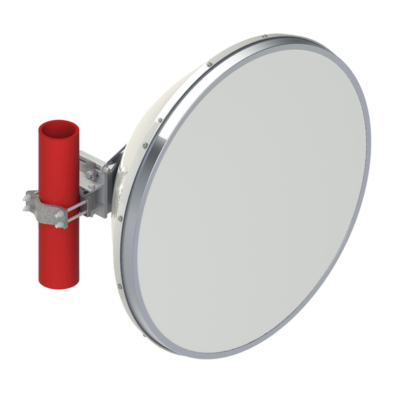
ValuLine ® VHLP3 Antennas
Installation Safety & Equipment
SERVICE PERSONNEL
Installation, maintenance or removal of equipment must be carried out by authorized personnel having the appropriate technical training, education
and experience necessary to be cognizant of hazards during installation and service, and of measures to minimize any danger to themselves or
any other person.
SAFETY REGULATIONS
Always use mandatory local safety regulations, instructions in this manual shall be used as a supplement to the local regulations.
In case of conflict between the safety instructions in this manual and local safety regulations, the local mandatory safety regulations shall prevail.
CommScope will not accept responsibility for accidents resulting from non-compliance to regulations
INSTALLATION HARDWARE
Do not use any components (for example screws and nuts) other than those enclosed with the equipment or recommended by CommScope.
Use protective wear to avoid skin contact with conductive grease. Keep away from mouth. Wash thoroughly after use with liberal amounts
of liquid soap and rinse with water. Do not store open near food or food substances.
Contents: Oil, clay & zinc dust.
HOISTING & WORKING AT HEIGHTS
Some working areas involve the risk of accidents caused by falling or by falling objects
•
Use only tested and approved hoisting equipment in accordance with the instructions supplied with the equipment.
•
Appropriately trained personnel must operate the hoisting device.
•
Never walk under hoisted loads.
GENERAL MAINTENENCE
•
The antenna is designed such that minimal maintenance is required. Equipment should be inspected once a year by qualified personnel to
verify proper installation, maintenance, and condition of equipment to ensure trouble free operation.
CLEANING OF ANTENNA
•
If subsequent cleaning of the antenna is required use water and mild detergent.
HARDWARE AND TOOLS
Stainless Steel Hardware
Torque (Nm 5%)
Galvanised Steel Hardware
Torque (Nm 5%)
Brass Hardware
Torque (Nm 5%)
Spanner and Sockets
All trademarks identified by ® or ™ are registered trademarks or trademarks, respectively, of CommScope, Inc. This document is for planning purposes only and is not intended to modify or supplement any
specifications or warranties relating to CommScope products or services. CommScope is committed to the highest standards of business integrity and environmental sustainability, with a number of CommScope's
facilities across the globe certified in accordance with international standards, including ISO 9001, TL 9000, and ISO 14001.
Further information regarding CommScope's commitment can be found at
Visit our website or contact your local CommScope representative for more information.
For technical assistance, customer service, or to report any missing/damaged parts, visit us at: www.commscope.com/SupportCenter
This product is covered by one or more U.S. patents or their foreign equivalents. For patents, see www.commscope.com/ProductPatent/ProductPatent.aspx
READ MANUALS FULLY BEFORE UNPACKING,
Fastener Torques & Tool Sizes
Thread
M3
1.0
5.5
(mm A/F)
www.commscope.com/About-Us/Corporate-Responsibility-and-Sustainability.
IMPORTANT!
ASSEMBLING & INSTALLING ANTENNA
M4
M5
M6
2.2
4.5
7.7
-
-
-
-
-
-
-
-
7
8
10
UNLESS STATED OTHERWISE
Bulletin
Model Version
M8
M10 M12 M16 M20
19
38
-
-
-
38
60
95
-
-
-
-
13
17
19
24
7706805
page
1 of 14
Version
10
Status
RE
Rev
L
01
Status
Rev
Y
RE
-
185
95
30
Advertisement

Related Manuals for CommScope ValuLine VHLP3


Summary of Contents for CommScope ValuLine VHLP3
- Page 1 UNLESS STATED OTHERWISE All trademarks identified by ® or ™ are registered trademarks or trademarks, respectively, of CommScope, Inc. This document is for planning purposes only and is not intended to modify or supplement any specifications or warranties relating to CommScope products or services. CommScope is committed to the highest standards of business integrity and environmental sustainability, with a number of CommScope’s facilities across the globe certified in accordance with international standards, including ISO 9001, TL 9000, and ISO 14001.
- Page 2 ValuLine ® VHLP3 Antennas 7706805 Bulletin page 2 of 14 Version Status Model Version Status OVERVIEW This instruction describes how to assemble a VHLP(X)3 antenna. The antenna can be mounted with the mount offset to the left or to the right. Offset left is described in this bulletin, however the images showing offset right installation are shown at the end of this document.
- Page 3 ValuLine ® VHLP3 Antennas Bulletin 7706805 page 3 of 14 Version Status Model Version Status EQUIPMENT Item Description Contained in Kit Part No Reflector Radome Rim Radome Feed VF-3-FR-14 Feed Installation Kit Mount: Elevation Adjustment Assembly 7679156 Mount: Azimuth Adjustment Clamp 7671897 Mount Hardware Kit 7700025...
- Page 4 ValuLine ® VHLP3 Antennas Bulletin 7706805 page 4 of 14 Version Status Model Version Status EQUIPMENT...
- Page 5 ValuLine ® VHLP3 Antennas Bulletin 7706805 page 5 of 14 Version Status Model Version Status Unpacking Remove top insert and rim kit through top opening of carton Remove Vint kit and feed kit box through flap openings Leave brace frame attached to assist assembly of feed and radome.
- Page 6 ValuLine ® VHLP3 Antennas Bulletin 7706805 6 of 14 page Version Status Model Version Status Feed attachment and alignment Align slot with rib 6GHz, 7GHz and 11GHz Feed Assembly Apply conductive grease to Assemble 4x screws surface indicated Tighten screws to a torque of SEE SAFETY 1.4Nm 5% NOTE PAGE 1...
- Page 7 ValuLine ® VHLP3 Antennas Bulletin 7706805 7 of 14 page Version Status Model Version Status Radome attachment and alignment Rim edges aligned with Align rim edges with marked indicators on radome. indicators on radome. Note: The radome is not packing material. Note position of alignment red sticker.
- Page 8 ValuLine ® VHLP3 Antennas Bulletin 7706805 page 8 of 14 Version Status Model Version Status Radome attachment and alignment Align holes in rim with slots in reflector Note position of radome alignment red sticker to reflector Assemble 16x self tapping screws, lock washers and washers in a diagonal sequence.
- Page 9 ValuLine ® VHLP3 Antennas Bulletin 7706805 page 9 of 14 Version Status Model Version Status Mount Attachment and Alignment Carefully lay antenna on clear, flat ground. Then remove brace and discard fixings. Do not apply excessive weight to antenna assembly.
- Page 10 ValuLine ® VHLP3 Antennas Bulletin 7706805 10 of 14 page Version Status Model Version Status Mount Attachment and Alignment st. st. Apply grease to areas indicated SEE SAFETY NOTE PAGE 1 st. st. galv galv galv galv st. st. galv G3 galv galv galv...
- Page 11 ValuLine ® VHLP3 Antennas Bulletin 7706805 page 11 of 14 Version Status Model Version Status Mount Attachment and Alignment st. st. Apply grease to surface 38Nm 5% indicated SEE SAFETY NOTE PAGE 1 st. st. 38Nm 5% st. st. 38Nm 5%...
- Page 12 ValuLine ® VHLP3 Antennas Bulletin 7706805 page 12 of 14 Version Status Model Version Status Mount Attachment and Alignment galv 38Nm 5% SLING 90-120mm Pole Secure assembled mount to pole ensuring clamp bolts are seated correctly. This mount can only be used for pole diameters from 90-120 mm Pole to be structural engineer approved rigid structural support...
- Page 13 ValuLine ® VHLP3 Antennas Bulletin 7706805 page 13 of 14 Version Status Model Version Status Mount Attachment and Alignment Loosen screws G1 Loosen screws G2 Pan Left Pan Right Azimuth adjustment Adjust eyebolt. On completion tighten screws G1 to 50Nm ± 5% and screw G2 to 38Nm ±...
- Page 14 ValuLine ® VHLP3 Antennas Bulletin 7706805 page 14 of 14 Version Status Model Version Status Mount Attachment and Alignment Antenna Offset Left For installation of Transition unit see manual: Installing an transition Unit to a 0.3m, 0.6m, 0.9m, 1.2m and 1.8m antenna. Fit radio per instructions For installation of Intregration unit see manual: Installing an integrated Dual Polarization Unit to a...
Need help?
Do you have a question about the ValuLine VHLP3 and is the answer not in the manual?
Questions and answers