Table of Contents
Advertisement
Quick Links
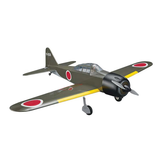
SPECIFICATIONS
Wingspan:
56.5 in [1435 mm]
Length:
46 in [1170 mm]
2
Wing Area:
537in
[ 34.6 dm
WARRANTY
Great Planes
®
Model Manufacturing Co. guarantees this
kit to be free from defects in both material and workmanship at
the date of purchase. This warranty does not cover any
component parts damaged by use or modification. In no case
shall Great Planes' liability exceed the original cost of
the purchased kit. Further, Great Planes reserves the right to
change or modify this warranty without notice.
In that Great Planes has no control over the final assembly or
material used for final assembly, no liability shall be assumed nor
accepted for any damage resulting from the use by the user of
the final user-assembled product. By the act of using the
user-assembled product, the user accepts all resulting liability.
If the buyer is not prepared to accept the liability
associated with the use of this product, the buyer is
READ THROUGH THIS MANUAL BEFORE STARTING CONSTRUCTION. IT CONTAINS IMPORTANT
INSTRUCTIONS AND WARNINGS CONCERNING THE ASSEMBLY AND USE OF THIS MODEL.
© 2016 Great Planes Model Mfg. A subsidiary of Hobbico,
Weight:
5 – 5.75 lbs [ 2270 – 2610 g]
Wing
21– 25 oz/ft
Loading:
2
]
Radio:
4− 5 Channel
®
Inc.
INSTRUCTION MANUAL
Engine:
2
[ 64 – 76 g /dm
2
]
Electric:
advised to return this kit immediately in new and
unused condition to the place of purchase.
To make a warranty claim send the defective part or item to
Hobby Services at the address below:
3002 N. Apollo Dr. Suite 1
Champaign IL 61822 USA
Include a letter stating your name, return shipping address, as
much contact information as possible (daytime telephone
number, fax number, e-mail address), a detailed description of
the problem and a photocopy of the purchase receipt. Upon
receipt of the package the problem will be evaluated as quickly
as possible.
airsupport@greatplanes.com
.46−.55 cu in (7– 9 cc) 2-stroke
or .70 cu in (11.5 cc) 4-stroke glow
RimFire .32, 4S 3300 mAh LiPo,
75 A ESC, 13 x 8 E propeller
Hobby Services
Champaign, Illinois
(217) 398-8970, Ext 5
GPMA1209
Advertisement
Table of Contents

Related Manuals for GREAT PLANES ZERO


Summary of Contents for GREAT PLANES ZERO
-
Page 1: Instruction Manual
3002 N. Apollo Dr. Suite 1 Champaign IL 61822 USA In that Great Planes has no control over the final assembly or material used for final assembly, no liability shall be assumed nor Include a letter stating your name, return shipping address, as... -
Page 2: Table Of Contents
Radio / Servos (2) 6" [150mm] servo extensions (TACM2092) and a Y-harness (FUTM4130) are required for the A minimum of 4-channels is required to fl y the Zero. The aileron servos. Tactic TTX650 is recommended because of its simple, fl exible... -
Page 3: Glow Engine
Glow Engine The Zero is suited for a .46 – .55 2-stroke or .70 4-stroke. The O.S. Max .55AX (OSMG0557) is illustrated in this manual with a Bisson Pitts-style muffl er (BISG4046). Other Accessories for a Glow Engine 1/4" [6.4mm] R/C foam rubber (HCAQ1000) -
Page 4: Kit Contents
17. Velcro Strap 18. Laser-cut Wood Parts PREPARATIONS Note: The covering on your Zero requires less heat than you may be used to if you’re already familiar with iron-on coverings – too much heat causes seams and edges to draw away from each other causing wavy, uneven edges or exposed balsa. -
Page 5: Assemble The Wing
4. Drill 1/16" [1.6mm] holes for the servo mounting screws ASSEMBLE THE WING in the wing and for the control horn screws on the aileron (use care not to drill through the top of the aileron). Mount the 1. Attach a 6" servo and horn, make the pushrod and hook up the aileron [150mm] servo... - Page 6 9. Use two M2 x 8 machine-thread screws, washers, M2 12. Lightly wet the threads of four M3 set screws with nuts and a little threadlocker to loosely fasten two hump threadlocker and mount the main wheels to the main landing straps to the outside of one of the wheel covers.
-
Page 7: Assemble The Fuselage
17. After the epoxy has hardened remove the clamps and tape. ASSEMBLE THE FUSELAGE 15. A few paper towels cut into small squares and denatured alcohol will be useful for cleaning off excess epoxy during the next step while gluing the wing halves together. 1. - Page 8 5. Remove the stab and fi n from the fuselage. Use 30-minute epoxy to glue the tail gear wire into the rudder and glue the stab and fi n into the fuselage. Use more paper towel squares dampened with denatured alcohol to wipe away residual epoxy.
-
Page 9: Install The Electric Motor
8. Use medium-grit sandpaper to roughen the fl ange on the belly pan and remove any minute inconsistencies so glue will adhere. Test-fi t the belly pan to the bottom of the wing and make any adjustments necessary for a good fi t. 11. - Page 10 2. Press 4-40 blind nuts into the front plate and glue them 5. Drill 1/16" [1.6mm] pilot holes through the “O” marks in with CA. in the fi rewall, then enlarge the holes with a 5/32" [4mm] drill. Insert 6-32 blind nuts into the back of the holes. 3.
- Page 11 8. Assemble the motor and mount it to the motor mount 11. Glue the two balsa sticks across the back of the box with four 4-40 x 1/2" Phillips screws and #4 lock washers fi rewall so the screws don’t puncture the LiPo battery in the and fl at washers and threadlocker—notice that the motor event of a crash.
-
Page 12: Mount The Glow Engine
Skip to Install the Radio on page 15. Mount the Glow Engine The instructions illustrate installation of an O.S. Max .55 AX with a Bisson No. 04046 Pitts-style muffl er. If using a different engine and/or a different muffl er, slight adjustments may be required in the way your engine is rotated on the fi rewall, but as long as you align the four engine mount screws with the circle inscribed on the fi rewall, the engine will be in the... -
Page 13: Hook Up The Throttle
[125 mm] from the fi rewall. Tighten the engine mount screws and hold the engine in place with a clamp. Use a Great Planes Dead-Center Hole Locator or similar tool to mark the engine mount bolt hole locations onto the mount. -
Page 14: Mount The Cowl
Mount the Cowl The following instructions illustrate how to mount the cowl and cut the muffl er exhaust holes with the included template for the O.S. Max .55AX with the Bisson muffl er. If using a different engine and/or muffl er, mount the muffl er to the engine fi rst, then cut the cowl as necessary for the muffl er and the exhaust opening. -
Page 15: Install The Radio
4. Use compressed air or warm, soapy water to thoroughly clean all metal fi lings from the muffl er. Mount the muffl er to the engine and mount the cowl to the fuselage enlarging the exhaust cutouts as necessary to install the cowl over the muffl er tubes. - Page 16 Mark the pushrods where they cross the holes in the servo arms. Install a Pilot (Optional) A Great Planes 1/7-scale painted military pilot was used (GPMQ9117). 1/16" [1.5 mm] Servo Arm 5. Disconnect the clevises from the horns and remove the pushrods from the fuselage.
-
Page 17: Prepare The Model For Flight
Note: the throws are measured at the widest part of the aileron, elevator and rudder. 3. Glue strips of balsa to the base These are the recommended control surface throws: serving as tabs HIGH for alignment – be certain the tabs do ELEVATOR not interfere with 3/8 in. -
Page 18: Balance The Model Laterally
(but less-experienced pilots should perform fi rst fl ights with To stop a glow engine, cut off the fuel supply by closing the Zero balanced in the middle or forward half of the range, off the fuel line or following the engine manufacturer’s slightly nose heavy). -
Page 19: Battery Precautions
There are two ways to connect multiple battery packs: In Series and in Parallel. We’ve also fl own the Zero with a 13 x 10 E on 4S which peps These are two 3200 mAh batteries (one 11.1 V and the up the Zero noticeably. -
Page 20: Range Check
P-47 is easy to fl y. The Zero is the same way! In addition to being easy to fl y, the Zero is also quite a “true” fl ying model with minimal coupling or... - Page 21 C.G. range the Zero feels a little more “nimble” and is more agreeable to being “thrashed” around in the air. But at an aft C.G. you’ll notice the Zero may fl oat a little on landing. For GOOD LUCK AND GREAT FLYING!
- Page 22 To throttle servo Throttle pushrod (For O.S. Max .55AX) Exhaust tube template for O.S. Max .55AX with Bisson Pitts-style muffler This model belongs to: Name Address City, State, Zip Phone Number AMA Number I.D. Tag...
- Page 23 D x .8 B / A E / C B/1000 / (A/60) FORMULAS Flight Time Recharge Battery Target Capacity Recommended Avg. In-Flight mAh/minute (.10 ths ) Capacity Capacity to Use in Flight Flight Time Current Notes:...
- Page 24 Entire Contents © 2016 Great Planes Model Mfg. A subsidiary of Hobbico, Inc. GPMA1209...
Need help?
Do you have a question about the ZERO and is the answer not in the manual?
Questions and answers