Table of Contents
Advertisement
Quick Links
Advertisement
Table of Contents

Related Manuals for Contura C 685


Summary of Contents for Contura C 685
- Page 1 Installation instruction C 685 www.contura.eu...
- Page 2 See rating plate on the stove Intended area of use Heating of rooms in residential buildings Fuel Wood MANUFACTURER Name NIBE AB / Contura Address Box 134, Skulptörvägen 10 SE-285 23 Markaryd, Sweden CHECKS According to AVCP System 3 European standard...
-
Page 3: Table Of Contents
A warm welcome to the Contura family. We hope you will get a great deal of pleasure from your new stove. As a new owner of a Contura stove, you have secured a product with timeless design and long service life. -
Page 4: Technical Details
FACTS Important to remember! Technical details Installation by authorised Structural support Effect 3-9 kW Nominal effect 6 kW technician Check that the wood joists are strong Efficiency up to 80% enough to bear the weight of the stove and This manual contains instructions about chimney. - Page 5 REMOVAL How to remove the hearth surround (Vermiculite) Handle the vermiculite with care. Lift the smoke baffle with one hand whilst removing the sides pieces. If necessary, move the cast-iron firebed slightly. Reinstall in reverse order How to remove the heat deflector The heat reflector can be removed by turning it to the left until it slides free from the lower set of screws holding...
-
Page 6: Connection To Chimney
CHIMNEY Connection to chimney • A flue with sharp bends and horizontal routing reduces the • The stove meets the requirements for connecting to chimneys dimensioned for 350°C flue gas temperature. draught in the chimney. The maximum horizontal flue is 1 m, on the condition that the vertical flue length is at least 5 m. -
Page 7: Supply Of Combustion Air
SUPPLY AIR/ACCESSORY Supply of combustion air When a stove is installed in a room, the demand for air supply to the room increases. Air can be provided indirectly via a vent in the outer wall or via a duct from the outside that is connected to the connector on the underneath of the stove. -
Page 8: Installation Distances
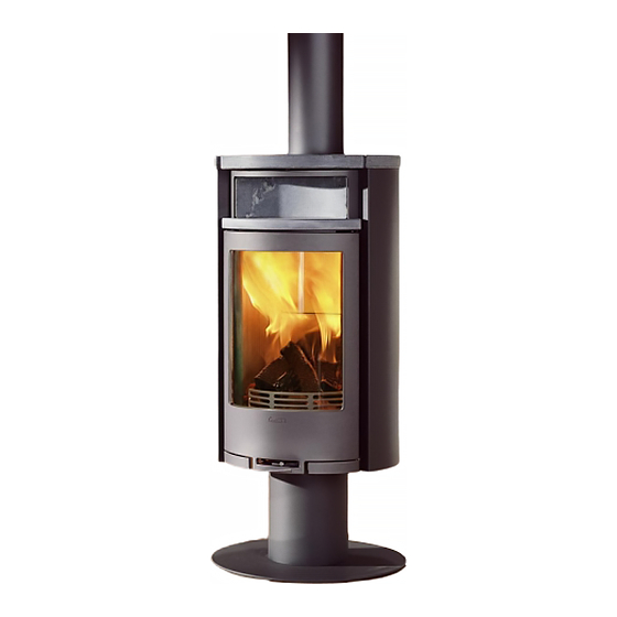
INSTALLATION DISTANCES Installation distances C 685 The minimum distance in front of WHEN INSTALLING TURNTABLE (OPTION) the the stove opening to combustible following installation distances do not apply. parts of the building or interior See the separate turntable installation instruc- Combustible roof decoration must be at least 1 m. -
Page 9: Assembly
ASSEMBLY Installing C 685 The pillar is mounted using four screws. The remaining four screws must also be reinstalled to prevent air leakage into the firebox. - Page 10 ASSEMBLY Clean the side glass thoroughly before installing the side panels. Do not tighten the screws until the insert has been raised from the pallet and is level.
- Page 11 ASSEMBLY Adjust the side panels so that they are against the insert and so that there is an even join against the back plate. Install the convection fascia, warming shelf or baking oven according to the instructions in the section for the relevant accessory on pages 77 to 79.
- Page 12 ASSEMBLY Installing rating plate Position the supplied rating plate on the underside of the pillar. Final inspection of the installation It is extremely important that the installation is inspected by an authorised chimney sweep before the stove is used. Also read the "Lighting instructions" before lighting for the first time.
-
Page 13: Installation Of Oven (Option)
ASSEMBLY Installation of oven (option) Hold the oven door in place on the threaded pin. Hook the top hinge in place and loosely tighten one of the screws. Close the oven door and adjust it so that it aligns horizontally. Then open it carefully and tighten both screws. -
Page 14: Installation Of Metal Warming Shelf (Option)
ASSEMBLY Installation of metal warming shelf (option) Replace the preinstalled adjuster screw in the heating compartment with the longer adjuster screws provided. Place the warming shelf in the heating compartment, use the adjuster screw at the rear edge for horizontal installation. In the side of the heating compartment there is a small gap, this is used to install the rear cover panel. -
Page 15: Installing Convection Fascia (Option)
ASSEMBLY Installing convection fascia (option) Installation of soapstone warming shelf (option) - Page 16 NIBE AB · Box 134 · 285 23 Markaryd · Sweden www.contura.eu Contura reserves the right to change dimensions and procedures described in these instructions at any 811115 IAV SE-EX C685 - 4 time without special notice. The current edition can be 2014-05-06 downloaded from www.contura.eu...
Need help?
Do you have a question about the C 685 and is the answer not in the manual?
Questions and answers