Table of Contents
Advertisement
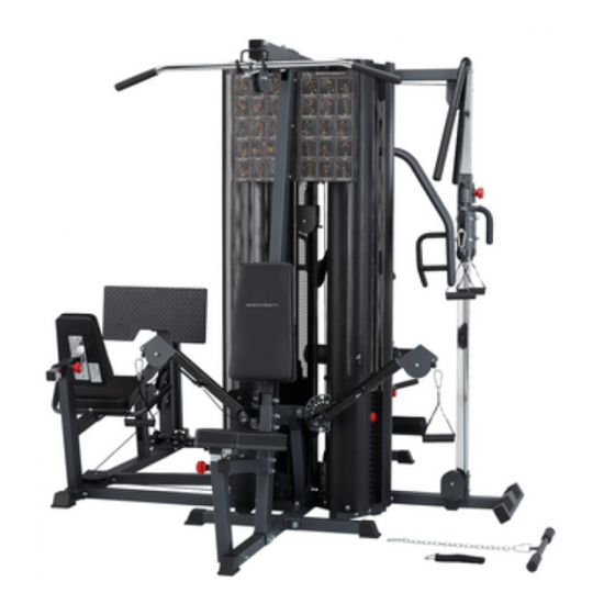
LCS-4 COMMERCIAL MULTI-STATION GYM
ASSEMBLY MANUAL
QUESTION?
As a quality home gym supplier we are committed to your complete satisfaction. If you have
questions, or find missing or damaged parts, we will guarantee your complete satisfaction through
our authorized dealer service centers or our home office customer service department. Please call
your local dealer for assistance or BodyCraft at 800-990-5556 (9:00 AM - 5:00 PM). Our trained
technicians will provide immediate assistance to you, free of charge.
Bodycraft is a division of Recreation Supply Inc.
P.O. BOX 181
Sunbury, OH 43074
429
Advertisement
Table of Contents

Subscribe to Our Youtube Channel
Related Manuals for BodyCraft LCS-4


Summary of Contents for BodyCraft LCS-4
- Page 1 Please call your local dealer for assistance or BodyCraft at 800-990-5556 (9:00 AM - 5:00 PM). Our trained technicians will provide immediate assistance to you, free of charge.
-
Page 2: Before You Begin
7. Make certain all cables are seated within the pulleys before every use. 8. Exercise with care to avoid injury. 9. If unsure about the proper use of the LCS-4 strength training system call your local dealer or our customer service department at... -
Page 3: Exploded View
EXPLODED VIEW... - Page 4 OVERVIEW (3-1) 156 154 88 40 154 153...
- Page 5 OVERVIEW (3-2) 135 148 134 147 135 148 128 147...
- Page 6 OVERVIEW (3-3)
-
Page 7: Parts Chart
PARTS CHART NO. DESCRIPTION QTY. BASE FRAME BASE STABILIZER REAR CABLE ARM UPRIGHT FRONT PRESS ARM UPRIGHT WEIGHT STACK BASE TOP GUIDE ROD RETAINER FRONT STABILIZER CABLE ARM CONNECTOR HAND HOLDER TOP FRAME (bearing pre-installed) LAT BAR HOLDER PRESS ARM SELECTOR GUIDE ROD FRONT SEAT FRAME PRESS ARM... - Page 8 PARTS CHART NO. DESCRIPTION QTY. 50mm SQ. CAP 50mm SQ. PLUG PLASTIC WASHER 50 X 75mm RECT. PLUG 25 X 50mm RECT. PLUG PLASTIC COVER PLASTIC GUIDE ROD HOLDER SHORTER POP PIN(one pcs. pre-assembled) 28.6mm STEEL BUSHING(all pre-assembled) 25.4mm STEEL BUSHING(all pre-assembled) 1/2"...
- Page 9 PARTS CHART NO. DESCRIPTION QTY. 1/2" X 4-1/4" HEX BOLT 1/2" X 3-1/4" HEX BOLT 3/8" X 5-3/4" HEX BOLT 3/8" X 4-3/4" HEX BOLT 3/8" X 3" HEX BOLT 3/8" X 2-3/4" HEX BOLT 3/8" X 2-1/2" HEX BOLT 3/8"...
- Page 10 PARTS CHART DESCRIPTION QTY. BASE STABILIZER LEG PRESS MAIN FRAME LEFT LEG PRESS HANDLE RIGHT LEG PRESS HANDLE LONG LEG PRESS CONNECTOR FRONT LEG PRESS SUPPORT WEIGHT BASE CONNECTOR WEIGHT STACK BASE REAR LEG PRESS SUPPORT FOOT PLATE CONNECTOR FOOT PLATE BACK PAD ADJUSTER LEG PRESS CABLE STEEL TUBE(all pre-assembled)
- Page 11 PARTS CHART DESCRIPTION QTY. WEIGHT STACK BASE TOP GUIDE ROD RETAINER FRONT STABILIZER CABLE HEIGHT ADJUSTER SWIVEL PULLEY BRACKET CHROMED UPRIGHT HAND HOLDER DOUBLE PULLEY BRACKET 90mm PULLEY 3/8" BUSHING 1-1/4" PLUG 6205Z BEARING STEEL SPACER(all pre-assembled) CABLE COLUMN CABLE REMOVABLE END CABLE ARM CABLE HAND GRIP 1"...
-
Page 12: Step 1 Base Frame Assembly
STEP 1 BASE FRAME ASSEMBLY To ease the assembly process, do not tighten bolts until instructed. 1. Attach Base Frame (1) and Front Stabilizer (7) to Base Stabilizer (2), using two 1/2" X 3-1/4" Hex Head Bolts (123), four 1/2" Washers (146) and two 1/2" Nuts (153). Attach five 50mm SQ. -
Page 13: Step 2 Top Frame Assembly
STEP 2 TOP FRAME ASSEMBLY 1. Attach Top Frame - bearing pre-installed (10) to Front & Rear Uprights (3 & 4) using two 1/2" X 4- 1/4" Hex Bolts (122), four 1/2" Washers (146) and two 1/2" Nylon Nuts (153). Attach Lat Bar Holder (11) to Top Frame - bearing pre-installed (10) using two 3/8"... - Page 14 STEP 3 SEATS AND BACK PADS ASSEMBLY 1. Attach Front Seat Frame (14) to Front Upright (4) using two 3/8" X 3" Hex Head Bolts (128), four 3/8" Washers (147) and two 3/8" Nylon Nuts (154). Attach Front Seat Frame (14) to Base Frame (1) using one 3/8"...
- Page 15 STEP 4 BENCH PRESS ASSEMBLY 1. Attach Press Arm Selector (12) to Top Frame - bearing pre-installed (10) by aligning holes and inserting 1" Pivot Axle (33). Lock into place with pre-installed set screw. 2. Attach Press Arm (15) to Press Arm Selector (12) by aligning holes and inserting 1" Pivot Axle (33), 19.95mm Axle (33A).
- Page 16 AB CRUNCH CABLE AB CRUNCH CABLE (108) Route the AB Crunch Cable (108) through (lower) slot and over pulley in Front Upright (4) as shown in Fig. 1 & 2, down and around the pulley mounted on Base Frame (1), up and over lower pulley in Adjustable Pulley Block (30) as shown in Fig.
- Page 17 CABLE ARM CONNECTING CABLE CABLE ARM CONNECTING CABLE (110) Hook Cable Arm Connecting Cable (110) on bracket mounted on Base Frame (1) then route up and over low pulley in Adjustable Pulley Block (30) as shown in Fig. 3, then screw threaded cable end into Single Pulley Block (25).
- Page 18 PRESS ARM CABLE PRESS ARM CABLE (107) Assemble Cables and Pulley simultaneously. Attach steel ball end of the Press Cable (107) to the bracket mounted on Front Upright (4) as shown Fig. 1. Route cable over and around left (as if sitting on seat) side pulley mounted in Press Arm Selector (12), under and around pulley mounted in Front Upright (4), over and around right side pulley in Press Arm Selector (12) as shown Fig.
-
Page 19: Top Cable
TOP CABLE TOP CABLE (109) Route threaded end of Top Cable (109) over pulley mounted to Top Frame (10) as shown in Fig. 1, through slot in Rear Upright (3), over pulley in Top Frame (10), under and around top pulley in Pulley Block (30), as shown in Fig. - Page 20 CABLE ARM CABLE CABLE ARM CABLE (111) Attach Cable Arm Cable (111) on the pulley of Single Pulley Block (25) as shown Fig. 5 Attach pulleys and Pulley Guide Brackets (26) to Cable Arm Assembly (27) as shown in Fig. 3 and Fig. 4. Be certain that, when tightened, the pulley guide brackets do not interfere with cable movement.
- Page 21 LEG PRESS SYSTEM ASSEMBLY 1. Attach Leg Press Weight Base Connector (207) to Base Frame (1), using two 1/2" X 1-1/4" Hex Bolts (169) and two 1/2" Washers (146). Cap two 50mm S.Q. Plugs (64) into Base Connector (207). 2. Attach Long Leg Press Connector (205) into the Weight Base (5), using two 3/8" Washers (147) and two 3/8"...
- Page 22 LEG PRESS CABLE ASSEMBLY bolt end metal ball end LEG PRESS CABLE (213) Screw threaded end of Leg Press Cable (213) into the top of Selector Rod (94) at least 7 threads. Route cable up and over the pulley on Top Guide Rod Retainer (208) as shown Fig 2. then down and under the pulley on Weight Stack Base (207) as shown in Fig.
- Page 23 CABLE COLUMN BASE FRAME ASSEMBLY 1. Attach two 50mm SQ. Plugs (64) to Cable Column Weight Stack Base (301). Attach Cable Column Weight Stack Base (301) to Base Frame (1), using two 1/2" X 1-1/4" Hex Threaded Bolt (169) and two 1/2" Washers (146). 2.
- Page 24 CABLE COLUMN CABLE ball end bolt end CABLE COLUMN CABLE (314) REMOVABLE END (314A) 1. Screw the Double Pulley Bracket (308) into the Top Plate with Selector Rod (94) 10 threads (2cm). 2. Insert the ball end of the Cable Column Cable (314) into the front of the right side Cable Height Adjuster (304) and out of the top.
- Page 25 ASSEMBLE WEIGHT STACK SHROUDS AND POSTER PLATES 1. Attach Weight Stack Shrouds (35) to Weight Stack Bases (5 & 6) and Tops using 5/16" Washers (148) and 5/16" X 1/2" Hex Head Bolts (135). Remember to keep all bolts loose in frame to ensure holes line up easily.
- Page 26 LEG PRESS SHROUD ASSEMBLY 1. Attach Weight Stack Shrouds (35) to Weight Base Connector (207) and Weight Stack Base (208) and Tops using 5/16" Washers (148) and 5/16" X 1/2" Hex Head Bolts (135). Remember to keep all bolts loose in frame to ensure holes line up easily. 2.
- Page 27 CABLE COLUMN WEIGHT STACK SHROUD ASSEMBLY 1. Attach Weight Stack Shrouds (35) to Top Guide Rod Retainer (302) and Weight Stack Base (301) and Tops using 5/16" Washers (148) and 5/16" X 1/2" Hex Head Bolts (135). Remember to keep all bolts loose in frame to ensure holes line up easily.
- Page 28 Guide Rods (13). Enjoy many years of a Fit Lifestyle. Thank you for purchasing the LCS-4 Gym. If You have any questions, please call your local BodyCraft dealer or call our customer service department at 800-990-5556...
Need help?
Do you have a question about the LCS-4 and is the answer not in the manual?
Questions and answers