Table of Contents
Advertisement
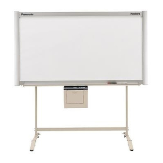
[Stand (option)]
[Wall-mounting (option)]
The unit in this picture is UB-5325.
(Stand and Wall-mounting kit are optional.)
• Please ask your dealer regarding assembly of the electronic board and instruction for wall-mounting.
Before installing this set, please read this manual completely.
Electronic Board
Installation Manual
(for qualified service personnel)
English . . . . . . . . . . . . . . . . .
Français . . . . . . . . . . . . . . . . 23- 44
Deutsch . . . . . . . . . . . . . . . . 45- 66
Español . . . . . . . . . . . . . . . . 67- 88
Italiano . . . . . . . . . . . . . . . . . 89-110
Nederlands. . . . . . . . . . . . . .111-132
Svenska . . . . . . . . . . . . . . . .133-154
中 文 . . . . . . . . . . . . . . . . . .155-176
Русский . . . . . . . . . . . . . . . .177-198
UB-5325
Model No.
UB-5825
1- 22
Advertisement
Table of Contents


Need help?
Do you have a question about the UB-5325 and is the answer not in the manual?
Questions and answers