Travis Industries 36 CF Nstallation Manual
Hide thumbs
Also See for 36 CF:
- Installation manual (48 pages) ,
- Operation & maintenance manual (20 pages) ,
- Quick start manual (4 pages)
Table of Contents
Advertisement
WARNING: If the information in these instructions is not followed exactly, a fire or
explosion may result causing property damage, personal injury or loss of life.
-
Do not store or use gasoline or other flammable vapors and liquids in the vicinity of this or
any other appliance.
WHAT TO DO IF YOU SMELL GAS
• Do not try to light any appliance.
• Do not touch any electrical switch; do not use any phone in your building.
• Immediately call gas supplier from a neighbor's phone. Follow the gas supplier's
instructions.
• If you cannot reach your gas supplier, call the fire department.
-
Installation and service must be performed by a qualified installer, service agency or the
gas supplier.
This appliance may be installed as an OEM installation in a manufactured (mobile) home and must be
installed in accordance with the manufacturer's instructions and the manufactured home construction
and safety standard, Title 24 CFR, Part 3280.
This appliance is only for use with the type(s) of gas indicated on the rating plate. A conversion kit is
supplied with the appliance.
Installation Manual
Installer:
After installation give this manual to the home-
owner and explain operation of this heater.
Copyright 2007, T.I.
$10.00
100-01170
36 CF
Fireplace
Tested and Listed by
OMNI-Test Laboratories, Inc.
Beaverton, Oregon
Report # 028-S-57-5
ANSI Z21.88b-2003
• Built-In Direct Vent Fireplace
• Natural Gas or Propane
•
Residential or Mobile Home
•
Bedroom Approved
4800 Harbour Pointe Blvd. SW
4060421
Mukilteo, WA 98275
Advertisement
Table of Contents

Related Manuals for Travis Industries 36 CF


Summary of Contents for Travis Industries 36 CF
- Page 1 36 CF Fireplace Tested and Listed by OMNI-Test Laboratories, Inc. Beaverton, Oregon Report # 028-S-57-5 ANSI Z21.88b-2003 • Built-In Direct Vent Fireplace • Natural Gas or Propane • Residential or Mobile Home • Bedroom Approved WARNING: If the information in these instructions is not followed exactly, a fire or explosion may result causing property damage, personal injury or loss of life.
-
Page 2: Overview
This manual details the installation requirements for the 36 CF fireplace. For operating and maintenance instructions, refer to the 36 CF Owner's Manual (part # 100-01176). Listing Details This appliance was listed by OMNI Test Labs to ANSI Z21.88 - report # 028-S-57-5. The listing label is attached to the appliance near the gas control valve. -
Page 3: Table Of Contents
Nailing Brackets ............15 Index Gas Line Requirements..........16 Fuel ..............16 Index..............52 Gas Line Connection ..........16 Gas Inlet Pressure ..........16 Battery Pack – Wireless Wall Switch Installation ... 17 Battery Installation ..........20 Remote Synchronization..........21 © Travis Industries 4060623 100-01170... -
Page 4: Safety Precautions
All other work must be done by a trained technician. Don't modify or replace orifices. • The viewing glass should be opened only for lighting the pilot or conducting service. • Any safety screen or guard removed for servicing must be replaced prior to operating the heater. Travis Industries 4060623 100-01170... - Page 5 The gas main shutoff valve is usually next to the gas meter or propane tank and requires a wrench to shut off. • Travis Industries, Inc. grants no warranty, implied or stated, for the installation or maintenance of your heater, and assumes no responsibility of any consequential damage(s).
-
Page 6: Features And Specifications
8.625" Outside Diameter 27" *** 12.25"* 42.5" ** 56" ** 41" NOTE: 2" Clearance to the Back of the Fireplace 36 CF R 32.25" ** 36 CF A 32.25" ** 31.75" ** Base of Fireplace NOTE: 4" Clearance to 38.25"... -
Page 7: Installation
• Firebacks –Arched (96100166) - Rectangular (96100172) available from Travis Industries • 36 CF Direct Vent (available only from Travis Industries – see page 23 for part numbers) • Gas Line Equipment (shutoff valve, pipe, etc.) •... -
Page 8: Recommended Installation Procedure
4. Install the vent, gas line and control panel. 5. Install the framing above the header. 6. Install the non-combustible facing. 7. Install the hearth (if applicable). 8. Install the facing. 9. Install the mantel (if applicable). 10. Finalize the installation (see page 37). Travis Industries 4060623 100-01170... -
Page 9: Massachusetts Requirements
Gas Line Requirements See “ ” on page16 for additional Massachusetts requirements. © Travis Industries 4060623 100-01170... -
Page 10: Preparing The Fireplace Stand-Offs
Secure the stand-off with two screws removed earlier. Repeat steps "a", "b", and "c" for the opposite side. Figure 4 Travis Industries 4060623 100-01170... - Page 11 The notch in the side brace slides over this screw. Rotate the header bracket up Un-fold the side of the header standoff until it is flat. Repeat steps "b" and "c" for the opposite side. Figure 5 © Travis Industries 4060623 100-01170...
-
Page 12: Fireplace Placement Requirements
The fireplace (and hearth, if desired) may be placed on a platform designed to support the fireplace 250 Lbs.) and vent. Min. 82” Fireplace Enclosure Height Platform (with cement board) Optional Raised Hearth (see “Hearth Requirements” for details) Figure 6 Travis Industries 4060623 100-01170... -
Page 13: Minimum Framing Dimensions
Minimum 82” Fireplace 14” Min. Enclosure Height NOTE: On LP 3.5” Max. installations with minimum vertical rise, minimum enclosure height is 96”. 25” 56.75” * 50” * Includes the 1/2” cement board. Figure 7 © Travis Industries 4060623 100-01170... -
Page 14: Framing Dimensions - Corner Installations
(for qualified installers only) Framing Dimensions - Corner Installations A typical 45° installation uses the framing dimensions shown in the illustration below (NOTE: all clearances still apply). Minimum 2" Clearance 19.25" (approximate) 54.5" (approximate) Figure 8 Travis Industries 4060623 100-01170... -
Page 15: Nailing Brackets
Installation (for qualified installers only) Nailing Brackets Use screws or nails to secure the fireplace to the framing with the six nailing brackets. Figure 9 © Travis Industries 4060623 100-01170... -
Page 16: Gas Line Requirements
The supply regulator (the regulator that attaches directly to the residence inlet or to the propane tank) should supply gas at the suggested input pressure listed above. Contact the local gas supplier if the regulator is at an improper pressure. Travis Industries 4060623 100-01170... -
Page 17: Battery Pack - Wireless Wall Switch Installation
Gas Control Valve Battery Pack Wires (4) Receiver Module * The wireless wall switch may be located at a separate location. An additional cover plate would be required for the battery back junction box. Figure 11 © Travis Industries 4060623 100-01170... - Page 18 Red and Black/Red wires (w quick connects) Gas Control Valve Used Make sure continuous pilot is set to "OFF" and remote is set to "REMOTE". Main Burner Control Wires White Green Orange White Pilot Flame Control Wires Figure 12 Travis Industries 4060623 100-01170...
- Page 19 Cover Plate are replaced. (snaps into place) Wireless Wall Switch (includes two "CR2032" 3V batteries) Secure to the junction box with the two included screws. Figure 14 © Travis Industries 4060623 100-01170...
-
Page 20: Battery Installation
(4) AA batteries. Wireless Wall Switch The Remote requires two (2) AAA batteries (included) Cover Plate (snaps into place) Back of Remote The Wall Switch requires two (2) CR2032 3V batteries (included) CR2032 CR2032 Figure 15 Travis Industries 4060623 100-01170... -
Page 21: Remote Synchronization
* If either the remote or wall switch do not work properly, follow the steps to Synchronize the remote and wall switch on the following page. Figure 16 © Travis Industries 4060623 100-01170... -
Page 22: Travis Industries
To do this, hold down the LEARN button on the reciever for approximately 10 seconds until the receiver beeps 3 times. This indicates the receiver has been re-set and can be synchronized using the instructions above. Travis Industries 4060623 100-01170... -
Page 23: Vent Requirements
• Failure to adjust the air shutter properly may lead to improper combustion which can create a safety hazard. Consult your dealer or installer if you suspect an improperly adjusted air shutter. © Travis Industries 4060623 100-01170... -
Page 24: Vent Clearances
If it does not, apply high temperature sealant to the joints of the affected sections. • Horizontal sections require a 1/4" rise every 12" of travel • Horizontal sections require non-combustible support every three feet (e.g.: plumbing tape) Travis Industries 4060623 100-01170... -
Page 25: Approved Vent Configurations
(open - stock position) # 1 (closed) #3 Figure 17 Intake Restrictor Adjustment The intake restrictor must be removed for certain vent configurations. After removal, replace the 2 screws. Figure 18 © Travis Industries 4060623 100-01170... -
Page 26: Horizontal Termination (1 90° Elbow)
10 feet 5 feet 5 feet INSTALLATION NOTE: LP installations require a minimum 3' rise directly off the fireplace. NG installations requires a minimum 2' rise directly off the fireplace. 0 feet 0 feet Figure 19 Travis Industries 4060623 100-01170... -
Page 27: Horizontal Termination (3 90° Elbows)
10 feet 5 feet 5 feet INSTALLATION NOTE: LP installations require a minimum 3' rise directly off the fireplace. NG installations requires a minimum 2' rise directly off the fireplace. 0 feet 0 feet Figure 20 © Travis Industries 4060623 100-01170... -
Page 28: Vertical Termination (0, 2, Or 4 45° Elbows)
Exhaust Restrictor # 2 Intake Restrictor Removed 20 feet 20 feet Exhaust Restrictor # 1 (stock) Intake Restrictor Removed 15 feet 15 feet 10 feet 10 feet (min.) (min.) 5 feet 5 feet 0 feet 0 feet Figure 21 Travis Industries 4060623 100-01170... -
Page 29: Vertical Termination (2 90° Elbows)
Intake Restrictor Removed 20 feet 20 feet 15 feet 15 feet Exhaust Restrictor # 1 (stock) Intake Restrictor Removed 10 feet 10 feet (min.) (min.) 5 feet 5 feet 0 feet 0 feet Figure 22 © Travis Industries 4060623 100-01170... -
Page 30: Termination Requirements
NOTE: Measure clearances to the nearest edge of the exhaust hood. • Use the vinyl siding standoff when installing on an exterior with vinyl siding. • Vent termination must not be located where it will become plugged by snow or other material Travis Industries 4060623 100-01170... -
Page 31: Hearth Requirements
Fireplace Hearth Material over 1” Thick base of the fireplace (it must fit under the glass frame). (granite, concrete, etc.) 1” Cement Board Fireplace Marble Plywood (OSB, etc.) 1” Framing Sub-Floor Cement Board Figure 23 © Travis Industries 4060623 100-01170... -
Page 32: Hearth Requirements - Recessed Hearth
Framing make the platform a suitable height for un-cut tile. For example, if using 12” tile, make the platform 11” tall (10” section Carpet Sub-Floor of framing + 1/2” plywood + 1/2” cement board). Figure 24 Travis Industries 4060623 100-01170... -
Page 33: Facing Requirements
Flanges are provided on the fireplace for the screws to attach to. Figure 25 Typical Cement Board Dimensions 36 CF R 36 CF A Minimum 50” (typically 51.5”) Minimum 50” (typically 51.5”) Minimum 56” * Minimum 56” * (typically 56.5”... -
Page 34: Non-Combustible Facing
10-1/2” side wall clearances. • The maximum depth for non-combustible facing is 6” (includes the cement board). Cement Board Combustible Material Max. 3/4” 12” Min. Non-Combustible Facing (tile, rock, marble, etc.) Fireplace Glass Frame Figure 27 Travis Industries 4060623 100-01170... - Page 35 Installation (for qualified installers only) Facing Examples Drywall TOP VIEW Framing Fireplace Drywall Cement Board 12” Tile Drywall TOP VIEW Framing Fireplace Drywall Cement Board Masonry (e.g. stone, brick) Figure 28 © Travis Industries 4060623 100-01170...
-
Page 36: Mantel Requirements
(10.5” from the glass frame). If they protrude 3/4” or less, they must meet the facing clearance (6” from the glass frame). Non-combustible mantel columns do not have a minimum clearance. Base of the Fireplace Figure 29 Travis Industries 4060623 100-01170... - Page 37 5. Replace the glass. Start the pilot. 6. Start the main burner. Leak test all gas joints again (the gas control valve and connections are located on the exterior of the fireplace on the left side. © Travis Industries 4060623 100-01170...
-
Page 38: Finalizing The Installation
Travis dealer for a remedy. 9. Give this manual to the home owner for future reference and fully explain operation of this heater. For comprehensive operating and maintenance instructions, refer to the Owner's Manual (part # 100-01168). Travis Industries 4060623 100-01170... -
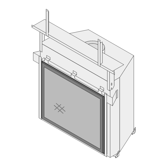
Page 39: Glass Frame Removal And Installation
Use the door latch tool to pull the latch forward and away from the glass frame. The glass frame is held in place with four latches. REPLACING THE GLASS Slide the glass into place and secure the four latches. Figure 30 © Travis Industries 4060623 100-01170... -
Page 40: Fireback Installation
While holding the rear firebacks in place, slide the side firebacks between the burner and side wall of the firebox. The side firebacks hold the back firebacks in place. Figure 31 Restore the fireplace to the correct configuration. Travis Industries 4060623 100-01170... -
Page 41: Log Set Installation
Overview Below is a picture detailing log placement for this fireplace. Follow the directions on the following pages to place the logs correctly. Right Rear Left Upper Log Left Lower Center Log Upper Right Log © Travis Industries 4060623 100-01170... - Page 42 Finalizing the Installation (for qualified installers only) Center Log Place the center log as shown below. The rear log contacts the side and back fireback. Travis Industries 4060623 100-01170...
- Page 43 Place the right rear log as shown below. The right rear log has a hole that inserts over the pin on the center log. The right rear log has a flat portion that rests on the grate. © Travis Industries 4060623 100-01170...
- Page 44 Place the upper left log as shown below. The upper left log has a hole that inserts over the pin on the center log. The upper left log has a notch that fits over the grate. Travis Industries 4060623 100-01170...
- Page 45 The right rear log has a flat portion that the upper right log rests against. The upper right log has a notch that fits over the grate. Note how the upper right log is positioned. © Travis Industries 4060623 100-01170...
-
Page 46: Ember Placement
The wool glows best WARNING: If the rock wool is too thick or placed so it when very thin and porous. obstructs the flow of gas, sooting will occur. Travis Industries 4060623 100-01170... -
Page 47: Lp Conversion Instructions
Remove the two screws that secure the burner to the firebox floor. Slide the burner to the right and up to remove the burner from the firebox. Figure 32 © Travis Industries 4060623 100-01170... - Page 48 Rear correct orifices. Burner Orifice Front Burner Orifice Look here for the orifice identification Front 1.8mm Rear 15/16” Screw each LP orifice in so the orifice protrudes 15/16” (indicating full insertion). Figure 33 Travis Industries 4060623 100-01170...
- Page 49 The burner tray is held are found on the back in place with 7 screws. side of this plate. Remove the burner tray and place it on the firebox floor. Figure 35 © Travis Industries 4060623 100-01170...
- Page 50 Make the gas line connection, bleed the gas line (if applicable), start the heater and thoroughly leak-test all gas connections and the gas control valve (see Gas Line Requirements on page 16 for details). Check the pilot and adjust if necessary. Travis Industries 4060623 100-01170...
- Page 51 Finalizing the Installation (for qualified installers only) © Travis Industries 4060623 100-01170...
-
Page 52: Index
Vent Clearances..........24 Hearth Requirements – Recessed Hearth ....32 Vent Installation ..........24 Hearth Requirements ..........31 Vent Requirements ..........23 Horizontal Termination (1 90° Elbow) ......26 Vertical Termination (0, 2, or 4 45° Elbows).....28 Vertical Termination (2 90° Elbows)......29 Travis Industries 4060623 100-01170...
Need help?
Do you have a question about the 36 CF and is the answer not in the manual?
Questions and answers