
Related Manuals for Mitsubishi S6S-Y3T61HF


Summary of Contents for Mitsubishi S6S-Y3T61HF
- Page 1 SERVICE MANUAL for HYUNDAI HEAVY INDUSTRIES CO.,LTD. August 2008 99616-25000 99616-25000 Pub. No. Printed in Japan Pub. No.
- Page 3 INTRODUCTION This service manual describes the specifications, maintenance and service procedures for Mitsubishi diesel engines. To maintain the performance of the engine for many years and to ensure safe operation, it is important to use the engine correctly and conduct regular inspection and maintenance, and also to take necessary measures which involves the disassembly, inspection, repair and reassembly of the engine and engine parts.
-
Page 5: How To Use This Manual
Mitsubishi Diesel Engine (standard model for land use). A short summary describing the content of each Group is given in the General Contents page, and there is also a detailed table of contents at the beginning of each Group. - Page 6 INTRODUCTION Terms used in this manual Nominal means the rated (design) size or magnitude of a part to be measured. Standard means the quantitative requirement for dimension of a part, clearance between parts and performance. This is given in a form of tolerance.
-
Page 7: Fire And Explosion
INTRODUCTION Safety Cautions WARNING Fire and explosion Keep flames away Care about fuel, oil and exhaust gas leakage Store fuel and engine oil in a well If any fuel, oil or exhaust gas leakage is found, immedi- ventilated designated area. ately take corrective measures to stop it. - Page 8 INTRODUCTION WARNING Stay clear of all rotating and moving parts Install protective covers on rotating parts Lockout and tagout Make sure the protective covers for Be sure to lockout and tagout before starting inspection engine rotating parts are properly and maintenance. installed as intended.
- Page 9 INTRODUCTION WARNING WARNING Be careful of burns Be careful of exhaust fume poi- soning Do not touch the engine during or immedi- ately after operation Operate engine in well-ventilated area Do not touch the engine during or If the engine is installed in an en- immediately after operation...
- Page 10 Such a way of disposal is strictly prohibited by laws and regulations. Dispose of waste oil, coolant and other environmentally hazardous waste in accordance with the applicable law and regulations, or consult a Mitsubishi dealer.
- Page 11 INTRODUCTION CAUTION CAUTION Service battery When abnormality occurs Handle the battery correctly Stop overheated engine after cooling run • Never use flames or allow sparks Even if the engine comes to overheat, do not stop the to generate near the battery. The engine immediately.
- Page 12 INTRODUCTION CAUTION Other cautions Modification of engine prohibited Warming-up operation Unauthorized modification of the engine will void the After starting the engine, run the engine at low idling manufacturer’s warranty. speeds for 5 to 10 minutes for warming-up. Start the Modification of the engine may not only cause engine work after this operation is completed.
- Page 13 INTRODUCTION Maintenance of air cleaner or pre-cleaner Avoidance of prolonged time of starter oper- The major cause of abnormal wear on engine parts is ation dust entering with intake air. Worn parts produce many Do not operate the starter for more than 10 seconds at problems such as an increase of oil consumption, de- a time even if the engine does not start.
- Page 14 INTRODUCTION CAUTION About warning labels Maintenance of warning labels Make sure all warning/caution labels are legible. Clean or replace the warning/caution labels when the description and/or illustration are not clear to read. For cleaning the warning/caution labels, use a cloth, water and soap. Do not use cleaning solvents, gasoline or other chemicals to prevent the letters from getting blurred or the adhesion from being weakened.
-
Page 15: Table Of Contents
GENERAL CONTENTS Group Name Contents Group No. External view System flow diagrams General Engine serial number location Main specifications Tips on disassembling and reassembling Maintenance service data Service data Tightening torque table Regarding submission of parts for EPA exhaust gas regulation Service tools Special tool Determining overhaul timing... - Page 17 GENERAL 1. External view........1-2 2. System flow diagrams .....1-4 2.1 Fuel system - flow diagram ...... 1-4 2.2 Lubrication system - flow diagram ... 1-4 2.3 Cooling system - flow diagram....1-5 2.4 Inlet and exhaust system - flow diagram.. 1-5 3.
-
Page 18: External View
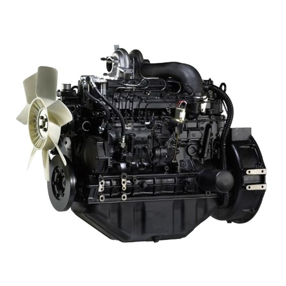
GENERAL 1. External view S6S-Y3T61HF Fuel filter Oil cooler Water pump (Coolant inlet) Coolant drain plug Flywheel Front Rear Magnet valve (Stop solenoid) Oil filter Fuei injection pump Relief valve Oil drain plug Engine left view S6S-Y3T61HF Oil level gauge... - Page 19 GENERAL S6S-Y3T62HF Oil cooler Magnet valve (Stop solenoid) Oil level gauge Fuel filter Water pump Coolant drain plug (Coolant inlet) Flywheel Front Rear Fuei injection pump Oil filter Relief valve Oil drain plug Engine left view S6S-Y3T62HF Turbocharger Air inlet Oil filler (Exhaust outlet) Oil filler...
-
Page 20: System Flow Diagrams
2.2 Lubrication system - flow diagram Piston Oil jet Turbocharger Crankshaft Pushrod Valve mechanism Tappet Oil cooler Camshaft Main gallery Idler gear Relief valve Oil filter Side PTO (Drive gear) [S6S-Y3T61HF] Oil pump Oil pan Oil strainer Safety valve Lubrication system - flow diagram... -
Page 21: Cooling System - Flow Diagram
GENERAL 2.3 Cooling system - flow diagram Thermostat Cooling outlet Oil cooler Cylinder head Bypass hose Water jacket Water pump Cooling inlet Cooling system - flow diagram 2.4 Inlet and exhaust system - flow diagram Inlet Turbocharger Exhaust Inlet Exhaust Blow-by gas Discharge Exhaust manifold... -
Page 22: Engine Serial Number Location
GENERAL 3. Engine serial number location The engine serial number is stamped on the right side of cylinder block. Engine serial number Engine serial number location... -
Page 23: Main Specifications
GENERAL 4. Main specifications Table 1-1 Main specifications (1 / 3) Engine model S6S-Y3T61HF S6S-Y3T62HF Type Water cooled, 4 cycle diesel engine, turbocharged No. of cylinders - arrangement 6 cylinder in-line Combustion system Swirl chamber type Valve mechanism Overhead Cylinder bore × stroke 94 ×... - Page 24 GENERAL Table 1-1 Main specifications (2 / 3) Engine model S6S-Y3T61HF S6S-Y3T62HF Forced circulation type Lubricating method (pressure feed by oil pump) Standard Class CF-4 oil SAE No.30 (API service classification) Engine oil Engine total: approx. 16.5 L [4.36 U.S. gal.] Engine oil capacity (approx.
- Page 25 GENERAL Table 1-1 Main specifications (3 / 3) Engine model S6S-Y3T61HF S6S-Y3T62HF Voltage - polarity 24V - negative (-) ground Model number M008T60373 Pinion meshing type Pinion shift Starter Output 24 V - 5 kW Ring gear and pinion ratio...
-
Page 26: Tips On Disassembling And Reassembling
5. Tips on disassembling and reassem- bling This service manual specifies the recommended procedures to be followed when servicing Mitsubishi engines. The manual also specifies the special tools that are required for the work, and the basic safety precautions to follow when working. - Page 27 SERVICE DATA 1. Maintenance service data ....2-2 1.1 General ............ 2-2 1.2 Basic engine ..........2-3 1.3 Fuel system..........2-6 1.4 Lubrication system ........2-6 1.5 Cooling system ........2-7 1.6 Inlet and exhaust system ......2-7 1.7 Electrical system ........2-8 2.
-
Page 28: Maintenance Service Data
SERVICE DATA 1. Maintenance service data 1.1 General Table 2-1 Maintenance service data table - General Unit: mm [in.] Inspection point Nominal Standard Limit Remark Maximum rotation speed (No-load) 2570 ± 50 min Minimum rotation speed (No-load) 820 ± 25 min When oil and water 3.2 MPa 2.8 MPa... -
Page 29: Basic Engine
SERVICE DATA 1.2 Basic engine Table 2-2 Maintenance service data table - Basic engine (1 / 4) Unit: mm [in.] Inspection point Nominal Standard Limit Remark ø 19 19.010 to 19.030 Rocker bushing inside diameter [0.75] [0.7484 to 0.7492] ø 19 18.980 to 19.000 Rocker Rocker shaft outside diameter... -
Page 30: Service Data
SERVICE DATA Table 2-2 Maintenance service data table - Basic engine (2 / 4) Unit: mm [in.] Inspection point Nominal Standard Limit Remark 93.955 to 93.985 93.770 [3.6990 to 3.7002] [3.6917] Outside diameter ø 94 94.205 to 94.235 94.020 0.25 [0.0098]/OS (at piston skirt) [3.70] [3.7089 to 3.7100]... - Page 31 SERVICE DATA Table 2-2 Maintenance service data table - Basic engine (3 / 4) Unit: mm [in.] Inspection point Nominal Standard Limit Remark 0.04 0.10 Runout [0.0016] or less [0.0039] 6.682 6.382 to 6.782 6.182 Inlet [0.2631] [0.2513 to 0.2670] [0.2434] Cam lift 6.722...
-
Page 32: Fuel System
SERVICE DATA Table 2-2 Maintenance service data table - Basic engine (4 / 4) Unit: mm [in.] Inspection point Nominal Standard Limit Remark Replace bearings before 0.200 limit is reached. Regrind [0.0079] crank journal and use next Clearance between main bearing and crank- 0.050 to 0.110 crank journal Main bearing... -
Page 33: Cooling System
SERVICE DATA 1.5 Cooling system Table 2-5 Maintenance service data table - Cooling system Unit: mm [in.] Inspection point Nominal Standard Limit Remark Temperature at which valve starts 76.5 ± 1.5°C opening [170 ± 3.5°F] Thermostat Temperature at which valve lift is 90 ±... -
Page 34: Electrical System
SERVICE DATA 1.7 Electrical system Table 2-7 Maintenance service data table - Electrical system Unit: mm [in.] Inspection point Nominal Standard Limit Remark ø 32 31.4 Outside diameter [1.26] [1.236] 0.05 0.10 Commutator Runout [0.0020] or less [0.0039] 0.4 to 0.6 Undercut depth [0.016 to 0.024] [0.008]... -
Page 35: Tightening Torque Table
SERVICE DATA 2. Tightening torque table 2.1 Major bolt tightening torque 2.1.1 Basic engine Table 2-8 Tightening torque table - Basic engine Threads Torque Description Dia × Pitch Remark N·m kgf·m lbf·ft (mm) Cylinder head 12 × 1.75 118 ± 5 12 ±... -
Page 36: Lubrication System
SERVICE DATA 2.1.3 Lubrication system Table 2-10 Tightening torque table - Lubrication system Threads Torque Description Dia × Pitch Remark N·m kgf·m lbf·ft (mm) Oil pan 8 × 1.25 11.3 ± 1.5 1.15 ± 0.15 8.3 ± 1.1 Oil pan drain plug 20 ×... -
Page 37: Standard Bolt And Nut Tightening Torque
SERVICE DATA 2.2 Standard bolt and nut tightening torque 2.2.1 Metric automobile screw thread Table 2-14 Metric automobile screw thread Threads Width Strength classification Dia × Pitch across flats 10.9 (mm) (mm) [in.] N·m kgf·m lbf·ft N·m kgf·m lbf·ft N·m kgf·m lbf·ft M6 ×... -
Page 38: Regarding Submission Of Parts For Epa Exhaust Gas Regulation
New parts may be updated due to improvement. Fuel and exhaust system repairs should only be con- ducted by an authorized Mitsubishi forklift truck dealer. Tampering or adjusting the fuel system components will void the warranty and could be in violation of the EPA regulations. -
Page 39: Service Tools
SERVICE TOOLS 1. Special tool........3-2... -
Page 40: Special Tool
SERVICE TOOLS 1. Special tool Table 3-1 Special tool list (1 / 3) Tool name Part No. Shape Engine compression pressure measuring Compression gauge 33391-02100 0 to 7 MPa {0 to 71.4 kgf/cm²} [0 to 1015.54 psi] Engine compression pressure Gauge adapter 30691-21100 measuring... - Page 41 SERVICE TOOLS Table 3-1 Special tool list (2 / 3) Tool name Part No. Shape Camshaft, thrust plate and Socket 34491-00300 rocker bracket installation Valve guide installer 32A91-00100 Valve guide installation Camshaft bushing Camshaft bushing installer set 30691-00010 removal/installation Idler bushing Idler bushing installer 30091-07300 removal/installation...
- Page 42 SERVICE TOOLS Table 3-1 Special tool list (3 / 3) Tool name Part No. Shape Oil seal sleeve installer Oil seal sleeve installation of 30691-13010 guide set crankshaft rear side Piston installer 34491-00200 Piston installation Oil pump bushing installer 32A91-00400 Oil pump bushing installation Ring pliers 49160-90101...
-
Page 43: Determination Of Overhaul
DETERMINATION OF OVERHAUL 1. Determining overhaul timing ...4-2 2. Testing compression pressure ..4-3... - Page 44 DETERMINATION OF OVERHAUL 1. Determining overhaul timing In most cases, the engine should be overhauled when the compression pressure of the engine becomes low. An increase in engine oil consumption and blow-by gas are also considered to evaluate the engine condition. Besides, such symptoms as a decrease in output, increase in fuel consumption, decrease in oil pressure, difficulty of engine starting and increase in noise are also considered for judging the overhaul timing, although those symptoms are often affected by other causes, and are not always effective to judge the overhaul timing.
-
Page 45: Testing Compression Pressure
DETERMINATION OF OVERHAUL 2. Testing compression pressure CAUTION (a) Be sure to measure the compression pressure for all the cylinders. It is not a good practice to mea- sure the compression pressure for only one cylin- Compression Gauge adapter der, and presume the compression for the gauge P/N:30691-21100 P/N:33391-02100... - Page 47 DISASSEMBLY OF BASIC ENGINE 1. Disassembling and inspecting cylinder head and valve mechanism ....5-2 1.1 Removing rocker shaft assembly..... 5-3 1.2 Disassembling rocker shaft assembly..5-3 1.3 Removing cylinder head bolt....5-3 1.4 Removing cylinder head assembly ..5-4 1.5 Removing valve and valve spring .... 5-4 1.6 Removing valve stem seal .......
-
Page 48: Disassembling And Inspecting Cylinder Head And Valve Mechanism
DISASSEMBLY OF BASIC ENGINE 1. Disassembling and inspecting cylinder head and valve mechanism Replace Wear Damaged threads, Worn valve cap contact worn rod contact surface surface, clogged oil holes Wear, clogged oil holes Wear at both ends, deflection Crack, damage, carbon deposits, Fatigue, damage water scale adhesion Replace... -
Page 49: Removing Rocker Shaft Assembly
DISASSEMBLY OF BASIC ENGINE 1.1 Removing rocker shaft assembly CAUTION Adjusting screw Always loosen shorter bolts first. Failing to do so may Rocker bracket bolt cause the damage to the rocker shaft bracket. (1) Loosen the rocker arm adjusting screws by rotating about one turn. -
Page 50: Removing Cylinder Head Assembly
DISASSEMBLY OF BASIC ENGINE 1.4 Removing cylinder head assembly CAUTION Cylinder head When removing the cylinder head gasket, be careful not to damage the cylinder head or crankcase surface with tools such as a screwdriver. (1) Remove the cylinder head bolt. (2) Remove the cylinder head assembly by lifting it up. -
Page 51: Disassembling And Inspecting Flywheel
DISASSEMBLY OF BASIC ENGINE 2. Disassembling and inspecting flywheel Replace Crack, abnormality of knock hole Lip wear, damage or aging Crack, knock hole defect, gear damage Damaged threads Disassembling and inspecting flywheel Disassembling sequence 1 Flywheel 2 Rear plate 3 Oil seal 4 Gasket... -
Page 52: Removing Flywheel
DISASSEMBLY OF BASIC ENGINE 2.1 Removing flywheel CAUTION (a) Be careful not to cut yourself with the ring gear when pulling out the flywheel. Be careful not to drop or hit the flywheel when removing. (b) The person who holds the pulley must be very careful to assure safety by communicating with the person who is removing the flywheel. -
Page 53: Disassembling And Inspecting Damper, Gear Case, Timing Gear And Camshaft
DISASSEMBLY OF BASIC ENGINE 3. Disassembling and inspecting damper, gear case, timing gear and camshaft S6S-Y3T61HF Wear, damage Flaking, Replace Clogging of oil uneven contact, hole, wear damage, key groove Wear, damage defect, abnormal wear bushings Clogged oil hole Wear... - Page 54 DISASSEMBLY OF BASIC ENGINE S6S-Y3T62HF Wear, damage Flaking, uneven contact, Replace Clogging of oil damage, hole, wear key groove defect, abnormal wear Wear, damage bushings Clogged oil hole Wear Replace Replace Flaking, uneven contact, damage, key groove defect, Replace abnormal wear Lip wear, bushings damage or aging...
-
Page 55: Removing Crankshaft Pulley And Damper
(2) Remove the crankshaft pulley and damper. Removing damper Prevent crankshaft 回り止めをする from rotating Guide bolt Crankshaft pulley (M12×1.25mm) (Rear) (Front) Removing crankshaft pulley 3.2 Removing cover S6S-Y3T62HF Unscrew the cover mounting bolts, and remove the cover. Cover Removing cover S6S-Y3T61HF Bearing case Cover Removing cover... -
Page 56: Removing Timing Gear Case
Note: Bolts have different lengths. Pay attention to the positions of bolts to ensure correct reassembling. Gasket Timing gear case Removing timing gear case S6S-Y3T61HF Timing gear case Gasket Removing timing gear case 3.4 Measuring timing gear backlash Measure the backlash of the timing gears by using one of the following two methods;... -
Page 57: Measuring Idler Gear And Camshaft Gear End Play
DISASSEMBLY OF BASIC ENGINE 3.5 Measuring idler gear and camshaft gear end play Using a feeler gauge or dial gauge, measure the end play of idler gear and camshaft gear. If the measured value exceeds the limit, replace the thrust plate with a new one. -
Page 58: Removing Oil Pump Gear
(1) Remove the thrust plate bolt. (2) Remove the idler gear while turning the gear. Idler gear Removing idler gear 3.11 Removing PTO drive gear S6S-Y3T61HF Remove the PTO drive gear tapping lightly with plastic hammer. Removing PTO drive gear 3.12 Removing camshaft... -
Page 59: Separating Camshaft Gear
DISASSEMBLY OF BASIC ENGINE 3.13 Separating camshaft gear Using hydraulic press, remove the camshaft gear and thrust Punch out with hydraulic press plate from the camshaft. Note: Do not remove the camshaft gear from the camshaft Camshaft gear unless the camshaft gear or the thrust plate is defective. -
Page 60: Disassembling And Inspecting Piston, Connecting Rod, Crankshaft And Crankcase
DISASSEMBLY OF BASIC ENGINE 4. Disassembling and inspecting piston, connecting rod, crankshaft and crankcase Wear, damage Surface scratches, cracks, Fatigue damage, wear, carbon deposits Wear Cracks, Wear clogged oil holes Wear, clogged oil holes Damaged threads Serration for cracks, wear Scratches on inside and outside surfaces, seizing, flaking, wear... -
Page 61: Removing Connecting Rod Cap
DISASSEMBLY OF BASIC ENGINE 4.1 Removing connecting rod cap (1) Lay the engine on its side. (2) Mark the cylinder number on the connecting rod and connecting rod cap so that their combination is not changed when reassembling. (3) Remove the connecting rod caps. Note: Mark the cylinder No. -
Page 62: Removing Piston Ring
DISASSEMBLY OF BASIC ENGINE 4.4 Removing piston ring Remove the piston rings using piston ring pliers. Piston ring pliers P/N:31391-12900 Removing piston ring 4.5 Removing piston pin and piston (1) Using ring pliers, remove the snap ring. (2) Using a wooden block and mallet, remove the piston pin, and separate the piston from the connecting rod. -
Page 63: Removing Crankshaft
DISASSEMBLY OF BASIC ENGINE 4.7 Removing crankshaft CAUTION Be careful not to damage bearings when removing the crankshaft. (1) Slowly lift the crankshaft straight up. (2) Arrange the bearings in the order of disassembly so that their original positions are restored when reassembling. Note: (a) When raising the crankshaft, do not allow wire or chain to come into contact with the crankshaft. - Page 65 INSPECTION AND REPAIR OF BASIC ENGINE 1. Inspecting and repairing cylinder head 3.11 Inspecting tappet........6-14 and valve mechanism .....6-2 3.11.1 Contact surface of camshaft....6-14 1.1 Measuring clearance between rocker 3.11.2 Contact surface of push rod ....6-14 bushing and rocker shaft......6-2 3.12 Inspecting V-belt groove wear....
-
Page 66: Inspecting And Repairing Cylinder Head And Valve Mechanism
INSPECTION AND REPAIR OF BASIC ENGINE 1. Inspecting and repairing cylinder head and valve mechanism 1.1 Measuring clearance between rocker bushing and rocker shaft Measuring direction Measure the rocker assembly inside diameter and the rocker Measuring shaft diameter. If the clearance exceeds the limit, replace direction either rocker assembly or rocker shaft with a new one. -
Page 67: Replacing Valve Guide
INSPECTION AND REPAIR OF BASIC ENGINE 1.3 Replacing valve guide Valve guide remover CAUTION P/N:32A91-00300 Because valve guides must be inserted to the speci- fied amount, be sure to use a valve guide installer. (1) To remove valve guides, use a valve guide remover. Pulling out valve guide (2) To press-fit valve guides, use a valve guide installer. -
Page 68: Inspecting Valve Face
INSPECTION AND REPAIR OF BASIC ENGINE 1.4 Inspecting valve face Apply a thin coat of lead-free coloring paste on the valve face, and strike the valve face against the valve seat using a valve lapper to check for contact condition. If the contact is not even, or any defects are found, or if the Valve lapper limit is exceeded, reface or replace the valve. -
Page 69: Refacing Valve Seat
INSPECTION AND REPAIR OF BASIC ENGINE 1.6 Refacing valve seat (1) Use the valve seat cutter or valve seat grinder to reface the valve seat. After refacing, sand the valve seat lightly using 400 grit sandpaper, inserting it between the cutter and valve seat. -
Page 70: Replacing Valve Seat
INSPECTION AND REPAIR OF BASIC ENGINE 1.7 Replacing valve seat (1) To remove the valve seat, weld a stud to the valve seat as illustrated. Then, insert a rod into the valve guide Weld Shaft hole from the top of the cylinder head, and press out the valve seat with the rod. -
Page 71: Lapping Valve And Valve Seat
INSPECTION AND REPAIR OF BASIC ENGINE 1.8 Lapping valve and valve seat Always lap the valve against the valve seat after refacing the valve seat or after replacing the valve. (1) Apply a thin coat of lapping compound evenly to the valve face. -
Page 72: Measuring Distortion Of The Bottom Surface Of The Cylinder Head
INSPECTION AND REPAIR OF BASIC ENGINE 1.10 Measuring distortion of the bottom surface of the cylinder head CAUTION Refacing of cylinder head should be kept to an abso- lute minimum. Excessive grinding of the cylinder head may result in defects such as defective combustion and stamping (contact between piston and valve). -
Page 73: Removing Combustion Jet
INSPECTION AND REPAIR OF BASIC ENGINE 1.12 Removing combustion jet Replace the combustion jet only when it has a defect or Round rod crack. (1) Insert a round bar (approx; ø6 mm [0.24 in.]) into glow plug hole, and tap the combustion jet inner face perimeter lightly to pull out the combustion jet. -
Page 74: Inspecting And Repairing Flywheel
INSPECTION AND REPAIR OF BASIC ENGINE 2. Inspecting and repairing flywheel 2.1 Measuring flatness of flywheel Place the flywheel on a surface plate and move a dial gauge on the friction surface of the flywheel to measure the flatness. Grind the friction surface of the flywheel if the limit is exceeded. -
Page 75: Inspecting And Repairing Timing Gear And Camshaft
INSPECTION AND REPAIR OF BASIC ENGINE 3. Inspecting and repairing timing gear and camshaft 3.1 Measuring timing gear backlash Measure the backlash of the timing gears by using one of the following two methods; measure the gear play with the dial gauge plunger applied to a tooth flank on the pitch circle at a right angle to the tooth axis, or measure the clearance between gears by inserting a feeler gauge between... -
Page 76: Measuring Camshaft Runout
INSPECTION AND REPAIR OF BASIC ENGINE 3.4 Measuring camshaft runout Measure the camshaft runout using a dial gauge. If the limit is exceeded, correct the camshaft using a press, or replace the camshaft with a new one. Note: With a dial gauge set on the camshaft, rotate the camshaft one turn and read the gauge indication. -
Page 77: Replacing Camshaft Bushing
INSPECTION AND REPAIR OF BASIC ENGINE 3.7 Replacing camshaft bushing 3.7.1 Removing camshaft bushing Adapter Bushing (1) Install a camshaft bushing installer set to the camshaft bushing. (2) Remove the camshaft bushing by tapping the end of the rod of camshaft bushing installer set. Camshaft bushing installer set P/N:30691-00010... -
Page 78: Replacing Idler Shaft
INSPECTION AND REPAIR OF BASIC ENGINE 3.9 Replacing idler shaft To remove the idler shaft, use the idler shaft puller. Idler shaft puller P/N:MH061077 Note: When installing the idler shaft into the crankcase, orient the idler shaft so that its oil hole faces the upper crankcase. -
Page 79: Inspecting V-Belt Groove Wear
INSPECTION AND REPAIR OF BASIC ENGINE 3.12 Inspecting V-belt groove wear Check the V-belt groove of the pulley for wear. Attach a new V-belt around the pulley, apply high tension and measure the sinkage of V-belt. If the wear appears excessively, and the belt top surface 1.6 mm [0.06 in.] sinks 1.6 mm [0.06 in.] or more down from the top edge of or less... -
Page 80: Inspecting And Repairing Piston, Connecting Rod, Crankshaft And Crankcase
INSPECTION AND REPAIR OF BASIC ENGINE 4. Inspecting and repairing piston, connecting rod, crankshaft and crankcase 4.1 Measuring crankcase top surface distor- tion CAUTION Refacing of cylinder head should be kept to an abso- lute minimum. Excessive grinding of the cylinder head may result in defects such as defective combustion and stamping (contact between piston and valve). -
Page 81: Measuring Cylinder Inside Diameter
INSPECTION AND REPAIR OF BASIC ENGINE 4.2 Measuring cylinder inside diameter (1) Measure the inside diameter of the cylinder at three Measuring levels, i.e., upper (with much stepped wear), middle, directions and lower levels, in both directions parallel to and perpendicular to the crankshaft direction. -
Page 82: Measuring Piston Outside Diameter
INSPECTION AND REPAIR OF BASIC ENGINE 4.3 Measuring piston outside diameter (1) Measure the piston outside diameter of the piston skirt Direction at right angles to piston pin at right angles to the piston pin. If it exceeds the limit, replace the piston with a new piston. -
Page 83: Measuring Clearance Between Piston Ring Groove And Piston Ring
INSPECTION AND REPAIR OF BASIC ENGINE 4.5 Measuring clearance between piston ring groove and piston ring CAUTION Remove carbon deposits from pistons and check the entire circumference of the piston. (1) Remove deposits such as carbon from each ring groove. (2) Check each ring groove for wear or damage. -
Page 84: Measuring Piston Protrusion
INSPECTION AND REPAIR OF BASIC ENGINE 4.7 Measuring piston protrusion CAUTION Piston protrusion must always meet the standard, as the amount of protrusion not only influences on the engine performance, but also it is important to prevent valve interference. Measure the protrusion of each piston following the instructions below. -
Page 85: Measuring Clearance Between Connecting Rod Bearing And Crankpin
INSPECTION AND REPAIR OF BASIC ENGINE 4.8 Measuring clearance between connecting 54 ± 5 N·m rod bearing and crankpin Measuring Measuring {5.5 ± 0.5 kgf·m} directions points [40 ± 3.6 lbf·ft] CAUTION When grinding crankpins, be sure to grind all the pins to the same size. -
Page 86: Replacing Connecting Rod Bushing
INSPECTION AND REPAIR OF BASIC ENGINE 4.10 Replacing connecting rod bushing Use a connecting rod bushing installer to replace the Connecting rod bushing installer P/N:32A91-00500 connecting rod bushing. Match marks side (1) With the bushing joints oriented as shown in the illustration, align the oil hole of bushing with the oil hole of connecting rod, and press-fit the connecting rod bushing into the connecting rod. -
Page 87: Inspecting Connecting Rod Bearing
INSPECTION AND REPAIR OF BASIC ENGINE 4.12 Inspecting connecting rod bearing Inspect the connecting rod bearings. If any defect is found, replace it with a new one. Scratches Flaking Fusion Inspecting connecting rod bearing 4.13 Measuring connecting rod end play (1) Install the connecting rods onto the respective crankpins and tighten the connecting rod cap bolts to the specified torque. -
Page 88: Measuring Crankshaft Journal Outside Diameter
INSPECTION AND REPAIR OF BASIC ENGINE 4.15 Measuring crankshaft journal outside diam- eter Measure the crankshaft journal diameter using micrometer. Check the crankshaft journal for circularity, cylindricity and clearance between the bearing and journal. If the measurement value is below the repair limit, grind the Measuring Measuring direction... -
Page 89: Grinding Crankshaft
INSPECTION AND REPAIR OF BASIC ENGINE 4.17 Grinding crankshaft R3 mm R3 mm CAUTION [0.12 in.] [0.12 in.] (a) When grinding crank journals, be sure to grind all the journals to the same size. (b) Finish the fillet radius to the specified dimension. Grind the crankshaft journal (or pin) to the diameter that fits R3 mm the inside diameter of the next undersize main (or... -
Page 90: Measuring Crankshaft End Play
INSPECTION AND REPAIR OF BASIC ENGINE 4.18 Measuring crankshaft end play (1) Measure the crankshaft end play (clearance between the +0.039 +0.015 [1.22 in.] crank arm at the thrust force receiving journal and the 0.00 bearing cap with thrust plate attached). If the limit is exceeded, replace the thrust plate with a new one. -
Page 91: Replacing Crankshaft Gear
INSPECTION AND REPAIR OF BASIC ENGINE 4.20 Replacing crankshaft gear 4.20.1 Removing crankshaft gear Using a gear puller, remove the gear from the crankshaft. Crankshaft gear Note: Do not strike the gear with a hammer. Puller P/N:MH061326 Removing crankshaft gear 4.20.2 Installing crankshaft gear (1) Install the key on the crankshaft. -
Page 92: Installing Oil Seal Sleeve
INSPECTION AND REPAIR OF BASIC ENGINE 4.22 Installing oil seal sleeve Oil seal sleeve CAUTION installer set Be careful not to dent or damage the oil seal sleeve P/N:30691-13010 circumference. Guide When installing the oil seal sleeve, apply the oil to the P/N:30691-13100 inside of the oil seal sleeve, and drive it into the crankshaft by using oil seal sleeve installer set. -
Page 93: Inspecting Main Bearing Surface
INSPECTION AND REPAIR OF BASIC ENGINE 4.24 Inspecting main bearing surface Check the inside surface of each main bearing shell for abnormal contact, scratches, corrosion and peeling from Scratch on the inner and outer circumference, foreign material. Also check the outside surface of each corrosion, and detachment bearing shell which comes into contact with the crankcase or main bearing cap for abnormal seating. - Page 95 REASSEMBLY OF BASIC ENGINE 1. Reassembling piston, connecting rod, 4. Reassembling cylinder head and valve crankshaft and crankcase ....7-2 mechanism ........7-16 1.1 Installing main bearing ......7-2 4.1 Cleaning cylinder head bottom surface.. 7-16 1.2 Installing thrust plate ........ 7-2 4.2 Installing valve stem seal .......
-
Page 96: Reassembling Piston, Connecting Rod, Crankshaft And Crankcase
REASSEMBLY OF BASIC ENGINE 1. Reassembling piston, connecting rod, crankshaft and crankcase 1.1 Installing main bearing Main bearing CAUTION upper Do not apply oil to the bearing outer surface, as the oil may cause bearing seizure. (1) Press the upper main bearing into position by aligning its lug to the lug groove on the crankcase. -
Page 97: Installing Main Bearing Caps
REASSEMBLY OF BASIC ENGINE 1.5 Installing main bearing caps Apply ThreeBond 1212 to corner of cap CAUTION The foremost and rearmost caps should be installed so that they are flush with the crankcase surface. Install the main bearing caps from the front side in the order of the numbers marked on them. -
Page 98: Measuring Crankshaft End Play
REASSEMBLY OF BASIC ENGINE 1.8 Measuring crankshaft end play Attach a dial gauge to the end of the crankshaft to measure the end play. If the end play deviates from the standard value, loosen the main bearing cap bolts and retighten. Make sure that the crankshaft turns freely. -
Page 99: Installing Piston Ring
REASSEMBLY OF BASIC ENGINE 1.10 Installing piston ring CAUTION Piston ring plier Top mark No.1 P/N:31391-12900 A marking is stamped near the end gap to indicate the compression ring top face of piston ring. Install all piston rings with this mark facing upward. -
Page 100: Installing Connecting Rod Bolt And Connecting Rod Bearing
REASSEMBLY OF BASIC ENGINE 1.12 Installing connecting rod bolt and connect- ing rod bearing Lug groove (1) Press fit the connecting rod bolts into the connecting rod. Note: When press fitting the bolt, make sure that the bolt fully contacts its seating position without any interference with the shoulder of mounting surface. -
Page 101: Installing Connecting Rod Cap
REASSEMBLY OF BASIC ENGINE 1.14 Installing connecting rod cap (1) Install the connecting rod cap with its match mark facing on the same side as the match mark on the connecting rod. (2) Tighten the connecting rod cap nuts evenly and progressively to the specified torque. -
Page 102: Reassembling Timing Gear And Camshaft
REASSEMBLY OF BASIC ENGINE 2. Reassembling timing gear and camshaft 2.1 Installing oil pump Install a new O-ring to the oil pump case, and install the oil pump to the crankcase. Oil pump O-ring Installing oil pump 2.2 Installing front plate (1) Clean the gasket mounting surface. -
Page 103: Installing Camshaft Gear And Thrust Plate
Installing camshaft 2.5 Installing PTO drive gear (1) Press fit the bearing into the PTO drive gear. S6S-Y3T61HF (2) Install the PTO drive gear with bearing to the bearing case. (3) Install the PTO gear as assembly with the bearing case to the front plate. -
Page 104: Installing Idler Gear
[25 ± 3.6 lbf·ft] Installing idler gear S6S-Y3T62HF Crankshaft gear Oil pump gear Injection pump gear Idler gear Camshaft gear Timing gear train S6S-Y3T61HF Crankshaft gear Oil pump gear Injection pump gear Drive gear Idler gear Camshaft gear Timing gear train... -
Page 105: Installing Oil Pump Gear
REASSEMBLY OF BASIC ENGINE 2.7 Installing oil pump gear (1) Install the oil pump gear to the oil pump shaft. (2) Tighten the jam nut to the specified torque. Oil pump gear 33 ± 5 N·m {3.4 ± 0.5 kgf·m} [24.6 ±... -
Page 106: Installing Front Oil Seal
(4) Cut the gasket protruding from crankcase bottom side with cutter. 18.5 ± 1.5 N·m {1.85 ± 0.15 kgf·m} [13.4 ± 1.1 lbf·ft] Installing timing gear case S6S-Y3T61HF Gasket Timing gear case 18.5 ± 1.5 N·m {1.85 ± 0.15 kgf·m} [13.4 ± 1.1 lbf·ft] Installing front plate 2.12 Installing oil strainer... -
Page 107: Installing Oil Pan
REASSEMBLY OF BASIC ENGINE 2.13 Installing oil pan (1) Clean the mount surfaces of the crankcase, timing gear case, and oil pan. (2) Squeeze ThreeBond 1207C (32A91-05100: liquid gasket) in a 4 mm [0.16 in.] diameter bead all around the oil pan flange periphery, and spread it. (3) Install the oil pan to the crankcase within five minutes of applying the liquid gasket. -
Page 108: Installing Cover
REASSEMBLY OF BASIC ENGINE 2.14 Installing cover S6S-Y3T62HF Tighten the cover mounting bolts evenly. Cover Installing cover S6S-Y3T61HF Bearing case Cover Installing cover 2.15 Installing crankshaft pulley and damper Prevent crankshaft CAUTION from rotating The bar could come off. Be very careful. -
Page 109: Reassembling Flywheel
REASSEMBLY OF BASIC ENGINE 3. Reassembling flywheel 3.1 Installing oil seal Apply a small quantity of grease to the new oil seal, and install the oil seal to the rear plate. Rear plate Apply grease Be careful of the oil seal installation direction. Note: Use an oil seal with a sleeve if the oil seal contacting surface of the crankshaft is worn. -
Page 110: Reassembling Cylinder Head And Valve Mechanism
REASSEMBLY OF BASIC ENGINE 4. Reassembling cylinder head and valve mechanism 4.1 Cleaning cylinder head bottom surface CAUTION Do not use liquid gasket on the cylinder head. Taking care not to damage the cylinder head bottom surface, remove residue of old gasket. Note: First, roughly scrape off residue of old gasket using a scraper. -
Page 111: Installing Cylinder Head Gasket
REASSEMBLY OF BASIC ENGINE 4.4 Installing cylinder head gasket CAUTION Do not use liquid gasket on the cylinder head. (1) Make sure that there is no dirt or dents on the top surfaces of the crankcase and pistons. (2) Place new gasket on the crankcase by aligning it with dowel pins on the crankcase. -
Page 112: Inserting Push Rod
REASSEMBLY OF BASIC ENGINE 4.7 Inserting push rod (1) Insert each push rod into its hole in the cylinder head. (2) Make sure that the ball end of each push rod is placed Push rod correctly on the tappet cup. Tappet Inserting push rod 4.8 Reassembling rocker shaft assembly... -
Page 113: Determining Top Dead Center Of No. 1 Cylinder Compression Stroke
REASSEMBLY OF BASIC ENGINE 4.10 Determining top dead center of No. 1 cylin- der compression stroke 4.10.1 When reusing the damper (1) Attach a socket and ratchet handle to the nut of crankshaft pulley, and rotate the crankshaft in the normal direction (clockwise when viewed from the front of the engine.) (2) Stop turning the crankshaft when the notch mark... - Page 115 FUEL SYSTEM 1. Removing fuel system.....8-2 1.1 Removing fuel filter ........8-2 1.2 Removing fuel injection pipe ....8-3 1.3 Removing fuel injection pump....8-4 2. Disassembling, inspecting and reassembling fuel system....8-5 2.1 Disassembling and inspecting fuel filter... 8-5 2.2 Changing fuel filter ........8-6 2.3 Disassembling and inspecting fuel injection nozzle............
-
Page 116: Removing Fuel System
FUEL SYSTEM 1. Removing fuel system CAUTION Cover the openings on the injection pump, nozzle inlet connector and injection pipe to prevent dust from entering the fuel system. 1.1 Removing fuel filter Removing fuel filter Removing sequence 1 Fuel hose 2 Fuel filter 3 Fuel filter bracket... -
Page 117: Removing Fuel Injection Pipe
FUEL SYSTEM 1.2 Removing fuel injection pipe Replace Removing fuel injection pipe Removing sequence 1 Fuel return pipe 6 No. 5 fuel injection pipe 2 No. 1 fuel injection pipe 7 No. 6 fuel injection pipe 3 No. 2 fuel injection pipe 8 Fuel leak-off pipe 4 No. -
Page 118: Removing Fuel Injection Pump
FUEL SYSTEM 1.3 Removing fuel injection pump Replace Removing fuel injection pump Removing sequence 1 Bracket 2 Fuel injection pump 3 Bracket... -
Page 119: Disassembling, Inspecting And Reassembling Fuel System
FUEL SYSTEM 2. Disassembling, inspecting and reassembling fuel system 2.1 Disassembling and inspecting fuel filter Crack and damaged threads Replace Clogged, cracks. Replace: Every 500 hrs. Replace Disassembling and inspecting fuel filter Disassembling sequence 1 Level sensor 2 Filter element 3 Body... -
Page 120: Changing Fuel Filter
FUEL SYSTEM 2.2 Changing fuel filter WARNING (a) When handling fuel, make sure no open flames 15 ± 3 N·m are nearby. {1.5 ± 0.3 kgf·m} (b) Wipe off any spilled fuel. Spilled fuel becomes a [11.1 ± 2.2 lbf·ft] fire hazard. -
Page 121: Disassembling And Inspecting Fuel Injection Nozzle
FUEL SYSTEM 2.3 Disassembling and inspecting fuel injection nozzle Replace Wear Settling, breakage Wear, damage Carbon deposit, nozzle hole clogging Disassembling and inspecting fuel injection nozzle Disassembling sequence 1 Nozzle retaining nut 4 Pressure pin 7 Nozzle holder 2 Nozzle tip assembly 5 Pressure spring 8 Gasket 3 Distance piece... -
Page 122: Inspecting And Adjusting Fuel Injection Valve Opening Pressure
FUEL SYSTEM 2.4 Inspecting and adjusting fuel injection valve opening pressure Nozzle tester CAUTION Never touch the spray hole during injection (1) Mount the nozzle on the nozzle tester. (2) Pump the tester handle at a rate of approximately one cycle per second while observing the pressure at which injection starts. -
Page 123: Cleaning And Inspecting Nozzle Tip
FUEL SYSTEM 2.6 Cleaning and inspecting nozzle tip (1) Clean the needle valve and body of the nozzle tip in a clean wash oil. (2) After cleaning, assemble the needle valve and the body Nozzle tip end in a clean diesel oil. Note: The needle valve and body are precision parts. -
Page 124: Reassembling Fuel Injection Nozzle
FUEL SYSTEM 2.7 Reassembling fuel injection nozzle 36.8 ± 2.5 N·m {3.75 ± 0.25 kgf·m} [27.1 ± 1.8 lbf·ft] 58.8 ± 5.9 N·m {6 ± 0.6 kgf·m} [43.4 ± 4.3 lbf·ft] Reassembling fuel injection nozzle 8-10... -
Page 125: Inspecting And Cleaning Gauze Filter Of Distribute Type Fuel Injection Pump
FUEL SYSTEM 2.8 Inspecting and cleaning gauze filter of distribute type fuel injection pump WARNING Keep flames away when handling a diesel fuel. Wipe off any spilled fuel thoroughly. Spilled fuel could cause a fire. CAUTION Cover the openings on the fuel injection pump to prevent dust from entering the fuel system. When output shortage and/or hunting of the engine occurred, the gauze filter may be dirty. -
Page 126: Installing Fuel System
FUEL SYSTEM 3. Installing fuel system 3.1 Installing fuel injection pump Replace Installing fuel injection pump 8-12... -
Page 127: Installing Fuel Injection Pipe
FUEL SYSTEM 3.2 Installing fuel injection pipe 19.6 ± 1.9 N·m 29.4 ± 2.9 N·m {2 ± 0.2 kgf·m} {3 ± 0.3 kgf·m} 22.6 ± 1.9 N·m [14.5 ± 1.4 lbf·ft] [21.7 ± 2.2 lbf·ft] {2.3 ± 0.2 kgf·m} [16.6 ± 1.4 lbf·ft] 58.8 ±... -
Page 128: Installing Fuel Filter
FUEL SYSTEM 3.3 Installing fuel filter Installing fuel filter 8-14... - Page 129 LUBRICATION SYSTEM 1. Removing lubrication system ..9-2 1.1 Removing oil filter and relief valve ... 9-2 1.2 Removing oil cooler ......... 9-3 1.3 Removing oil pump, oil pan and oil strainer ..........9-4 2. Disassembling, inspecting and reassembling lubrication system ..9-5 2.1 Disassembling and inspecting oil pump...
-
Page 130: Removing Lubrication System
LUBRICATION SYSTEM 1. Removing lubrication system 1.1 Removing oil filter and relief valve Replace Replace Removing oil filter and relief valve Removing sequence 1 Oil filter 2 Relief valve... -
Page 131: Removing Oil Cooler
LUBRICATION SYSTEM 1.2 Removing oil cooler Replace Replace Replace Removing oil cooler Removing sequence 1 Oil cooler assembly 2 Oil cooler gasket... -
Page 132: Removing Oil Pump, Oil Pan And Oil Strainer
LUBRICATION SYSTEM 1.3 Removing oil pump, oil pan and oil strainer Replace Replace Removing oil pump, oil pan and oil strainer Removing sequence 1 Oil pump 2 Oil pan 3 Oil strainer 4 Safety valve... -
Page 133: Disassembling, Inspecting And Reassembling Lubrication System
LUBRICATION SYSTEM 2. Disassembling, inspecting and reassembling lubrication system 2.1 Disassembling and inspecting oil pump Replace Disassembling oil pump Disassembling sequence 1 O-ring 2 Shaft assembly 3 Outer rotor 4 Pump case... -
Page 134: Inspecting Oil Pump
LUBRICATION SYSTEM 2.2 Inspecting oil pump 2.2.1 Measuring clearance between outer rotor and inner rotor Measure the clearance between the outer rotor and the inner rotor. If measured value exceeds the limit, replace the oil Feeler gauge pump with new one. Item Standard Limit... -
Page 135: Measuring Clearance Between Main Shaft And Pump Case
LUBRICATION SYSTEM 2.2.4 Measuring clearance between main shaft and pump case Measuring Measure the diameter of the shaft and the inside diameter of Measuring directions directions the bore in the case for the shaft to find the clearance between the two. If the clearance exceeds the limit, replace Measuring the oil pump assembly. -
Page 136: Reassembling Oil Pump
LUBRICATION SYSTEM 2.3 Reassembling oil pump Flush Flush Reassembling oil pump... -
Page 137: Disassembling And Inspecting Oil Cooler
LUBRICATION SYSTEM 2.4 Disassembling and inspecting oil cooler Clogging, crack Replace Crack, deformation Replace Disassembling and inspecting oil cooler Disassembling sequence 1 Oil cooler case 2 Oil cooler element... -
Page 138: Inspecting Oil Filter
LUBRICATION SYSTEM 2.5 Inspecting oil filter Apply engine oil to the gasket when installing Clogged, cracks. Replace: Every 500 hrs. Inspecting oil filter 9-10... -
Page 139: Inspecting Relief Valve
LUBRICATION SYSTEM 2.6 Inspecting relief valve (1) Check the relief valve and its seat for contact. Check the spring for fatigue and damage. If faulty, replace the relief valve with a new one. (2) Measure the relief valve opening pressure. If the pressure does not fall within the standard range, replace the relief valve with a new one. -
Page 140: Installing Lubrication System
LUBRICATION SYSTEM 3. Installing lubrication system 3.1 Installing oil pump, oil pan and oil strainer 69 ± 5 N·m {7 ± 0.5 kgf·m} [50.6 ± 3.6 lbf·ft] 11.3 ± 1.5 N·m {1.15 ± 0.15 kgf·m} [8.3 ± 1.1 lbf·ft] 78 ± 5 N·m {8 ±... -
Page 141: Installing Oil Cooler
LUBRICATION SYSTEM 3.2 Installing oil cooler Replace Replace Replace Installing oil cooler 9-13... -
Page 142: Installing Oil Filter And Relief Valve
LUBRICATION SYSTEM 3.3 Installing oil filter and relief valve Replace 49 ± 4.9 N·m Replace {5 ± 0.5 kgf·m} [36.2 ± 3.6 lbf·ft] Installing oil filter and relief valve 9-14... - Page 143 COOLING SYSTEM 1. Removing cooling system .....10-2 1.1 Removing thermostat......10-2 1.2 Removing water pump, water pump pulley and V-belt............10-3 2. Disassembling, inspecting and reassembling cooling system ..10-4 2.1 Disassembling and inspecting thermostat ..........10-4 2.2 Inspecting thermostat......10-5 2.3 Disassembling water pump....
-
Page 144: Removing Cooling System
COOLING SYSTEM 1. Removing cooling system 1.1 Removing thermostat Replace Crack, deterioration, damage Crack, water leakage, damage Removing thermostat Removing sequence 1 Hose 2 Thermostat assembly 3 Gasket 10-2... -
Page 145: Removing Water Pump, Water Pump Pulley And V-Belt
COOLING SYSTEM 1.2 Removing water pump, water pump pulley and V-belt Crack, Replace deformation, damage Replace Crack, extension, wear, damage Removing water pump, water pump pulley and V-belt Removing sequence 1 V-belt 3 Water pump assembly 5 Water pump spacer 2 Water pump pulley 4 Gasket 6 Gasket... -
Page 146: Disassembling, Inspecting And Reassembling Cooling System
COOLING SYSTEM 2. Disassembling, inspecting and reassembling cooling system 2.1 Disassembling and inspecting thermostat Replace Disassembling thermostat Disassembling sequence 1 Cover assembly 3 Gasket 5 Thermostat case 2 Gasket 4 Thermostat 10-4... -
Page 147: Inspecting Thermostat
COOLING SYSTEM 2.2 Inspecting thermostat CAUTION [0.35] Be careful of burns or a fire when measuring tempera- ture, as it involves a high-temperature and open flame. 76.5 °C 90°C [170°F] [194°F] To test the thermostat operation, immerse the thermostat in a Temperature container filled with water. -
Page 148: Disassembling Water Pump
COOLING SYSTEM 2.3 Disassembling water pump Crack, water leakage, deformation Replace Crack, water leakage, damage, impeller and shaft rotation Disassembling water pump Disassembling sequence 1 Water pump cover 2 Gasket 3 Water pump 2.4 Inspecting water pump Check to make sure that the impeller and shaft of water pump rotate smoothly without noise and irregularities. -
Page 149: Installing Cooling System
COOLING SYSTEM 3. Installing cooling system 3.1 Installing water pump, water pump pulley and V-belt Water pump and water pump cover fixing bolts (×3) Replace Crack, 9.8 ± 1 N·m deformation, {1 ± 0.1 kgf·m} damage [7.2 ± 0.7 lbf·ft] Replace 32.4 ±... -
Page 150: Installing Thermostat
COOLING SYSTEM 3.2 Installing thermostat 18.1 ± 1.5 N·m {1.85 ± 0.15 kgf·m} [13.4 ± 1.1 lbf·ft] Replace Crack, deterioration, damage Crack, water leakage, damage Installing thermostat 10-8... - Page 151 INLET AND EXHAUST SYSTEMS 1. Removing turbocharger, inlet and exhaust systems ......11-2 1.1 Removing turbocharger ......11-2 1.2 Removing inlet manifold......11-3 1.3 Removing exhaust manifold....11-4 2. Disassembling, inspecting and reassembling inlet and exhaust systems ......11-5 2.1 Measuring exhaust manifold distortion .. 11-5 2.2 Disassembling and inspecting turbocharger...........
-
Page 152: Removing Turbocharger, Inlet And Exhaust Systems
INLET AND EXHAUST SYSTEMS 1. Removing turbocharger, inlet and exhaust systems 1.1 Removing turbocharger Replace Replace Replace Removing turbocharger Removing sequence 1 Oil pipe 2 Oil pipe 3 Air hose 4 Turbocharger 11-2... -
Page 153: Removing Inlet Manifold
INLET AND EXHAUST SYSTEMS 1.2 Removing inlet manifold Replace Replace Removing inlet manifold Removing sequence 1 Air inlet elbow 2 Inlet manifold 11-3... -
Page 154: Removing Exhaust Manifold
INLET AND EXHAUST SYSTEMS 1.3 Removing exhaust manifold Replace Removing exhaust manifold Removing sequence 1 Exhaust manifold 11-4... -
Page 155: Disassembling, Inspecting And Reassembling Inlet And Exhaust Systems
INLET AND EXHAUST SYSTEMS 2. Disassembling, inspecting and reassembling inlet and exhaust systems 2.1 Measuring exhaust manifold distortion (1) Check the flange for crack. (2) Check the flange surface for distortion. If the distortion Straight edge exceeds the standard, retouch the surface or replace it. Item Standard 0.2 mm... -
Page 156: Disassembling And Inspecting Turbocharger
INLET AND EXHAUST SYSTEMS 2.2 Disassembling and inspecting turbocharger Contact between turbine wheels and housing, cracks or distortion Vane distortion or damage Contact between compressor wheels and cover Distortion of flange on turbine side Replace Disassembling and inspecting turbocharger Disassembling sequence 1 Coupling assembly 4 Compressor cover 2 Turbine housing... -
Page 157: Removing Turbine Housing
INLET AND EXHAUST SYSTEMS 2.2.1 Removing turbine housing Loosen the coupling assembly as shown, and separate the Compressor cover turbine housing. Note: The positional relationship between the turbine Cartridge assembly housing and the cartridge assembly is very important. Therefore before disassembling, mark Coupling... -
Page 158: Installing Compressor Cover
INLET AND EXHAUST SYSTEMS 2.2.4 Installing compressor cover Install the compressor cover, paying attention to its orientation. Compressor cover Installing compressor cover 2.2.5 Installing snap ring CAUTION (a) Be sure to install the snap ring in the correct direc- tion. (b) Lightly drive both ends of the snap ring using a Ring pliers screwdriver and a hammer to insert the ring se-... -
Page 159: Cleaning
INLET AND EXHAUST SYSTEMS 2.3 Cleaning CAUTION Combined use with an ultrasonic cleaning unit can (a) When using a commercial neutral detergent, be help to remove contaminants easily. sure to use non-corrosive type. (b) Be careful not to damage components. When cleaning the compressor cover and the turbine housing, observe the followings: (1) Visually check the parts condition before cleaning to... -
Page 160: Reassembling Turbocharger
INLET AND EXHAUST SYSTEMS 2.3.2 Reassembling turbocharger 8.3 ± 0.5 N·m {0.85 ± 0.05 kgf·m} [6.1 ± 0.4 lbf·ft] Replace Reassembling turbocharger CAUTION (a) Change the following parts at reassembling · O-ring (b) Replace the compressor cartridge assembly if its vanes are distorted or cracked. - Page 161 INLET AND EXHAUST SYSTEMS 2.3.3 Installing turbine housing Install the turbine housing to the cartridge assembly by aligning the marks put during disassembly. Turbine housing Cartridge assembly Installing turbine housing 2.3.4 Installing coupling assembly Apply Molykote grease or equivalent to threads of the coupling assembly nut, and tighten the nut to the specified torque.
-
Page 162: Installing Turbocharger, Inlet And Exhaust Systems
INLET AND EXHAUST SYSTEMS 3. Installing turbocharger, inlet and exhaust systems 3.1 Installing exhaust manifold Replace 18.1 ± 3.4 N·m {1.85 ± 0.35 kgf·ft} [13.4 ± 2.5 lbf·ft] Installing exhaust manifold 11-12... -
Page 163: Installing Inlet Manifold
INLET AND EXHAUST SYSTEMS 3.2 Installing inlet manifold Replace Replace Installing inlet manifold 11-13... -
Page 164: Installing Turbocharger
INLET AND EXHAUST SYSTEMS 3.3 Installing turbocharger 16.2 ± 2.5 N·m {1.65 ± 0.25 kgf·m} [11.9 ± 1.8 lbf·ft] Replace Replace 4 ± 0.5 N·m {0.41 ± 0.05 kgf·m} [3.0 ± 0.37 lbf·ft] Replace 4 ± 0.5 N·m {0.41 ± 0.05 kgf·m} [3.0 ±... - Page 165 ELECTRICAL SYSTEM 1. Removing electrical system ..12-2 2.6 Inspecting and repairing alternator..12-20 1.1 Removing starter........12-2 2.6.1 Inspecting stator ........12-20 1.2 Inspection before removing alternator ... 12-3 2.6.2 Inspecting rectifier ......... 12-20 1.2.1 Inspecting alternator operation....12-3 2.6.3 Measuring field coil........ 12-21 1.2.2 Handling precaution .........12-3 2.7 Reassembling alternator ......
-
Page 166: Removing Electrical System
ELECTRICAL SYSTEM 1. Removing electrical system 1.1 Removing starter Removing starter Removing sequence 1 Starter 12-2... -
Page 167: Inspection Before Removing Alternator
ELECTRICAL SYSTEM 1.2 Inspection before removing alternator 1.2.1 Inspecting alternator operation Locate the cause of faulty charging from malfunctions described below. Do not remove the alternator for inspection and repair unless inspection cannot be performed with the alternator installed on the engine. Adjusted value of voltage regulator is high. -
Page 168: Removing Alternator
ELECTRICAL SYSTEM 1.3 Removing alternator S6S-Y3T61HF Removing alternator Removing sequence 1 Alternator 2 Adjusting plate 3 Bracket 12-4... - Page 169 ELECTRICAL SYSTEM S6S-Y3T62HF Removing alternator Removing sequence 1 Alternator 2 Adjusting plate 3 Bracket 12-5...
-
Page 170: Removing Glow Plug
ELECTRICAL SYSTEM 1.4 Removing glow plug Removing glow plug Removing sequence 1 Connection plate 2 Glow plug 12-6... -
Page 171: Disassembling, Inspecting And Reassembling Electrical System
ELECTRICAL SYSTEM 2. Disassembling, inspecting and reassembling electrical system 2.1 Inspection before disassembling starter 2.1.1 Inspecting magnetic switch Perform the inspection as described below. If faulty, replace the magnetic switch with a new one. Switch CAUTION Do not apply current continuously for longer than 10 seconds. -
Page 172: No Load Test
ELECTRICAL SYSTEM 2.1.2 No load test Switch CAUTION Use as thick a wire as possible and firmly tighten each Ammeter terminal. When detecting the rotation at the tip of the pinion, be careful, as the pinion pops out during operation. Battery (1) Connect the starter to the circuit as shown in the Volt meter... -
Page 173: Disassembling And Inspecting Starter
ELECTRICAL SYSTEM 2.2 Disassembling and inspecting starter Open circuit, short Abnormal noise, rotation Abnormal noise, rotation Damage, wear, open circuit, short, ground Replace Wear, damage Wear, damage Wear, damage Wear, damage Replace Replace Overrunning Replace clutch function Open circuit, short Wear Brush dust accumulation, local wear, rust,... -
Page 174: Removing Pinion Set
ELECTRICAL SYSTEM 2.2.1 Removing pinion set CAUTION The starter generates heat when current is being applied. Remove the pinion within 10 seconds. (1) Connect the starter to the circuit as shown in the Battery illustration. (2) Turn the switches SW1 and SW2 ON to move the Disconnect lead wire with pinion out and then turn the SW2 OFF to stop the terminal, which connected... -
Page 175: Removing Magnetic Switch
ELECTRICAL SYSTEM 2.2.2 Removing magnetic switch Disconnect the leads, and remove the magnetic switch. Magnet switch 2.2.3 Removing rear bracket Remove the through bolts and screws of the brush holder, and then remove the rear bracket. 2.2.4 Removing brush holder and brush assem- Rear bracket Apply a socket (of the same diameter as the commutator) to Brush holder... -
Page 176: Inspecting And Repairing Starter
ELECTRICAL SYSTEM 2.3 Inspecting and repairing starter 2.3.1 Inspecting brushes for wear Measure the length of the brushes. If the measured value is less than the limit, replace both the brush holder assembly and the brush assembly with new ones. Measure the length of the Item... -
Page 177: Measuring Commutator Outside Diameter12-13
ELECTRICAL SYSTEM 2.3.5 Measuring commutator outside diameter Measure the commutator outside diameter. If the measured value is less than the limit, replace the armature with a new one. Item Nominal Limit ø32 mm 31.4 mm Commutator outside diameter [1.26 in.] [1.236 in.] Measuring commutator outside diameter 2.3.6... -
Page 178: Inspecting Field Coil
ELECTRICAL SYSTEM (3) Check continuity between segments in various combinations. If poor or no continuity is found, replace the armature with a new one. Inspecting continuity between segment 2.3.8 Inspecting field coil (1) Check for no continuity between the end of the coil (brush) and the yoke. -
Page 179: Inspecting Magnetic Switch
ELECTRICAL SYSTEM 2.3.13 Inspecting magnetic switch Inspect the magnetic switch for following items. Replace Terminal B Terminal S the magnetic switch if it is defective. (1) Open circuit of coil Check continuity between terminal S and terminal M, also check continuity between terminal S and ground. if continuity does not exist, the coil has an open circuit. -
Page 180: Reassembling Starter
ELECTRICAL SYSTEM 2.4 Reassembling starter 10.8 ± 1 N·m {1.1 ± 0.1 kgf·m} [8 ± 0.7 lbf·ft] Apply grease Apply grease Apply grease Reassembling starter 2.4.1 Installing gear shaft (1) Install the lever to the overrunning clutch. Planetary gear (2) Fit the internal gear into the gear shaft. (3) Put the gear shaft into the overrunning clutch. -
Page 181: Disassembling And Inspecting Alternator12-17
ELECTRICAL SYSTEM 2.5 Disassembling and inspecting alternator Rotation Rotation Crack, damage Crack, damage Short or open circuit Coil open circuit, ground Disassembling and inspecting alternator Disassembling sequence 1 Pulley (with fan) 4 Coil 7 Regulator assembly 2 Front bracket assembly 5 Stator coil 8 Rectifier assembly 3 Rotor assembly... -
Page 182: Removing Field Coil
ELECTRICAL SYSTEM 2.5.2 Removing field coil CAUTION When removing the field coil, be sure to observe the removal order of screws. Screw Otherwise, the outlet lines of the field coil will be dam- aged. If all the screws are removed, the coil will fall with its own weight. -
Page 183: Removing Front Bearing
ELECTRICAL SYSTEM 2.5.5 Removing front bearing Remove the screw, and then remove the bearing retainer and Front bracket front bearing from the front bracket. Front bearing Removing front bearing 2.5.6 Removing stator CAUTION Stator Lead wire Unsoldering must be finished as quickly as possible. Rectifier Extended heating will damage the diodes. -
Page 184: Inspecting And Repairing Alternator
ELECTRICAL SYSTEM 2.6 Inspecting and repairing alternator 2.6.1 Inspecting stator (1) Checking continuity between lead wires. Check continuity between a pair of lead wires. Also check for no continuity between a pair of lead wires and other pairs of lead wires. If defective, replace the stator. -
Page 185: Measuring Field Coil
ELECTRICAL SYSTEM 2.6.3 Measuring field coil Measure resistance between the terminals of the field coil. Field coil If the measured value deviates from the standard value, replace the field coil with a new one. Measuring field coil 12-21... -
Page 186: Reassembling Alternator
ELECTRICAL SYSTEM 2.7 Reassembling alternator 147 ± 15 N·m {15 ± 1.5 kgf·m} [108.4 ± 11.1 lbf·ft] Reassembling alternator 2.7.1 Installing rectifier assembly and regulator assembly Rear bracket Install the rectifier assembly and regulator assembly on the rear bracket. Rectifier Regulator assembly Installing rectifier assembly and regulator assembly 12-22... -
Page 187: Installing Stator
ELECTRICAL SYSTEM 2.7.2 Installing stator CAUTION Stator Lead wire Soldering must be finished as quickly as possible. Rectifier Extended heating will damage the diodes. Install the stator and solder the leads of the stator to the rectifier. Installing stator 2.7.3 Installing front bearing Drive the front bearing into the front bracket and secure the Front bracket... -
Page 188: Assembling Stator And Front Bracket
ELECTRICAL SYSTEM 2.7.6 Assembling stator and front bracket Assemble the front bracket, stator and rear bracket, and Stator Front bracket secure them with through bolts. Rear bracket Installing stator and front bracket 2.8 Inspecting glow plug 2.8.1 Continuity test of glow plug As shown in the illustration, check the continuity between the terminal and body. -
Page 189: Inspecting Magnetic Valve (Stop Solenoid)
ELECTRICAL SYSTEM 2.9 Inspecting magnetic valve (stop solenoid) 2.9.1 Continuity test of magnetic valve (stop solenoid) Inspect the continuity between the terminal and body as shown in the illustration. If there is no continuity or if the resistance is lower than the standard value, replace the magnetic valve assembly with new one. -
Page 190: Installing Electrical System
ELECTRICAL SYSTEM 3. Installing electrical system 3.1 Installing glow plug 1.25 ± 0.25 N·m {0.13 ± 0.03 kgf·m} [0.94 ± 0.2 lbf·ft] 17.5 ± 2.5 N·m {1.75 ± 0.25 kgf·m} [12.7 ± 1.81 lbf·ft] Installing glow plug 12-26... -
Page 191: Installing Alternator
ELECTRICAL SYSTEM 3.2 Installing alternator S6S-Y3T61HF Installing alternator 12-27... - Page 192 ELECTRICAL SYSTEM S6S-Y3T62HF Installing alternator 12-28...
-
Page 193: Installing Starter
ELECTRICAL SYSTEM 3.3 Installing starter Installing starter 12-29... - Page 195 ADJUSTMENT AND OPERATION 1. Adjusting engine......13-2 1.1 Inspecting and adjusting valve clearance13-2 1.1.1 Inspecting valve clearance .......13-2 1.1.2 Adjusting valve clearance ......13-2 1.2 Draining fuel system ......13-3 1.2.1 Draining fuel filter ........13-3 1.3 Bleeding fuel system......13-3 1.3.1 Bleeding fuel filter........13-3 1.4 Inspecting and adjusting fuel injection timing .............
-
Page 196: Adjusting Engine
ADJUSTMENT AND OPERATION 1. Adjusting engine 1.1 Inspecting and adjusting valve clearance Inspect and adjust the valve clearance when the engine is cold. Item Standard Inlet Valve clearance 0.25 mm [0.0098 in.] (when engine is cold) Exhaust 1.1.1 Inspecting valve clearance (1) Inspect the valve clearance for all cylinders in the firing order by turning the crankshaft to the specified degrees in the normal direction (clockwise when viewed from... -
Page 197: Draining Fuel System
ADJUSTMENT AND OPERATION 1.2 Draining fuel system WARNING (a) When draining the fuel filter, fuel flows out with the water. Wipe up any spilled fuel thoroughly. Spilled fuel could cause a fire. (b) Tighten the drain plug securely after draining water otherwise fuel may leak out, and it could lead to a fire. -
Page 198: Inspecting And Adjusting Fuel Injection Timing
Idler gear Camshaft gear Fuel injection pump gear Crankshaft gear Oil pump gear Match mark of gears S6S-Y3T61HF Camshaft gear Idler gear Injection pump gear Drive gear Crankshaft gear Oil pump gear... - Page 199 New parts may be updated due to improvement. Fuel and exhaust system repairs should only be con- ducted by an authorized Mitsubishi forklift truck dealer. Tampering or adjusting the fuel system components will void the warranty and could be in violation of the EPA regulations.
- Page 200 Idler gear Camshaft gear pump to the front plate. Fuel injection pump gear Crankshaft gear Oil pump gear Match mark of gears S6S-Y3T61HF Camshaft gear Idler gear Injection pump gear Drive gear Crankshaft gear Oil pump gear Match mark of gears (11) Install the gear case cover.
-
Page 201: Inspecting V-Belt And Adjusting V-Belt Tension
ADJUSTMENT AND OPERATION 1.5 Inspecting V-belt and adjusting V-belt tension CAUTION (a) If defects such as cuts or surface separations are found during inspection, replace the V-belt. (b) Keep oil and grease away from the V-belt, since they may cause the V-belt to slip and shorten the service life. (c) Excessive V-belt tension can cause rapid wear of the alternator bearing and shorten the service life of the V- belt. -
Page 202: Break-In Operation
ADJUSTMENT AND OPERATION 2. Break-in operation 2.3 Break-in operation time After the engine is overhauled, install the engine to the dynamometer, and run the engine for break-in operation and The relationship between the load in break-in operation and inspection. the operation time is as shown below. 2.1 Starting up Break-in operation time (1) Before starting the engine, check the levels of coolant,... -
Page 203: Performance Test (Jis Standard)
ADJUSTMENT AND OPERATION 3. Performance test (JIS standard) The following describes the procedures specified in "Earth moving machinery - Engines - Part 1: Test code of net power (JIS D0006-1)" and "Earth moving machinery - Engines - Part 2: Standard format of specifications and testing methods of diesel engines (JIS D0006-2)."... -
Page 204: Calculation Of Corrected Power
ADJUSTMENT AND OPERATION 3.4.2 Calculation of corrected power Multiply the measured brake power or torque by the calculated diesel engine correction factor to obtain a corrected value. If the applicable range of the correction formula is exceeded, indicate the corrected values and record the test conditions on the test record.
Need help?
Do you have a question about the S6S-Y3T61HF and is the answer not in the manual?
Questions and answers