Mitsubishi S6S Service Manual
Hide thumbs
Also See for S6S:
- Service manual (242 pages) ,
- Operation & maintenance manual (93 pages) ,
- Users manual and maintenance manual (48 pages)

Related Manuals for Mitsubishi S6S


Summary of Contents for Mitsubishi S6S
- Page 1 Service Manual S6S Diesel Engine 28620-up For use with FD40K, FD40KL, FD45K, FD50K, FD60, FD70, Chassis Service Manual. 99709-56120...
- Page 2 FOREWORD This service manual covers S6S Diesel Engine of Mitsubishi Forklift Trucks and gives detailed maintenance and repair information. The instructions are grouped by systems to serve the convenience of your ready reference. Long productive life of your forklift trucks depends to a great extent on correct servicing – the servicing consistent with what you will learn from this service manual.
-
Page 3: How To Use This Manual
How to Use This Manual This service manual contains the S6S Diesel Engine specifications, maintenance standards and adjustment procedures as well as service procedures such as disassembly, inspection, repair and reassembly are arranged in groups for quick reference. There are separate manuals for the fuel injection pump and governor. - Page 4 Terms Used in This Manual Nominal value: Indicates the standard dimension of a part to be measured. Standard: Indicates the dimension of a part, the clearance between parts, or the standard performance. Since the value is indicated in a range needed for inspection, it is different from the design value. Limit: A part must be repaired or replaced with a new part when it reaches the limit value.
- Page 5 GROUP INDEX GROUP INDEX Items Outline, Specifications, Tips on Disassembly and Reassembly GENERAL Maintenance Standards Table, Tightening Torques, Sealants and Lubricants, MAINTENANCE STANDARDS Regarding Submission of Parts for EPA Exhaust Gas Regulation SPECIAL TOOLS Special Tools OVERHAUL INSTRUCTIONS Determination of Overhaul Timing, Testing the Compression Pressure ADJUSTMENTS, BENCH TEST, Adjustments, Bench Testing, Performance Tests PERFORMANCE TESTS...
-
Page 6: Table Of Contents
GENERAL 1. Outline ....................1 – 1 1.1 External View .................. 1 – 1 1.2 Engine Serial Number Location ............1 – 2 2. Specifications ..................1 – 3 3. Tips on Disassembly and Reassembly ........1 – 5 3.1 Disassembly ..................1 – 5 3.2 Reassembly ................... -
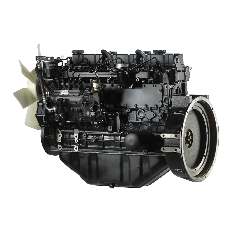
Page 7: Outline
GENERAL Outline 1.1 External View Oil level gauge Fuel injection pump Fuel injection nozzle Fuel filter Inlet manifold Water pump Water drain plug Front Rear Fuel feed pump Flywheel Relief valve Oil filter Oil pan Stop solenoid Oil drain plug Left View Exhaust manifold Alternator... -
Page 8: Engine Serial Number Location
GENERAL 1.2 Engine Serial Number Location The engine serial number is located on the side of the crankcase. Engine serial number Engine serial number location... -
Page 9: Specifications
GENERAL Specifications Model designation Type Water-cooled, 4-stroke cycle No. of cylinders – arrangement 6 –in line Combustion chamber type Swirl chamber Valve mechanism Overhead Cylinder bore × stroke 94 × 120 (3.70 × 4.72) mm (in.) Piston displacement liter (cu in.) 4.996 (305) Compression ratio 22 : 1... - Page 10 GENERAL Model designation Refill capacity (engine water jacket) 9.0 (2.4) liter (U.S. gal.) Type Centrifugal Speed ration to crankshaft Water pump Capacity 160 (42.3) at 0.07 MPa (7.5 kgf/cm ) [107 psi] Cooling system liter (U.S gal.)/min/min discharge pressure of pump running at 3600 min Low-edge B type V-belt ×...
-
Page 11: Tips On Disassembly And Reassembly
GENERAL Tips on Disassembly and Reassembly This service manual covers recommended procedures to 3.2 Reassembly be followed when servicing diesel engines. It also (1) Wash all engine parts, except oil seals, O-rings, contains information on special tools required and basic rubber seals, etc. -
Page 12: Maintenance Standards
MAINTENANCE STANDARDS 1. Maintenance Standards Table ............2 – 1 2. Tightening Torques ................2 – 6 2.1 Important Bolts and Nuts ..............2 – 6 2.2 Standard Bolts ................2 – 7 2.3 Standard Studs ................2 – 7 2.4 Standard Plugs ................ -
Page 13: Maintenance Standards Table
MAINTENANCE STANDARDS Maintenance Standards Table Unit: mm (in.) Repair Service Nominal Assembly Standard Inspection Point Limit Limit Remark Value [Standard Clearance] [Clearance] [Clearance] −1 Maximum min , (no-load) According to engine Adjust governor setting. specification −1 Minimum min , (no-load) Compression pressure 3.2 (33) [469] 2.8 (29) - Page 14 MAINTENANCE STANDARDS Unit: mm (in.) Repair Service Nominal Assembly Standard Inspection Point Limit Limit Remark Value [Standard Clearance] [Clearance] [Clearance] Warpage of gasket contact 0.05 (0.0020) 0.20 Regrind if warpage is minor. surface or less (0.0079) Cylinder head Compressed thickness of 1.2 (0.05) ±0.05 (±0.002) gasket...
- Page 15 MAINTENANCE STANDARDS Unit: mm (in.) Repair Service Nominal Assembly Standard Inspection Point Limit Limit Remark Value [Standard Clearance] [Clearance] [Clearance] Fillet radius of journal and 3 (0.12) ±0.2 (±0.008) crankpin If thrust plate clearance exceeds the repair limit, Crankshaft replace thrust plates. [0.100 to 0.264 [0.300 If it is exceeded, use oversize...
- Page 16 MAINTENANCE STANDARDS Unit: mm (in.) Repair Service Nominal Assembly Standard Inspection Point Limit Limit Remark Value [Standard Clearance] [Clearance] [Clearance] 0.02 (0.0008) 0.05 Straighten by cold working Deflection or less (0.0020) or replace. 6.184 + 0.1 Inlet valve 46.916 6.684 (0.2631) −...
- Page 17 MAINTENANCE STANDARDS Unit: mm (in.) Repair Service Nominal Assembly Standard Inspection Point Limit Limit Remark Value [Standard Clearance] [Clearance] [Clearance] Make shim adjustment. 11.77 11.77 to 12.75 Valve opening pressure Pressure varies by 1 (10) (120) (120 to 130) MPa (kgf/cm ) [psi] [142] per 0.1 mm (0.004 in.) [1707]...
-
Page 18: Tightening Torques
MAINTENANCE STANDARDS Tightening Torques 2.1 Important Bolts and Nuts Thread Width Tightening Torque Dia. × Pitch Description across flats, Remark N·m kgf·m lbf·ft (M-thread) M12 × 1.75 Cylinder head 113 to 123 11.5 to 12.5 83 to 90 M8 × 1.25 Rocker cover 10.0 to 13.0 1.0 to 1.3... -
Page 19: Standard Bolts
MAINTENANCE STANDARDS 2.2 Standard Bolts Torque Thread Diameter (mm) N·m kgf·m lbf·ft N·m kgf·m lbf·ft 2.94 to 4.90 0.3 to 0.5 2.17 to 3.62 7.89 to 9.80 0.8 to 1.0 5.79 to 7.23 9.80 to 12.7 1.0 to 1.3 7.23 to 9.40 14.7 to 21.6 1.5 to 2.2 10.8 to 15.9... -
Page 20: Sealants And Lubricants Table
New parts may be updated due to improvement. Fuel and Exhaust system repairs should only be conducted by an authorized Mitsubishi forklift dealer. Tampering or adjusting the fuel system components will void the warranty and could be in... -
Page 21: Special Tools
SPECIAL TOOLS Special Tool List ..................3 – 1... -
Page 22: Special Tool List
SPECIAL TOOLS Special Tool List Tool name Part No. Shape Valve spring pusher 30691 - 04500 Valve spring removal/ installation Valve guide remove 32A91 - 00300 Valve guide removal Stem seal installer 32A91 - 10200 Valve stem installation Valve seat insert Inlet valve: Valve seat installation caulking tool... - Page 23 SPECIAL TOOLS Tool name Part No. Shape Valve guide installer 32A91 - 00100 Valve guide installation Idler bushing installer 30091 - 07300 Idler gear bushing removal Oil seal sleeve 30691 - 13010 Crankshaft rear oil seal sleeve installer set installation Gauge adapter 30691 - 21100 Compression pressure...
- Page 24 SPECIAL TOOLS Tool name Part No. Shape Connecting rod 32A91 - 00500 Connecting rod bushing bushing puller removal/installation Camshaft bushing 30691 - 00010 Camshaft bushing removal/ installer set installation Oil pump bushing 32A91 - 00400 Oil pump bushing installation installer...
- Page 25 OVERHAUL INSTRUCTIONS 1. Determination of Overhaul Timing ..........4 – 1 2. Testing the Compression Pressure ..........4 – 2...
- Page 26 Fuel and Exhaust system (c) Increased engine oil consumption repairs should only be conducted by an authorized Mitsubishi forklift dealer. (d) Increased blow-by gas volume through the breather Tampering or adjusting the fuel system due to abrasion at the cylinder liner and the piston...
- Page 27 New parts may be updated the compression pressure. due to improvement. Fuel and Exhaust system repairs should only be conducted by an authorized Mitsubishi forklift dealer. Tampering or adjusting the fuel system Unit: MPa (kgf/cm ) [psi]...
- Page 28 ADJUSTMENTS, BENCH TEST, PERFORMANCE TESTS 1. Adjustments ..................5 – 1 1.1 Valve Clearance ................5 – 1 1.2 Fuel System Bleeding ..............5 – 2 1.3 Fuel Injection Timing ..............5 – 3 1.4 No-load Minimum (Idle) Speed and Maximum Speed Setting..5 – 4 1.5 V-belt Inspection and Adjustment ............
-
Page 29: Adjustments, Bench Test, Performance Tests
ADJUSTMENTS, BENCH TEST, PERFORMANCE TESTS Adjustments 1.1 Valve Clearance Valve clearance should be inspected and adjusted when the engine is cold. Item Assembly Standard Inlet Valve clearance 0.25 mm (0.0098 in.) (cold setting) Exhaust (1) Inspection (a) Inspect the valve clearance in the injection sequence. -
Page 30: Fuel System Bleeding
ADJUSTMENTS, BENCH TEST, PERFORMANCE TESTS 1.2 Fuel System Bleeding (1) Fuel filter Air vent plug (a) Loosen the air vent plug of the fuel filter by 1.5 full turns. Air vent plug NOTE Cover the plug with a cloth to prevent fuel from splashing. -
Page 31: Fuel Injection Timing
ADJUSTMENTS, BENCH TEST, PERFORMANCE TESTS 1.3 Fuel Injection Timing The injection timing varies according to the output, speed and specifications of the engine. Be sure to verify the timing by referring to the specifications. (1) Bringing the No.1 cylinder piston to the top dead center on compression stroke (a) Put socket (58309-73100) on the crankshaft pulley Crankshaft pulley... -
Page 32: No-Load Minimum (Idle) Speed And Maximum Speed Setting
The set bolts are sealed. These settings are to be inspected and adjusted by a Mitsubishi forklift dealer only. (2) After adjusting the governor by breaking the seals, be sure to re-seal all visible stoppers, making them appear as if they were sealed at the factory. - Page 33 BUY NOW Then Instant Download the Complete Manual Thank you very much! ...
Need help?
Do you have a question about the S6S and is the answer not in the manual?
Questions and answers