Table of Contents
Advertisement
HUSSONG MANUFACTURING CO., INC.
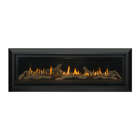
SLAYTON-60
Model #SLA-60
Direct Vent Linear Gas Fireplace
WARNING:
FIRE OR EXPLOSION HAZARD
Failure to follow safety warnings exactly
could result in serious injury, death, or
property damage.
ͷ Do not store or use gasoline or other
flammable vapors and liquids in the
vicinity of this or any other appliance.
ͷ WHAT TO DO IF YOU SMELL GAS
• Do not try to light any appliance.
• Do not touch any electrical switch; do
not use any phone in your building.
• Leave the building immediately.
• Immediately call your gas supplier from
a neighbor's phone. Follow the gas
supplier's instructions.
• If you cannot reach your gas supplier,
call the fire department.
ͷ Installation and service must be performed
by a qualified installer, service agency or
the gas supplier.
This
appliance
an
aftermarket,
manufactured home (USA only) or mobile
home, where not prohibited by local codes.
This appliance is only for use with the type
of gas indicated on the rating plate. This
appliance is not convertible for use with
other gases, unless a certified kit is used.
Hussong Mfg. Co., Inc. • SLA-60
may
be
installed
permanently
located,
INSTALLER: Leave this manual with the appliance.
CONSUMER: Retain this manual for future reference.
Tested &
Listed By
C
OMNI-Test Laboratories, Inc.
in
English
and
available through your local dealer. Visit our website
www.kozyheat.com or scan the QR code for our mobile app.
Les manuels d'installation en français et en anglais sont
disponibles chez votre détaillant local. Visitez www.kozyheat.
com ou scannez ce code QR pour notre application mobile.
Report No: 0216GF048S • Rev. 1, September 2015
Installation and
Operation Manual
Portland
Oregon USA
US
French
installation
manuals
are
Advertisement
Table of Contents

Subscribe to Our Youtube Channel
Related Manuals for kozy heat SLAYTON-60


Summary of Contents for kozy heat SLAYTON-60
- Page 1 Installation and Operation Manual HUSSONG MANUFACTURING CO., INC. SLAYTON-60 Model #SLA-60 Direct Vent Linear Gas Fireplace WARNING: Tested & Portland FIRE OR EXPLOSION HAZARD Listed By Oregon USA Failure to follow safety warnings exactly OMNI-Test Laboratories, Inc. could result in serious injury, death, or property damage.
- Page 3 CONGRATULATIONS! We welcome you as a new owner of a Kozy Heat gas fireplace. Kozy Heat products are designed with superior components and materials, and assembled by trained craftsmen who take pride in their work. To ensure you receive a quality product, the burner and valve assembly are 100 percent test-fired, and the complete fireplace is thoroughly inspected before packaging.
-
Page 5: Table Of Contents
TABLE OF CONTENTS TABLE OF CONTENTS ..............5 8.0 VENTING .................. 26 8.1 Approved Vent Systems ...............26 1.0 INTRODUCTION ..............7 8.2 Venting Requirements ..............26 1.1 Appliance Certification ..............7 8.3 Elbows ....................26 1.2 Requirements for the Commonwealth of Massachusetts ..7 8.4 Restrictor Plate Assembly and Installation .......26 2.0 SPECIFICATIONS .............. -
Page 7: Introduction
1.0 INTRODUCTION 1.1 Appliance Certification OBSTRUCTIONS”. Laboratory: OMNI-Test Laboratories in Portland, Oregon 1.2.4 Inspection Standards: The state or local gas inspector of the side wall horizontally vented gas fueled equipment shall not approve the installation ANSI Z21.88-2014/CSA 2.33-2014, Vented Gas Fireplace Heaters unless, upon inspection, the inspector observes carbon monoxide CGA 2.17-M91 (R2009), Gas-Fired Appliances for Use at High detectors and signage installed in accordance with the provisions... -
Page 8: Specifications
2.0 SPECIFICATIONS 2.1 Appliance Components Part Number Description SL60-160 Control Board Assembly SL60-135 Burner Assembly SL60-SLK Light Kit 700-203 Manual Gas Shut-off Valve SL60-057T Glass Frame Assembly SL42-028 Fan Kit (2)-75 CFM 700-508 Remote Control SL36-085 5 in (127 mm) Restrictor Plate SL60-HHS Vent Heat Shield Assembly 2.1.1 Additional Components Required... -
Page 9: Appliance Dimensions
2.3 Appliance Dimensions ⁄ ” ⁄ 19” ” (252mm) (483mm) (252mm) ⁄ ⁄ ” ” (306mm) (402mm) ⁄ ” ⁄ ” (10mm) (1805mm) LEFT SIDE FRONT RIGHT SIDE ¾ ” ⁄ ” (147mm) (272mm) ⁄ ” ⁄ ⁄ ” ” (1560mm) GAS LINE GAS LINE... -
Page 10: Safety Barrier Dimensions
2.4 Safety Barrier Dimensions 2.4.1 Safety Barrier Installation Center the screen front over the glass frame assembly, WARNING: A barrier designed to reduce the risk of burns from allowing the screen front’s mounting brackets to fit inside the the hot viewing glass is provided with this appliance and shall air openings. -
Page 11: Framing
3.0 FRAMING 3.1 Appliance Placement Top stand-off brackets must be formed and attached prior to positioning fireplace into framed opening. Considerations Remove and save (4) screws securing stand-off heat shields WARNING: Due to high temperatures, the appliance should be and stand-off brackets on top of the fireplace. located out of traffic and away from furniture and draperies. -
Page 12: Clearances To Combustibles
3.3 Clearances to Combustibles Table 3.1, Minimum Appliance Clearances to Combustible Material From appliance top stand-offs 0 in 0 mm From appliance left and right side stand-offs 0 in 0 mm From appliance back stand-offs 0 in 0 mm From appliance bottom stand-offs 0 in 0 mm From appliance corners... -
Page 13: Wall Enclosure Rough Opening
3.4 Wall Enclosure Rough Opening • This fireplace may be elevated off the floor as shown below, provided it is properly supported by framing materials and WARNING: Provide adequate clearances around air openings maintains ceiling clearances. into the combustion chamber. Provide adequate clearance in •... -
Page 14: Floor Support And Protection
3.5 Floor Support and Protection • The fireplace must be placed directly on a wood or non- combustible surface (not linoleum or carpet) extending the entire depth and width of the fireplace. ¼ ” • If this appliance is to be installed directly on carpeting, tile, (1581mm) or other combustible material other than wood flooring, this appliance shall be installed on a metal or wood panel... -
Page 15: Vent Termination Framing
3.7 Vent Termination Framing 3.7.2 Horizontal Terminations IMPORTANT: Horizontal vent sections require 1/4 in (6 mm) rise IMPORTANT: Vent cap location must be in compliance with for every 12 in (305 mm) of travel. Section 7.2 Minimum Termination Clearances on page 25. NOTE: Wall thimble products that comply with the required 1 WARNING: DO NOT RECESS THE VENT CAP INTO WALL OR in (25 mm) clearance to combustibles must be installed for all... -
Page 16: 970 Heat Duct Kit
4.0 #970 HEAT DUCT KIT 4.2 Specifications CAUTION : Read and follow instructions carefully prior to and during the installation of the optional heat duct kit. • The appliance is manufactured with (2) heat duct knock-outs. WARNING: Installation of this heat duct kit and its electrical One, or both, may be utilized. -
Page 17: Attach Heat Duct To Fireplace
4.3 Attach Heat Duct to Fireplace which controls fan speed and operation. Bend the tabs on fireplace top up. With circulation holes facing down, use (3) screws to fasten the tabs to the duct collar. Secure the flexible pipe to the duct collar. Verify screws penetrate both the flexible pipe and the duct collar. -
Page 18: Run And Secure Duct Pipe
4.6 Run and Secure Duct Pipe 4.6.1 Oval Duct Pipe Run the oval and round duct pipe to the register location. Shape the 6 in (152 mm) round duct pipe to fit outside the oval duct pipe. Secure with the screws provided. Slide the oval duct pipe over the oval collar on the register mounting bracket. -
Page 19: Facing And Finishing
5.0 FACING AND FINISHING 5.1 Nailing Flange Assembly Secure the nailing flanges to the fireplace with screws (provided) through the slots in nailing flanges. and Installation Bend perforation on nailing flange until parallel with fireplace NOTE: Depending on facing material, tabs can be adjusted face. -
Page 20: Facing Requirements
5.2 Facing Requirements • Do not secure material to the lower cover panel using screws. This may damage control system components. WARNING: Maintain all minimum clearances to combustibles To secure material in this zone, use a silicone sealant that from the appliance and vent system. has a 300°F (149°C) continuous exposure rating. -
Page 21: Mantel Requirements
5.3 Mantel Requirements EACH SQUARE REPRESENTS 1” (25mm) ¼ OF MANTEL PROJECTION ” (1581mm) 12” (305mm) ⁄ 9” (229mm) ” (792mm) ¼ ¼ ” ” (483mm) (362mm) FINISHING EDGE ¼ ” (1022mm) FIREPLACE ENCLOSURE FLOOR FACING AND FINISHING 21... -
Page 22: Optional Trim Kit Assembly #Sl60-Ftk
5.4 Optional Trim Kit Align the top and bottom trim panels with the pre-drilled holes on the fireplace face. Position the flange on the trim Assembly #SL60-FTK panel as pictured below. Secure with screws included in components packet. For use ONLY with safety barrier #SL60-RSF. IMPORTANT: This trim kit assembly must be attached before Align the left and right trim panels with the pre-drilled holes on the fireplace face. -
Page 23: Gas Line Connection
6.0 GAS LINE CONNECTION 6.1 Gas Conversion (sold separately) ATTENTION: The conversion shall be carried out in accordance with the requirements of the provincial authorities having jurisdiction and in accordance with the requirements of the ANSI Z223.1 installation code. This fireplace is manufactured for use with natural gas. Follow the instructions included with the conversion kit if converting to LP gas. -
Page 24: Termination Locations
7.0 TERMINATION LOCATIONS 7.1 Vertical Vent Cap Termination WARNING: This gas appliance must not be connected to a chimney serving any other appliance. LOWEST DISCHARGE OPENING APPROVED CAP MINIMUM *12” (.30 m) APPROVED VENT PIPE ROOF PITCH = x/12 H - MINIMUM HEIGHT FROM ROOF TO LOWEST DISCHARGE OPENING *If vent is closer than 12 in (.30 m), it must terminate at least 2 ft (.61 m) higher than any portion of a building within 10 ft (3.05... -
Page 25: Minimum Termination Clearances
7.2 Minimum Termination Clearances AREA WHERE TERMINAL IS NOT PERMITTED Figure 7.2, Vent Cap Locations Canadian installations US installations Clearance above grade, veranda, porch, deck, or balcony 12 in (30 cm) 12 in (30 cm) Clearance to window or door that may be opened 12 in (30 cm) 9 in (23 cm) Clearance to permanently closed window (recommended to prevent condensation... -
Page 26: Venting
12.2.2 Vent Restriction on page 44 outlines restrictor plate recommendations depending on burner flame appearance, and EXCELDirect 5” x 8” Horizontal & Vertical instructions on installation after venting is completed. Kozy Heat 800 Series Flexible Horizontal Only Vent Kit RESTRICTOR PLATE... -
Page 27: Vertical Terminations
8.5 Vertical Terminations NATURAL GAS AND LP GAS VERTICAL VENT DIAGRAM (A) Stand-off Brackets (E) Horizontal Vent Heat IMPORTANT: The vertical vent heat shield must be installed for Shield (not applicable) (B) Stand-off Heat Shields every type of venting application. Refer to Section 8.8 on page (F) Termination Cap (C) 90°... -
Page 28: Combination Venting
8.6 Combination Venting NATURAL GAS MINIMUM HORIZONTAL VENTING DIAGRAM (A) Stand-off Brackets (D) Vertical Vent Heat Shield 8.6.1 Natural Gas Installations (B) Stand-off Heat Shields (E) Horizontal Vent Heat Shield IMPORTANT: The vertical vent heat shield included with this (C) 90° Elbow (F) Termination Cap fireplace must be installed for all venting configurations. - Page 29 8.6.2 LP Gas Installations LP GAS MINIMUM HORIZONTAL VENTING DIAGRAM (A) Stand-off Brackets (D) Vertical Vent Heat Shield IMPORTANT: The vertical vent heat shield included with this (B) Stand-off Heat Shields (E) Horizontal Vent Heat Shield fireplace must be installed for all venting configurations. The (C) 90°...
-
Page 30: 800-1 Series Direct Vent Termination Kit(S)
8.7 #800-1 Series Direct Vent exterior wall, and seal. Termination Kit(s) (OPTIONAL) insulate the wall-pass through with any unfaced insulation products listed as non-combustible per ASTM E IMPORTANT: The vertical vent heat shield included with this 136. fireplace must be installed for all venting configurations. The Apply a liberal bead of exterior sealant around outer edge of horizontal vent heat shield must be installed when incorporating termination box (A), placing assembly through the wall-pass... -
Page 31: Vent Heat Shield Assembly Installation
8.8 Vent Heat Shield Assembly Installation IMPORTANT: The vertical vent heat shield MUST be installed for every type of venting application. The horizontal vent heat shield must be installed when incorporating minimum horizontal VENT STAND-OFF TAB venting. NOTE: There are (6) screw holes located in front of the flue outlet to offset the vent heat shield assembly in front of the vent pipe. -
Page 32: Fireplace Set Up
9.0 FIREPLACE SET UP 9.1 Glass Frame Assembly 9.3 Glass Media Installation WARNING: Do not operate this fireplace with the glass removed, WARNING: DO NOT BLOCK PILOT WITH GLASS MEDIA. A cracked, or broken. Replacement of the glass assembly should BLOCKED PILOT MAY CAUSE DELAYED IGNITION. -
Page 33: Control Board Removal And Installation
9.4 Control Board Removal and Installation WARNING: If burner and/or pilot have been burning, use appropriate protection to avoid burns or damage to personal property before removing any components. DO NOT OPERATE THIS APPLIANCE WITHOUT THE SEALING GASKET (LOCATED UNDER THE CONTROL BOARD) IN PLACE. IF GASKETING IS DAMAGED, IT MUST BE REPLACED. -
Page 34: Electrical Information
10.0 ELECTRICAL INFORMATION WARNING: Do not use this fireplace if any part has been under with the National Electrical Code, ANSI/NFPA 70, or the Canadian water. Immediately call a qualified service technician to inspect Electrical Code, CSA C22.1. this appliance and to replace any part of the control system and 10.2 Wiring Requirements any gas control which has been under water. -
Page 35: Operating Instructions
11.0 OPERATING INSTRUCTIONS FOR YOUR SAFETY READ BEFORE OPERATING WARNING: If you do not follow these instructions exactly, a fire or explosion may result causing property damage, personal injury, or loss of life. This appliance is equipped with an ignition device which phone. -
Page 36: Setup Proflame
11.1 Setup Proflame 2 IFC Module • Turn the main burner OFF by setting the ON/OFF switch in the OFF position. The pilot will remain lit even if burner is turned Set the main ON/OFF rocker switch in the OFF position. off, provided CPI mode is turned on. -
Page 37: Ifc Module Ignition Sequence
11.6 IFC Module Ignition Sequence The IFC module will try (2) times for ignition, each lasting approximately (60) seconds, with approximately (35) seconds between each attempt. With the system in OFF position, press the remote control ON/OFF key. Approximately (4) seconds after this key is depressed, the IFC module will generate sparks to the pilot hood. -
Page 38: Remote Control Operation
PROFLAME 2 TRANSMITTER LCD DISPLAY KEY LOCK TRANSMISSION LOW BATTERY ALARM THERMOSTAT OFF/ON/SMART ROOM BLUE BACK TEMPERATURE LCD DISPLAY CPI MODE SET POINT TEMPERATURE/LEVEL/STATE FLAME ON SPLIT FLOW ON/OFF KEY THERMOSTAT KEY LIGHT ON UP/DOWN ARROWS MODE KEY 11.8 Remote Control Operation 11.8.3 Pilot Ignition Selection (IPI/CPI) This system has the option of a continuous (standing) pilot. -
Page 39: Smart Thermostat
11.8.4 Turn ON the Appliance ROOM TEMPERATURE With the system in the OFF position, press the remote control ON/OFF key to turn ON the appliance. A single ‘beep’ will emit from the IFC module to confirm reception of the command. The LCD screen will display all active icons, and the IFC module will start the ignition sequence. -
Page 40: Fan Speed Control
11.8.8 Split Flow Control 11.8.11 Remote Control Low Battery Detection The secondary burner is controlled by the split flow. To activate Remote control battery lifespan depends on various factors this function, including battery quality, number of ignitions, changes to room thermostat set point, etcetera. -
Page 41: Adjustment
12.0 ADJUSTMENT 12.1 Pressure Testing 12.1.2 Manifold Pressure Test Light pilot. NOTE: The appliance and its appliance main gas valve must be disconnected from the gas supply piping system during any Loosen manifold (OUT) pressure tap by turning screw pressure testing of the system at test pressures in excess of ½ counter-clockwise. -
Page 42: Flame Appearance Adjustment
12.2 Flame Appearance Adjustment Table 12.4, Flame Appearance Venturi Adjustment WARNING: To avoid property damage or personal injury, allow Flame Characteristic Cause Solution the fireplace ample time to cool before making any adjustments. Dark, orange flame Venturi closed too far Open venturi slightly with black tips Burner flame appearance and characteristics are affected by... -
Page 43: Restrictor Plate Installation
12.2.2 Vent Restriction Reinstall termination access panel by inserting tabs in panel into slots in baffle. Secure with (2) screws previously WARNING: To avoid property damage or personal injury, allow removed. the fireplace ample time to cool before making any adjustments. Reinstall all components previously removed. -
Page 44: Troubleshooting
13.0 TROUBLESHOOTING ATTENTION: Troubleshooting must be performed by a qualified • Verify all connections between the wire harnesses and the technician. system components are proper and positive. Before proceeding with the steps in the following troubleshooting • Verify the communication link is established between the guide, remote control and the IFC module. - Page 45 Issue Cause Solution Pilot and burner No LP (propane) gas in tank Check LP (propane) tank. Refill if necessary. extinguish while in Incorrect glass assembly Refer to Section 9.1 Glass Frame Assembly on page 32. operation installation Incorrect vent cap installation Adjust if necessary.
-
Page 46: Maintenance
14.0 MAINTENANCE 14.2 Fan(s) ATTENTION: Installation and repair should only done by a qualified service person. The appliance should be inspected CAUTION: Label all wires prior to disconnection when servicing before use and at least annually by a professional service controls. -
Page 47: Replacement Parts List
15.0 REPLACEMENT PARTS LIST Replacement parts are available through your local dealer. Contact your local dealer for availability and pricing. CONTROL BOARD AND PARTS Control Board - NG SL60-160 Valve Step Motor - LPG 700-504-1 Control Board - LPG SL60-161 18 in. Flexible Gas Line - Black 700-213B S.I.T. -
Page 49: Limited Warranty
Hussong Manufacturing Co., Inc. warranties to the original all times, according to the operating instructions furnished. purchaser of this Kozy Heat Fireplace, that it is free of defects in This warranty is limited to defects in material and workmanship. It materials and workmanship at the time of manufacture. -
Page 51: Lifetime Warranty
Kozy Heat Fireplace will not be defective in than those incurred by Hussong Manufacturing Co., Inc. to repair material or workmanship under normal use and service for as long or replace the defective component.
Need help?
Do you have a question about the SLAYTON-60 and is the answer not in the manual?
Questions and answers