Table of Contents
Advertisement
Quick Links
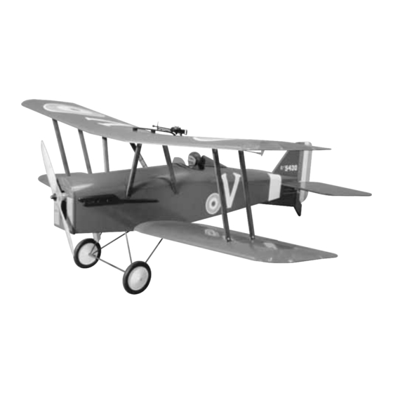
• QUICK BUILDING – IDEAL FOR FUN-SCALE COMPETITION
• SMOOTH-FLYING BIPE – CAPABLE OF SCALE AEROBATICS
READ THROUGH THIS MANUAL BEFORE STARTING CONSTRUCTION. IT
CONTAINS IMPORTANT INSTRUCTIONS AND WARNINGS CONCERNING THE
ASSEMBLY AND USE OF THIS MODEL.
Wingspan: 64 in [1625mm]
Wing Area: 1440 sq in [93dm
Weight: 12.0 - 13.5 lb [5440 - 6120g]
Wing Loading: 19.2 - 21.3 oz/sq ft [59 - 65g/dm
Fuselage Length: 53 in [1345mm]
Engine: .61 - 1.20 cu in [10.0 - 19.5cc] two-stroke, .91 - 1.20 cu in
[15.0 - 19.5cc] four-stroke
Radio: 4-channel, 7 or 8 servos (single or dual elevator servos)
Dynaflite
™
guarantees this kit to be free from defects in both material and workmanship at the
date of purchase. This warranty does not cover any component parts damaged by use or
modification. In no case shall Dynaflite's liability exceed the original cost of the
purchased kit. Further, Dynaflite reserves the right to change or modify this warranty without
notice. In that Dynaflite has no control over the final assembly or material used for final
assembly, no liability shall be assumed nor accepted for any damage resulting from the use by
the user of the final user-assembled product. By the act of using the user-assembled product,
the user accepts all resulting liability. If the buyer is not prepared to accept the liability
associated with the use of this product, the buyer is advised to return this kit
immediately in new and unused condition to the place of purchase.
SE5AP03 for DYFA3045 Printed in USA V1.1
™
• 64" WINGSPAN (IMAA Legal)
2
]
2
]
WARRANTY
Instruction Manual
Entire Contents © Copyright 2007
Advertisement
Table of Contents

Related Manuals for Hobbico Dynaflite S.E.5a


Summary of Contents for Hobbico Dynaflite S.E.5a
- Page 1 ™ • QUICK BUILDING – IDEAL FOR FUN-SCALE COMPETITION • 64" WINGSPAN (IMAA Legal) • SMOOTH-FLYING BIPE – CAPABLE OF SCALE AEROBATICS READ THROUGH THIS MANUAL BEFORE STARTING CONSTRUCTION. IT CONTAINS IMPORTANT INSTRUCTIONS AND WARNINGS CONCERNING THE ASSEMBLY AND USE OF THIS MODEL. Wingspan: 64 in [1625mm] Wing Area: 1440 sq in [93dm Weight: 12.0 - 13.5 lb [5440 - 6120g]...
-
Page 2: Table Of Contents
FINAL ASSEMBLY ........46 corrections to this model visit the web site Glue in the Stab & Fin ..........46 listed below and select the Dynaflite S.E.5a. If Hinge the Control Surfaces ........48 there is new technical information or changes to Finish the Wing Struts ..........48 Finish the Radio Installation ........51... -
Page 3: Imaa
PROTECT YOUR MODEL, YOURSELF & OTHERS... SCALE COMPETITION FOLLOW THESE IMPORTANT Though the Dynaflite S.E.5a may not have the SAFETY PRECAUTIONS same level of detail as an “all-out” scratch-built competition model, it is a scale model nonetheless and is therefore eligible to 1. -
Page 4: Decisions You Must Make
(217) 398-8970, or e-mail The Dynaflite S.E.5a may be operated with us at productsupport@greatplanes.com. If either seven or eight servos. The elevators are... -
Page 5: Engine Recommendations
(3) Y-harnesses for ailerons (HCAM2751 for flown today. The Dynaflite S.E.5a flies most Futaba) scale-like with engines nearer the bottom of the R/C foam rubber (1/4" [6mm] - HCAQ1000, recommended size range. -
Page 6: Adhesives & Building Supplies
William’s Brothers #13300 5" [127mm] X-Acto ® #240 razor saw (XACR1440) Vintage Wheels (WBRQ1133) Sanding tools and sandpaper assortment 1/2" [13mm] double-sided foam mounting (see “Easy-Touch ™ Bar Sander” section) tape (GPMQ4440) Velcro hook and loop material (for COVERING TOOLS mounting battery pack, GPMQ4480) Great Planes long-handle 3/32"... -
Page 7: Important Building Notes
Here’s the complete list of Easy-Touch Bar D.G. Products Perma-Grit tungsten Sanders and Adhesive Backed Sandpaper: carbide flat sanding bar Heat shrink tubing (for securing servo wire 5-1/2" [140mm] Bar Sander (GPMR6169) connections inside wings, GPMM1058) 11" [280mm] Bar Sander (GPMR6170) K &... -
Page 8: Metric Conversions
Machine screws are designated by a number, use only 30-minute (or 45-minute) epoxy, threads per inch, and a length. because you will need the working time and/or the additional strength. • Photos and sketches are placed before the step they refer to. Frequently you can study photos in following steps to get another view of For example 4-40 x 3/4"... -
Page 9: Die Drawings
Die Drawing... -
Page 10: Die Drawings
Die Drawing... -
Page 11: Label The Parts
and one 1/4" x 3/8" x 18" [6.4 x 9.5 x 460mm] balsa stick. Use T-pins to hold the sticks down as LABEL THE PARTS you proceed. Note the angles on the ends of some of the sticks (indicated by the arrows in Use the die drawings on pages 9 and 10 to the photo) are not cut until the next step. - Page 12 6. Reposition the plan so the stab is over the building board. Don’t forget to cover it with Plan Protector or wax paper. Use the sticks left 9. Use a Great Planes Slot Machine to cut the over from the fin and rudder plus four more 3/8" hinge slots on the centerlines in the stab and x 1/2"...
-
Page 13: Build The Wing
With the control surfaces temporarily joined, How to cut hinge slots with a hobby knife sand the outer edges of all the parts round (except for where they are hinged). When using a hobby knife to cut hinge slots, one of the most common mistakes made by 11. - Page 14 Use the “crossed-pin” technique to pin the pieces. Glue them into the notches in the top of spars to the plan over the location for the the ribs for the forward and aft top spars. The forward and aft bottom spars. same as when gluing the ribs to the bottom spars, use a small builder’s triangle to hold the ribs–especially the outer ribs–vertical as you glue.
- Page 15 “CTE”) as a pattern, make an additional center panel trailing edge from a 3/32" x 3" x 24" [2.4 x 76 x 610mm] balsa sheet. Save the remainder of the sheet for the top center panel. 13. Cut out the bottom sheeting to accommodate the grooved 1/2"...
-
Page 16: Build The Top Center Panel
and sheeting even with the ends. Sand the front the wing plan) and cover it with Plan Protector of the sheeting even with the sub leading edge. or wax paper. 2. The same as was done for the ribs on the ends of the bottom center panel, cut partway through opposite sides of both die-cut 3/32"... -
Page 17: Build The Outer Panels
edge using the 3/32" x 3" [2.4 x 75mm] balsa cut 1/8" [3.2mm] plywood rib R4A, the die-cut sheet left over from making the first center 1/16" plywood rib R4B and the die-cut 3/32" panel trailing edge for the bottom center panel. [2.4mm] balsa rib R4. - Page 18 Refer to this photo for the following 8. Cut the bottom aileron spar from two steps. a 1/8" x 1/4" x 24" [3.2 x 6.4 x 610mm] basswood stick as shown on the plan, then pin it over its location. Save the remainder of the stick for the top.
- Page 19 Refer to this photo for the following Refer to this photo for the following three steps. four steps. 19. Cut the top leading edge sheet from a 3/32" x 3" x 24" [2.4 x 76 x 610mm] balsa 15. Cut the top aileron spar from the sheet.
-
Page 20: Mount The Aileron Servos
24. Repeat the same steps to build the 2. Place a die-cut 1/8" [3.2mm] plywood left top panel, then switch to the other plan servo hatch (HC) over the rails as shown on and build both right panels. Be certain to the plan. -
Page 21: Build The Wing Tips
30" [2.4 x 4.8 x 760mm] balsa stick. Glue the cap 8. While the epoxy is hardening and strips to the rails next to the hatch. the hatch is out of the wing panel, add a few drops of thin CA to the screw holes in the hatch rails. 5. - Page 22 and aft parts of the tip between the aileron spars and the aft spars. 2. Place the wing tip over the plan and mark the location of the tip ribs. Glue one of the die-cut 3/32" [2.4mm] balsa tip ribs (TR) to the wing tip.
- Page 23 11. The same as was done on the tail 8. Use a razor saw to cut the aileron surfaces, mark a centerline on the outer trailing from the outer panel. edge. On the model shown, a ballpoint pen supported by a piece of 1/4" [6.4mm] balsa was used to mark the lines (the lines don’t have to be exactly on center–it’s more important that the lines accurately align with each other).
-
Page 24: Join The Wing Panels
plan. Drill 1/16" [1.6mm] holes for the control matched up correctly (bottom center panel to horn screws. Run the #2 x 3/8" [9.5mm] screws bottom outer panels)! in and out of the control horn mount, remove the screws, then add a few drops of thin CA to the holes and allow to fully harden. -
Page 25: Build The Fuselage
cup. Use an epoxy brush to apply a film of squares dampened with alcohol to wipe away epoxy to the joining ribs on the end of the any more epoxy that squeezes out of the joint. bottom left panel and the bottom center Make certain the leading and trailing edges of panel. - Page 26 4. Switching to the fuselage bottom view, build the fuselage top over the plan from the die-cut 1/8" [3.2mm] plywood forward and aft fuselage tops (FFT, AFT) and two 1/8" x 1/2" x 24" [3.2 x 12.7 x 610mm] balsa sticks. Remove the fuselage top from the plan, then sand flat and even.
- Page 27 Refer to these photos for the following 10. Making certain all the parts fit correctly four steps. and that the fuse top is fully contacting the plan, use medium CA to carefully glue all the formers to the fuse sides and fuse top. Glue the fuselage sides to the fuse top from F3 aft.
- Page 28 of the bottom wing panel on the leading edge and the center of the fuselage at former F3. Center the wing in the fuselage, aligning the marks. 19. Drill 13/64" [5.2mm] holes through the four punchmarks in the front of the firewall. Insert four 8-32 blind nuts into the holes in the back of the firewall and lightly tap them in with 15.
-
Page 29: Mount The Fuel Tank
2. Glue together two pieces of leftover 1/8" x 1/4" [3.2 x 6.4mm] basswood from the wing spars to make a 1/4" x 1/4" [6.4 x 6.4mm] mounting rail for the tank tray. Cut the rail to a length of 3" [75mm]. Glue the rail to the back of former 3 as shown on the plan. - Page 30 2. Using the 18" [460mm] basswood wing struts to set the correct spacing, carefully glue the die-cut 1/8" [3.2mm] balsa spacers (SM) into all four strut mounts without inadvertently gluing in the wing struts (two of the strut mounts are shown in the photo). 4.
-
Page 31: Mount The Engine
Now that the engine is mounted, go ahead and MOUNT THE ENGINE hook up the throttle and do the rest of the hookups while the engine compartment is open and easily accessible. 4. Refer to the side view of the fuselage plan and glue pieces of 1/8"... - Page 32 18" [460mm] pushrod connected to the throttle servo with a nylon clevis and connected to the carburetor with a screw-lock pushrod connector. 7. Make a brace for the aft end of the throttle tube by drilling a 3/16" [4.8mm] hole through a piece of leftover plywood and gluing it to F3 as shown.
-
Page 33: Build The Top Of The Fuselage
BUILD THE TOP OF THE FUSELAGE 3. Cut 4-1/2" [115mm] from each of four more 1/8" x 1/4" x 24" [3.2 x 6.4 x 610mm] balsa sticks and 4-1/2" [115mm] from one 1/4" x 1/4" x 24" [6.4 x 6.4 x 610mm] balsa stick. Save the longer sticks for the aft end of the fuselage. - Page 34 [3.2mm] balsa to the fuse top 3/32" [2.4mm] 9. Before doing any sanding, use balsa filler from the edge between formers F1 and the where required to fill any gaps in the sheeting. firewall and between the firewall and the front Allow the filler to dry, then sand the sheeting strut mounts.
-
Page 35: Final Construction
adjust the position of F7B until the stringer is straight. Glue F7B into that position. Glue the stringer into the notches of the formers. 13. Use the four remaining 1/8" x 1/4" [3.2 x 6.4mm] balsa sticks left over from step 3 and four more 1/8"... - Page 36 wing bolts are to be drilled (the holes are 4" Swing the string over to the same position on [100mm] apart–2" [50mm] both sides of center). the other end of the wing. Adjust the wing and slide the tape along the string until the wing is centered (as shown in A = A in the sketch) and the arrow aligns with both sides of the wing.
-
Page 37: Fit The Stab & Fin
FIT THE STAB & FIN Note: These instructions show how to temporarily fit the stab and fin to the fuselage. After final sanding, the stab, fin and fuselage will be covered. Then, the stab and fin will be permanently glued in. Modelers who prefer to glue the stab and fin to the fuselage before covering may do so after final sanding. - Page 38 making sure B=B as shown in the sketch. The same way you aligned the bottom wing, use the “pin and string” technique to align the stab (insert the pin into the top stringer in the front of the fuselage). Use a ballpoint pen to lightly mark the top and bottom of the fuselage sides onto the stab.
-
Page 39: Make The Tail Gear Mount
plywood tail gear mounts (TGM). Fit a 4-40 blind nut in the inside of both mounts, then use a hammer to securely tap the blind nuts all the way into the wood (do this over a piece of wood so the blind nut can go all the way through). Use a few drops of thin CA to secure the blind nuts. -
Page 40: Mount The Main Landing Gear
wires on the model. With the forward landing MOUNT THE MAIN gear wire in the groove, mount the landing gear straps to the forward landing gear block with LANDING GEAR four #2 x 1/2" [12.7mm] screws. 1. Prepare the prebent 3/16" [4.8mm] forward 4. -
Page 41: Prepare The Wing Struts
still hot, carefully use a paper towel or a cloth to approximately 1/8" [3mm] longer than the wipe away as much of the residual “caramelized” required finished length, so there is no need to soldering flux as possible. cut them longer than the pattern. Note: The procedure of cutting the slots in the ends of the struts for the aluminum strut retainers may appear to be laborious, but if... -
Page 42: Mount The Engine Cowls
MOUNT THE ENGINE COWLS Refer to the following two photos while fitting the bottom engine cowl. 3. Widen the slot with a piece of medium-grit sandpaper folded in half. 4. Finish widening the slot to the correct thickness with a piece of coarse-grit sandpaper folded in half. -
Page 43: Cover The Model
2. Glue tapered strips of leftover 1/16" [1.6mm] balsa to the bottom of the fuselage sides so that when in position, the aft edge of the bottom cowl will be even with the bottom fuselage sheeting. 6. Cut out and test fit the molded plastic front engine cowl to the fuselage. - Page 44 follow these instructions exactly, or simply use tight around the tips. After the covering has them as a guideline while applying your own been ironed around the tips, trim off the excess covering techniques. However you decide to “handle. ” finish your S.E.5a, do not forget to install the “Y”...
-
Page 45: Painting
1/2" [15mm] overlap is suggested. Lastly, the red, white and blue were applied to the rudder as though it were one piece of covering. Use care not to heat the overlapping seams while heating the rest of the covering. Otherwise, the adhesive on the covering will soften, and the seam may pull apart as the covering tightens. -
Page 46: Final Assembly
3. Glue strips of leftover balsa inside the 6. Glue the exhaust pipes into position. The exhaust pipes as shown. Sand the balsa strips head rest will be glued on after finishing the even with the bottom edges of the exhaust cockpit later. - Page 47 5. Test fit the fin into the fuselage. Use a Hobbico Builder’s Triangle or another triangle to be certain the fin is perpendicular to the stab. If necessary, when gluing the fin into position in the next step, use masking tape to pull the stab to one side or the other to get it vertical.
-
Page 48: Hinge The Control Surfaces
4. Add six drops of thin CA to both sides of HINGE THE CONTROL the hinges. Keep a tissue nearby to absorb SURFACES excess CA in case any seeps into the hinge gap or onto the wing. 5. Join the rest of the control surfaces the same way. - Page 49 ❏ 7. Raise or lower the struts as necessary until they are contacting the bottom of the top wing and the leading and trailing edges of the wing are centered in the jigs. As the struts were cut slightly longer than required to allow for adjustment, it may be necessary to remove some or all of the struts and trim them to achieve the adjustment required.
- Page 50 strut retainer. Temporarily install a 4-40 x 1/2" struts (i.e. RF , RR, LF , LR). Remove the top wing [13mm] screw into the strut and strut retainer. and take all the struts off. Hint: When threading in the 4-40 x 1/2" screws, 15.
-
Page 51: Finish The Radio Installation
22. Drill 1/8" [3.2mm] holes through the bottom strut retainers at the marks you made. Fill the strut retainer slots in the bottom wing with 30-minute epoxy, then working quickly, insert the strut retainers, wipe away excess epoxy and mount the struts to the top and bottom strut retainers with the screws. - Page 52 pushrod so the elevator is centered when the servo arm is centered. Refer to this photo for the following three steps. 9. Cut a small hole in the bottom of the top wing near one of the aft strut retainers. Use a small piece of wire with a hook bent on the end to “fish out”...
-
Page 53: Finish The Cockpit
receiver was mounted to the plywood plate (with R/C foam in between) with rubber bands. 13. Connect the servo wires and on/off switch to the receiver and connect the battery to the on/off switch. Connect the end of the “Y” connector for the ailerons to the aileron plug in the receiver (the remaining end of the “Y”... -
Page 54: Machine Gun
similar to the way the exhaust pipes were glued Refer to this photo while making the into position with balsa sticks. machine gun and mount. 5. Cut out the molded clear plastic windscreen. Paint the base black. Position the windscreen on 1. -
Page 55: Apply The Decals
APPLY THE DECALS 1. Use scissors or a sharp hobby knife to cut the decals from the sheet. 2. Be certain the model is clean and free from oily fingerprints and dust. Prepare a dishpan or small bucket with a mixture of liquid dish soap and warm water–about one teaspoon of soap per gallon of water. -
Page 56: Balance The Model (C.g.)
These are the recommended control surface throws: High Rate Low Rate ELEVATOR: 1-1/2" [38mm] up 3/4" [19mm] up 1-1/2" [38mm] down 3/4" [19mm] down RUDDER: 1-1/2" [38mm] right 1" [25mm] right 1-1/2" [38mm] left 1" [25mm] left AILERONS: 1-1/2" [38mm] up 1"... -
Page 57: Balance The Model Laterally
empty fuel tank, have an assistant lift the model to fall off. Use #2 sheet metal screws, RTV at the balance point you marked on the bottom silicone or epoxy to permanently hold the of the top wing. Hint: Instead lifting the model weight in place. -
Page 58: Balance The Propeller
transmitter and receiver batteries the night GROUND CHECK before you go flying, and at other times as recommended by the radio manufacturer. If the engine is new, follow the engine Note Checking the condition of your receiver manufacturer’s instructions to break-in battery pack is highly recommended. -
Page 59: Ama Safety Code (Excerpt)
Keep all engine fuel in a safe place, away from engine an on/off switch should be connected to high heat, sparks or flames, as fuel is very the engine coil. Do not throw anything into the flammable. Do not smoke near the engine or propeller of a running engine. -
Page 60: Imaa Safety Code (Excerpt)
2. I will not fly my model aircraft in the presence Section 3.0: Safety Check of spectators until I become a qualified flier, unless assisted by an experienced helper. 3.4 Flight Testing: All Giant Scale R/C aircraft are to have been flight tested and flight trimmed 3. -
Page 61: Flying
12. Secure connections between servo wires and Y-connectors or servo extensions, The Dynaflite S.E.5a is a great-flying model that and the connection between your battery flies smoothly and predictably. The S.E.5a does pack and the on/off switch with vinyl... -
Page 62: Field Assembly
CAUTION (THIS APPLIES TO ALL R/C AIRPLANES): If, while flying, you notice an alarming or unusual sound such as a low- The Dynaflite S.E.5a handles well on the pitched “buzz, ” this may indicate control ground–similar to most tail draggers such as a surface flutter . -
Page 63: Landing
Dynaflite S.E.5a is similarly nimble model heading straight down the runway. If the with a good climb rate and the ability to wheels are not going straight when the model perform many classic dog-fighting maneuvers touches down it may ground loop. If you’re not including loops, rolls, spins, stall turns, comfortable doing these “slip”... - Page 64 BUILDING NOTES Kit Purchased Date: _______________________ Date Construction Finished:________________ Where Purchased: _________________________ Finished Weight: __________________________ Date Construction Started: _________________ Date of First Flight: ________________________ FLIGHT LOG...
Need help?
Do you have a question about the Dynaflite S.E.5a and is the answer not in the manual?
Questions and answers