
Related Manuals for protech PS3100 Series


Summary of Contents for protech PS3100 Series
- Page 1 USER’S MANUAL PS3100 Series Mini POS Terminal With Intel® Atom® Platform PS3100 Series M1...
- Page 2 Copyright Notice PS3100 Series POS System With LCD / Touchscreen OPERATION MANUAL COPYRIGHT NOTICE This operation manual is meant to assist users in installing and setting up the system. The information contained in this document is subject to change without prior any notice.
- Page 3 Copyright Notice FCC NOTICE This equipment has been tested and found to comply with the limits for a Class A digital device, pursuant to part 15 of the FCC Rules. These limits are designed to provide reasonable protection against harmful interference when the equipment is operated in a commercial environment.
-
Page 4: Table Of Contents
Contents TABLE OF CONTENTS CHAPTER 1 INTRODUCTION About This Manual ............POS Illustration ............. System Specification ............. Safety Precautions ............1-10 CHAPTER 2 SYSTEM CONFIGURATION Jumper & Connector Quick Reference Table ....Component Locations ........... How to Set the Jumpers ..........COM Port Connector …………………………………... - Page 5 Contents LAN Driver Utility ............Sound Driver Utility ............. Intel® Chipset Software Installation Utility ....USB2.0 Software Installation Utility ………………… Touch Screen Driver Utility ………………………….. 3-10 Wireless Driver Utility (Optional) …………………… 3-11 OS Support Table ……………………………………. 3-12 CHAPTER 4 AWARD BIOS SETUP Introduction ..............
- Page 6 Contents APPENDIX B TECHNICAL SUMMARY Block Diagram ................. Interrupt Map ................DMA Channels Map ..............Memory Map ................I/O Map ..................
- Page 7 CHAPTER INTRODUCTION This chapter gives you the information for PS3100 Series. It also outlines the System specifications. Section includes: About This Manual System Specifications Safety precautions Experienced users can skip to chapter 2 on page 2-1 for a Quick Start.
-
Page 8: Appendix B Technical Summary
Chapter 1 Introduction 1-1. ABOUT THIS MANUAL Thank you for purchasing our PS3100 Series System. The PS3100 Series is an updated system designed to be comparable with the highest performance of IBM AT personal computers. The PS3100 Series provides faster processing speed, greater expandability and can handle more tasks than before. - Page 9 Chapter 1 Introduction 1-2. POS SYSTEM ILLUSTRATION PS3100 I-BUTTON TYPE ′ Page: 1-3 PS3100 SERIES USER S MANUAL...
- Page 10 Chapter 1 Introduction PS3100 FINGER PRINTER TYPE ′ Page: 1-4 PS3100 SERIES USER S MANUAL...
- Page 11 Chapter 1 Introduction PS3100 EMPTY TYPE ′ Page: 1-5 PS3100 SERIES USER S MANUAL...
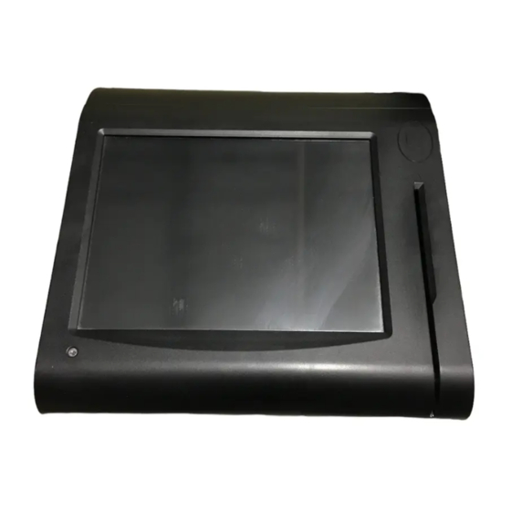
- Page 12 Chapter 1 Introduction PS3100 SIDE VIEW ′ Page: 1-6 PS3100 SERIES USER S MANUAL...
-
Page 13: System Specification
BIOS : PhoenixAward PnP BIOS 4Mbytes with VGA BIOS KEYBOARD CONNECTOR : PS/2 Keyboard, with mini DIN connecter on rear panel MOUSE CONNECTOR : PS/2 Mouse, with mini DIN connecter on rear panel ′ Page: 1-7 PS3100 SERIES USER S MANUAL... - Page 14 0.206(W) x 0.206(H)/ 0.088(W) x 0.264(H) Brightness 300 / 230 cd / m Signal Interface (bit) TTL (18-bit) LCD MTBF 20,000 Back Light MTBF (Hrs) 20,000 TOUCH PANEL : 10.4” 5wire Analog resistive ′ Page: 1-8 PS3100 SERIES USER S MANUAL...
- Page 15 Read only, output through PS/2 KB interface MSR : (OPTIONAL) JIS-I or II, ISO Tracker 1+2+3 (PS/2 KB Interface) Wireless LAN : (OPTIONAL) Mini PCIe Wireless LAN Module (802.11b/g) FINGERPRINT : (OPTIONAL) Embedded Fingerprint module (USB interface) ′ Page: 1-9 PS3100 SERIES USER S MANUAL...
-
Page 16: Safety Precautions
When the outside of the case is stained, remove the stain with neutral washing agent with a dry cloth. b. Never use strong agents such as benzene and thinner to clean the system. ′ Page: 1-10 PS3100 SERIES USER S MANUAL... - Page 17 If dust has been accumulated on the outside, remove it by using a special made vacuum cleaner for computers. e. Please don't contact the surface of capacitive touch before entering your operation system, or capacitive touch may have position problem for electrostatics interference. ′ Page: 1-11 PS3100 SERIES USER S MANUAL...
-
Page 18: Jumper & Connector Quick Reference Table
CHAPTER SYSTEM CONFIGURATION Helpful information that describes the jumper & connector settings, and component locations. Section includes: Jumper & Connector Quick Reference Table Component Locations Configuration and Jumper settings Connector Pin Assignments Page 2-1... - Page 19 JPWR_4P1 2-21 Touch Panel Connector JTP1 2-22 Touch Panel Selection 2-22 Touch Panel Interface Type Selection 2-23 FWH & SPI BIOS Selection 2-24 Clear CMOS Data Selection 2-25 Compact Flash Connector 2-26 Page: 2-2 ’ PS3100 SERIES USER S MANUAL...
-
Page 20: Component Locations
Chapter 2 Hardware Configuration 2-2. COMPONENT LOCATIONS J24VIN1 COM3 PS3100 SERIES Connector, Jumper and Component locations Page: 2-3 ’ PS3100 SERIES USER S MANUAL... -
Page 21: How To Set The Jumpers
PIN1 & PIN2 to create one setting and shorting. You can either connect PIN2 & PIN3 to create another setting. The same jumper diagrams are applied all through this manual. The figure below shows what the manual diagrams look and what they represent. Page: 2-4 ’ PS3100 SERIES USER S MANUAL... - Page 22 Chapter 2 Hardware Configuration JUMPER DIAGRAMS JUMPER SETTINGS Page: 2-5 ’ PS3100 SERIES USER S MANUAL...
-
Page 23: Com Port Connector
RI / +5V / +12V selectable COM1 and COM1_1 can't be used simultaneously. COM3 : COM3 Connector The pin assignments are as follows : ASSIGNMENT DCD3 RXD3 TXD3 DTR3 DSR3 RTS3 CTS3 RI/+5V/+12 selectable Page: 2-6 ’ PS3100 SERIES USER S MANUAL... - Page 24 DTR4 DSR4 RTS4 CTS4 COM1-1 : COM1-1 Connector The pin assignments are as follows : ASSIGNMENT DCD1 RXD1 TXD1 DTR1 DSR1 RTS1 CTS1 RI/+5V/+12 selectable COM1 and COM1_1 can't be used simultaneously. Page: 2-7 ’ PS3100 SERIES USER S MANUAL...
-
Page 25: Com Ri And Voltage Selection
DDCA CLK DCD2 RXD2 TXD2 DTR2 DSR2 RTS2 CTS2 RI/+5V/+12 selectable All COM port is selectable for RI, +5V or +12V. For more information, please refer to our “COM RI and Voltage Selection”. Page: 2-8 ’ PS3100 SERIES USER S MANUAL... - Page 26 2-5. COM PORT RI & VOLTAGE SELECTION JP_COM1 , JP_COM2, JP_COM3: COM Port RI & Voltage Selection The selections are as follows: SELECTION JUMPER JUMPER SETTINGS ILLUSTRATION VCC12 ***Manufacturing Default – RI. Page: 2-9 ’ PS3100 SERIES USER S MANUAL...
-
Page 27: Mini-Dim And Usb Connector
MINI-DIN connector can support keyboard, Y-cable. Please use Y-cable if using PS/2 mouse. The pin assignment is as follows : ASSIGNMENT USB2+ USB2- VCC5 USB3+ USB3- VCC5 KDAT MDAT V5SB KCLK MCLK Page: 2-10 ’ PS3100 SERIES USER S MANUAL... - Page 28 J4 : Internal USB Ports Connector The pin assignment is as follows : ASSIGNMENT USB4- USB4+ VCC5 USB1: Internal USB Ports Connector The pin assignment is as follows : ASSIGNMENT USB7- USB7+ VCC5 Page: 2-11 ’ PS3100 SERIES USER S MANUAL...
-
Page 29: Usb Voltage Selection
V5SB 1-3&2-4 3-5&4-6 *** Manufactory default --- V5SB. JP9, JP10 : USB Voltage Selection The selections are as follows: JUMPER SETTING JUMPER FUNCTION (pin closed) ILLUSTRATION V5SB *** Manufactory default --- V5SB. Page: 2-12 ’ PS3100 SERIES USER S MANUAL... -
Page 30: Lan & Usb Connector
2-8. LAN & USB CONNECTOR JRJ45USB1 : LAN & USB Connector The pin assignments are as follows: ASSIGNMENT LAN1_MDIP0 LAN1_MDIN0 LAN1_MDIP1 LAN1_MDIN1 LAN1_MDIP2 LAN1_MDIN2 LAN1_MDIP3 LAN1_MDIN3 ASSIGNMENT VCC5 USB0- USB0+ VCC5 USB1- USB1+ Page: 2-13 ’ PS3100 SERIES USER S MANUAL... -
Page 31: Cash Drawer Connector
Definition (BIT6) To Open Drawer 2 (GPIO25) Write "48Fh " to I/O Port "20"h To Close Drawer Write "48D " to I/O Port "00"h Detect Drawer2 Status (GPIO15) Read I/O “48D”h Definition (BIT7) Page: 2-14 ’ PS3100 SERIES USER S MANUAL... -
Page 32: Cash Drawer Power Selection
Chapter 2 Hardware Configuration 2-10. CASH DRAWER POWER SELECTION JP2 : Cash Drawer Power Selection The jumper settings are as follows : SELECTION JUMPER SETTINGS JUMPER ILLUSTRATION +12V (default) +24V *** Manufactory default --- +12V. Page: 2-15 ’ PS3100 SERIES USER S MANUAL... - Page 33 Chapter 2 Hardware Configuration JP3 : Cash Drawer Power Selection The jumper settings are as follows : SELECTION JUMPER SETTINGS JUMPER ILLUSTRATION +12V (default) +24V *** Manufactory default --- +12V. Page: 2-16 ’ PS3100 SERIES USER S MANUAL...
-
Page 34: Power Led Connector
SYSFAN1 : Power Switch Connector The pin assignment is as follows : ASSIGNMENT VCC12 2-13. RST SWITCH CONNECTOR JRST1 : Power Switch Connector The pin assignment is as follows : ASSIGNMENT RST_SW Page: 2-17 ’ PS3100 SERIES USER S MANUAL... -
Page 35: Power For Thermal Printer Connector
SPK_OUT1 : External Speaker Connector The pin assignment is as follows : ASSIGNMENT SPK_OUT SPK_GND 2-16. INVERTER CONNECTOR JINV1 : Inverter Connector The pin assignment is as follows : ASSIGNMENT +12V +12V LVDS_BKLTEN BRCTR Page: 2-18 ’ PS3100 SERIES USER S MANUAL... -
Page 36: Msr/ Card Reader Connector
KB_DATA_C (Input) KB_DATA (Output) 2-18. LVDS CONNECTOR LVDS1 : LVDS Connector The pin assignments are as follows : ASSIGNMENT ASSIGNMENT LVDS_VCC LVDS_YAP2 LVDS_VCC LVDS_YAM2 LVDS_YAP1 LVDS_CLKAP LVDS_YAM1 LVDS_CLKAM LVDS_YAP0 LVDS_YAM0 LVDS_VCC LVDS_VCC Page: 2-19 ’ PS3100 SERIES USER S MANUAL... -
Page 37: Sata Connector
2-19. SATA CONNECTOR SATA1 : Serial ATA Connector The pin assignments are as follows: ASSIGNMENT 2-20. SATA POWER CONNECTOR JPWR_4P1 : Serial ATA Connector The pin assignments are as follows: ASSIGNMENT VCC12 Page: 2-20 ’ PS3100 SERIES USER S MANUAL... -
Page 38: Touch Panel Connector
UR (Up Right) UL (Up Left) 2-22. TOUCH PANEL SELECTION JP7 : Touch Panel Selection. The selections are as follows: SELECTION JUMPER JUMPER SETTINGS ILLUSTRATION e-Turbo 1-2&5-6 3-4&7-8 *** Manufactory default --- Elo. Page: 2-21 ’ PS3100 SERIES USER S MANUAL... -
Page 39: Touch Panel Interface Type Selection
Chapter 2 Hardware Configuration 2-23. TOUCH PANEL INTERFACE TYPE SELECTION JP6: Touch Panel Interface Type Selection The selections are as follows: SELECTION JUMPER JUMPER SETTINGS ILLUSTRATION RS-232 Open *** Manufactory default --- USB. Page: 2-22 ’ PS3100 SERIES USER S MANUAL... -
Page 40: Fwh & Spi Bios Selection
Chapter 2 Hardware Configuration 2-24. FWH & SPI BIOS SELECTION JP8 : FWH & SPI SELECTION The selections are as follows : JUMPER SETTING JUMPER (pin closed) ILLUSTRATION FUNCTION Open *** Manufactory default --- SPI. Page: 2-23 ’ PS3100 SERIES USER S MANUAL... -
Page 41: Clear Cmos Data Selection
To clear CMOS data, user must power-off the computer and set the jumper to “Clear CMOS” as illustrated above. After five to six seconds, set the jumper back to “Normal” and power-on the computer. Page: 2-24 ’ PS3100 SERIES USER S MANUAL... -
Page 42: Compact Flash Connector
Chapter 2 Hardware Configuration 2-26. COMPACT FLASH CONNECTOR CF1 : Compact Flash Connector. The pin assignments are as follows : ASSIGNMENT ASSIGNMENT CSJ1 CSJ3 SDIORDJ SDIOWRJ IRQ14 -CSEL RESETJ IORDJ ACKJ CF_LEDJ -PDIAG Page: 2-25 ’ PS3100 SERIES USER S MANUAL... - Page 43 CHAPTER SOFTWARE UTILITIES This chapter comprises the detailed information of VGA driver, LAN driver, and Flash BIOS update. It also describes how to install the watchdog timer configuration. Section includes: VGA Driver Utility Flash BIOS Update LAN Driver Utility Sound Driver Utility Intel®...
-
Page 44: Introduction
Chapter 3 Software Configuration 3-1. INTRODUCTION Enclosed with our PS3100 Series package is our driver utility, which may comes in a form of a CD ROM disc or floppy diskettes. For CD ROM disc user, you will only need some of the files contained in the CD ROM disc,... -
Page 45: Vga Driver Utility
Chapter 3 Software Configuration 3-2. VGA DRIVER UTILITY The VGA interface embedded with our PS3100 series can support a wide range of display. You can display CRT, LVDS simultaneously with the same mode. 3-2-1. Installation of VGA Driver: To install the VGA Driver, simply follow the following steps: 1. -
Page 46: Flash Bios Update
Utility Disk for system BIOS and VGA BIOS update. 3-3-2. To update VGA BIOS for LCD Flat Panel Display: As a user of PS3100 Series, you have to update the VGA BIOS for the specific LCD flat panel you are going to use. For this purpose, you need two files. - Page 47 File Name to Program: 31000LTX.bin Checksum: XXXXX Reset System or Power off to accomplish update process! F1: Reset F10: Exit Please reset or power off the system, and then the Flash BIOS is fully implemented. ′ Page:3-5 PS3100 SERIES USER S MANUAL...
-
Page 48: Lan Driver Utility
Chapter 3 Software Configuration 3-4. LAN DRIVER UTILITY 3-4-1. Introduction PS3100 Series is enhanced with LAN function that can support various network adapters. Installation programs for LAN driver is listed as follows: For more details on Installation procedure, please refer to Readme.txt file found on LAN DRIVER UTILITY. -
Page 49: Sound Driver Utility
The sound function enhanced in this system is fully compatible with Windows NT 4.0, Windows XP. Below, you will find the content of the Sound driver : 3-5-2. Installation Procedure To install, kindly refer to the readme.txt file on the Driver Disc (:\Sound\Realtek\Readme.txt). ′ Page:3-7 PS3100 SERIES USER S MANUAL... -
Page 50: Intel® Chipset Software Installation Utility
3. Click Setup.exe file for utility installation. 4. Follow the instructions on the screen to complete the installation. 5. Once installation is completed, shut down the system and restart it in order to complete the changes. ′ Page:3-8 PS3100 SERIES USER S MANUAL... -
Page 51: Usb2.0 Software Installation Utility
5. Double Click “USB Root Hub”. 6. Select “Driver”. 7. Click “Install” to install the driver. 8. Follow the instructions on the screen to complete the installation. 9. Click “Finish” after the driver installation is complete. ′ Page:3-9 PS3100 SERIES USER S MANUAL... -
Page 52: Touch Screen Driver Utility
3. Click Setup.exe file for utility installation. 4. Follow the instructions on the screen to complete the installation. 5. Once installation is completed, shut down the system and restart it in order to complete the changes. ′ Page:3-10 PS3100 SERIES USER S MANUAL... -
Page 53: Wireless Driver Utility (Optional)
3. Click Setup.exe file for utility installation. 4. Follow the instructions on the screen to complete the installation. 5. Once installation is completed, shut down the system and restart it in order to complete the changes. ′ Page:3-11 PS3100 SERIES USER S MANUAL... -
Page 54: Os Support Table
Windows XP Professional English Microsoft WEPOS English Microsoft POS Ready 2009 Europe Microsoft CentOS English Linux Fedora Core English Linux Fedora Core English Linux Fedora Core English Linux Ubuntu (Text mode) English Linux ′ Page:3-12 PS3100 SERIES USER S MANUAL... - Page 55 CHAPTER AWARD BIOS SETUP This chapter shows how to set up the Award BIOS. Section includes: Introduction Entering Setup The Standard CMOS Features The Advanced BIOS Features The Advanced Chipset Features Integrated Peripherals Power Management Setup PNP/PCI Configuration PC Health Status Frequency Control Load Fail-Safe Defaults Load Optimized Defaults...
-
Page 56: Introduction
BIOS enables you to make basic changes to your system's hardware without having to write a new operating system. The following diagram illustrates the interlocking relationships between the system hardware, BIOS, operating system, and application program: ′ Page: 4-2 PS3100 SERIES USER S MANUAL... -
Page 57: Entering Setup
You may use the cursor the up/down keys to highlight the individual menu items. As you highlight each item, a brief description of the highlighted selection will appear at the bottom of the screen. ′ Page: 4-3 PS3100 SERIES USER S MANUAL... -
Page 58: The Standard Cmos Features
< Hour >, < Minute >, and < Second >. Use 24 hour clock format, i.e., for PM numbers, add 12 to the hour. For example: 4: 30 P.M. You should enter the time as 16:30:00. ′ Page: 4-4 PS3100 SERIES USER S MANUAL... - Page 59 Auto: The BIOS automatically determines the optimal mode. Normal: Maximum number of cylinders, heads, sectors supported are 1024, 16 and 63. Large: For drives that do not support LBA and have more than 1024 cylinders. ′ Page: 4-5 PS3100 SERIES USER S MANUAL...
- Page 60 Displays the amount of conventional memory detected during boot up. EXTENDED MEMORY: Displays the amount of extended memory detected during boot up. TOTAL MEMORY: Displays the total memory available in the system. ′ Page: 4-6 PS3100 SERIES USER S MANUAL...
- Page 61 65535 1023 1024 65535 1023 1024 65535 1023 1024 65535 1023 1024 65535 1023 65535 1023 65535 1024 65535 1023 1024 65535 1023 65535 65535 65335 AUTO Award Hard Disk Type Table ′ Page: 4-7 PS3100 SERIES USER S MANUAL...
-
Page 62: The Advanced Bios Features
The “BIOS FEATURES SETUP” allow you to configure your system for basic operation. The user can select the system’s boot-up sequence and security. A brief introduction of each setting is given below. ′ Page: 4-8 PS3100 SERIES USER S MANUAL... - Page 63 3.If you are using Windows operating system. Please disable this feature. 3. C1E FUNCTION: This is enabled to reduce power during idle operation. 4. EXECUTE DISABLE BIT: To select enable or disable the No-Execution Page Protection Technology. ′ Page: 4-9 PS3100 SERIES USER S MANUAL...
- Page 64 When enabled, the BIOS will shorten or skip some check items during POST. FIRST/SECOND/ THIRD/ OTHER BOOT DEVICE: The BIOS attempt to load the operating system from the devices in the sequence selected in these items. ′ Page: 4-10 PS3100 SERIES USER S MANUAL...
- Page 65 Do not type anything and just press <Enter>, it will disable security. Once the security is disabled, the system will boot and you can enter Setup freely. APIC MODE: To Enable Advanced Programmable Interrupt Controller ′ Page: 4-11 PS3100 SERIES USER S MANUAL...
- Page 66 This option is only valid for multiprocessor motherboards as it specifies the version of the Multiprocessor Specification (MPS) that the motherboard will use. The MPS is a specification by which PC manufacturers design and build Intel architecture systems with two or more processors. ′ Page: 4-12 PS3100 SERIES USER S MANUAL...
-
Page 67: Advanced Chipset Features
The default settings have been chosen because they provide the best opera- ting conditions for the system. The only time you might consider making any changes would be if you discovered that data was being lost while using your system. ′ Page: 4-13 PS3100 SERIES USER S MANUAL... - Page 68 VIDEO BIOS CACHEABLE: This item allows you to enable caching of the video BIOS, resulting in better system performance. However, if any program writes to this memory area, a system error may result. ′ Page: 4-14 PS3100 SERIES USER S MANUAL...
- Page 69 DVMT Memory Size Select. BOOT DISPLAY: To select the boot-up display type. PANEL NUMBER: This field allows user to decide the LVDS panel resolution PCI SERR# NMI: To Enable/Disable the PCI SERR# interrupt. ′ Page: 4-15 PS3100 SERIES USER S MANUAL...
-
Page 70: Integrated Peripherals
If bios setup menu item supports USB device boot, it will cause Win9x detects the same storages twice when the system is rebooted, and USB HDD will fail. Note: this cause just happen under Win9x, the phenomenon is a limitation. ′ Page: 4-16 PS3100 SERIES USER S MANUAL... - Page 71 To Enable/Disable the IDE DMA transfer access. 3. ONCHIP PRIMARY/SECONDARY PCI IDE: The integrated peripheral controller contains an IDE interface with support for two IDE channels. Select Enabled to activate each channel ′ Page: 4-17 PS3100 SERIES USER S MANUAL...
- Page 72 [Enhanced Mode]: Enable both SATA and PATA. Max.of 6 IDE drives are supported. [SATA Only]: SATA is operating in legacy mode. 8. PATA IDE MODE: To select PATA IDE Mode sequence. 9. SATA PORT: According PATA IDE Mode to determine SATA sequence. ′ Page: 4-18 PS3100 SERIES USER S MANUAL...
- Page 73 ↑↓→←:Move Enter: Select +/-/PU/PD:Value F10:Save ESC:Exit F1:General Help F5: Previous Values F6:Fail-Safe Defaults F7:Optimized Defaults Descriptions on each item above are as follows: 1. AUDIO FUNCTION: This item allows you to enable or disable onboard Audio function. ′ Page: 4-19 PS3100 SERIES USER S MANUAL...
- Page 74 ONBOARD Lan Boot ROM: This item allows you to enable or disable Boot from Lan function. ONBOARD SERIAL PORT 3/4: Select an address and corresponding interrupt for the third and forth serial ports ′ Page: 4-20 PS3100 SERIES USER S MANUAL...
- Page 75 Select Enabled if your system contains a Universal Serial Bus (USB) controller and you have a USB keyboard. 5. USB MOUSE FUNCTION: Select Enabled if your system contains a Universal Serial Bus (USB) controller and you have a USB Mouse. ′ Page: 4-21 PS3100 SERIES USER S MANUAL...
- Page 76 Chapter 4 Award BIOS Setup 6. USB STORAGE FUNCTION: Enable the USB Storage Function 7. USB FLASH DISK 2.00: Select USB Flash Disk Type. ′ Page: 4-22 PS3100 SERIES USER S MANUAL...
-
Page 77: Power Management Setup
SOFT-OFF BY PWR-BTTN: Pressing the power button for more than 4 seconds forces the system to enter the Soft-Off state when the system has “hung”. The choices are Delay 4 Sec and Instant-Off. ′ Page: 4-23 PS3100 SERIES USER S MANUAL... - Page 78 Soft-Off state. RESUME BY ALARM: When enabled, you can set the date and time at which the RTC alarm awakens the system from Suspend mode. ′ Page: 4-24 PS3100 SERIES USER S MANUAL...
-
Page 79: Pnp/Pci Configuration
Plug and Play-compatible devices. However, this capability means absolutely nothing unless you are using a Plug and Play operating system such as Windows 95. By choosing “manual”, you are allowed to configure the IRQ Resources and DMA Resources. ′ Page: 4-25 PS3100 SERIES USER S MANUAL... - Page 80 F6:Fail-Safe Defaults F7:Optimized Defaults Descriptions on each item above are as follows: 1. IRQ-n Assigned to: You may assign each system interrupt a type, depending on the type of device using the interrupt. ′ Page: 4-26 PS3100 SERIES USER S MANUAL...
-
Page 81: Pc Health Status
This item allows you to set up the CPU Warning Temperature. CURRENT CPU TEMPERATURE: This item shows you the current CPU temperature. VCORE: This item shows you the current system voltage. 5V /12V: Show you the voltage of 5V/12V. ′ Page: 4-27 PS3100 SERIES USER S MANUAL... -
Page 82: Frequency Control
↑↓→←:Move Enter: Select +/-/PU/PD:Value F10:Save ESC:Exit F1:General Help F5: Previous Values F6:Fail-Safe Defaults F7:Optimized Defaults Frequency / Voltage Control Setup Screen SPREAD SPECTRUM: This item allows you to enable or disable the spread spectrum modulate ′ Page: 4-28 PS3100 SERIES USER S MANUAL... -
Page 83: Load Fail-Safe Defaults
When you press <Enter> on this category, you get a confirmation dialog box with a message similar to the following: Load Optimized Defaults ( Y/N ) ? N Pressing "Y" loads the default values that are factory setting for optimal performance system operations. ′ Page: 4-29 PS3100 SERIES USER S MANUAL... -
Page 84: Password Settings
PASSWORD DISABLED!!! Press any key to continue... Press the < Enter > key again and the password will be disabled. Once the password is disabled, you can enter Setup freely. ′ Page: 4-30 PS3100 SERIES USER S MANUAL... -
Page 85: Save & Exit Setup
You may always call up the setup program at any time to adjust any of the individual items by pressing the <Del> key during boot up. ′ Page: 4-31 PS3100 SERIES USER S MANUAL... -
Page 86: Exit Without Saving
►Integrated Peripherals word Quit Without Saving (Y/N)? N ►Power Management etup ►PnP/PCI Configura Saving ►PC Health Status Esc : Quit ↑↓→← : Select Item F10 : Save & Exit Setup Abandon all Datas ′ Page: 4-32 PS3100 SERIES USER S MANUAL... -
Page 87: System Assembly
APPENDIX SYSTEM ASSEMBLY This appendix contains exploded diagram of the system. Section includes: Exploded Diagram for 2 Inch Thermal Printer Remove/ Install Exploded Diagram for 3 Inch Thermal Printer Remove/ Install Exploded Diagram for 3 Inch Thermal Printer Platen Block Remove/ Install Exploded Diagram for Thermal Printer Control PCB Remove/ Install Exploded Diagram for PS3100 CF Card Remove/ Install... -
Page 88: Exploded Diagram For 2 Inch Thermal Printer Remove/ Install
Appendix A System Assembly EXPLODED DIAGRAM FOR 2 INCH THERMAL PRINTER REMOVE/ INSTALL ′ Page: A-2 PS3100 SERIES USER S MANUAL... - Page 89 Appendix A System Assembly ′ Page: A-3 PS3100 SERIES USER S MANUAL...
- Page 90 Appendix A System Assembly ′ Page: A-4 PS3100 SERIES USER S MANUAL...
-
Page 91: Exploded Diagram For 3 Inch Thermal Printer Remove/ Install
Appendix A System Assembly EXPLODED DIAGRAM FOR 3 INCH THERMAL PRINTER REMOVE/ INSTALL ′ Page: A-5 PS3100 SERIES USER S MANUAL... - Page 92 Appendix A System Assembly ′ Page: A-6 PS3100 SERIES USER S MANUAL...
- Page 93 Appendix A System Assembly ′ Page: A-7 PS3100 SERIES USER S MANUAL...
-
Page 94: Exploded Diagram For 3 Inch Thermal Printer Platen Block
Appendix A System Assembly EXPLODED DIAGRAM FOR 3 INCH THERMAL PRINTER PLATEN BLOCK REMOVE/ INSTALL ′ Page: A-8 PS3100 SERIES USER S MANUAL... - Page 95 Appendix A System Assembly EXPLODED DIAGRAM FOR THERMAL PRINTER CONTROL PCB REMOVE/ INSTALL ′ Page: A-9 PS3100 SERIES USER S MANUAL...
- Page 96 Appendix A System Assembly ′ Page: A-10 PS3100 SERIES USER S MANUAL...
- Page 97 Appendix A System Assembly ′ Page: A-11 PS3100 SERIES USER S MANUAL...
- Page 98 Appendix A System Assembly EXPLODED DIAGRAM FOR PS3100 CF CARD REMOVE/ INSTALL ′ Page: A-12 PS3100 SERIES USER S MANUAL...
-
Page 99: Exploded Diagram For Ps3100 Mini-Pcie Card Remove/
Appendix A System Assembly EXPLODED DIAGRAM FOR PS3100 MINI-PCIE CARD REMOVE/ INSTALL ′ Page: A-13 PS3100 SERIES USER S MANUAL... - Page 100 Appendix A System Assembly ′ Page: A-14 PS3100 SERIES USER S MANUAL...
- Page 101 Appendix A System Assembly EXPLODED DIAGRAM FOR PS3100 MSR INSTALLATION ′ Page: A-15 PS3100 SERIES USER S MANUAL...
- Page 102 Appendix A System Assembly ′ Page: A-16 PS3100 SERIES USER S MANUAL...
-
Page 103: Exploded Diagram For Ps3100 Msr Remove
Appendix A System Assembly EXPLODED DIAGRAM FOR PS3100 MSR REMOVE ′ Page: A-17 PS3100 SERIES USER S MANUAL... - Page 104 Appendix A System Assembly ′ Page: A-18 PS3100 SERIES USER S MANUAL...
-
Page 105: Exploded Diagram For Ps3100 Ram Remove/ Install
Appendix A System Assembly EXPLODED DIAGRAM FOR PS3100 RAM REMOVE/ INSTALL ′ Page: A-19 PS3100 SERIES USER S MANUAL... - Page 106 Appendix A System Assembly ′ Page: A-20 PS3100 SERIES USER S MANUAL...
-
Page 107: Exploded Diagram For Ps3100 Hdd Remove/ Install
Appendix A System Assembly EXPLODED DIAGRAM FOR PS3100 HDD REMOVE/ INSTALL ′ Page: A-21 PS3100 SERIES USER S MANUAL... - Page 108 Appendix A System Assembly ′ Page: A-22 PS3100 SERIES USER S MANUAL...
- Page 109 APPENDIX TECHNICAL SUMMARY This section will give you a brief introduction of the maps. Section includes: Block Diagram Interrupt Map DMA Channels Map Memory Map I / O Map Page: B-1...
-
Page 110: Block Diagram
Appendix B Technical Summary BLOCK DIAGRAM ′ Page: B-2 PS3100 SERIES USER S MANUAL... -
Page 111: Interrupt Map
Intel(R) 82801G (ICH7 Family) USB Universal Host Controller - 27C9 Intel(R) 82801GBM/GHM (ICH7-M Family) Serial ATA Storage Controller - 27C4 Intel(R) 82801G (ICH7 Family) USB Universal Host Controller - 27C8 Intel(R) 82801G (ICH7 Family) USB2 Enhanced Host Controller - 27CC ′ Page: B-3 PS3100 SERIES USER S MANUAL... -
Page 112: Dma Channels Map
Appendix B Technical Summary DMA CHANNELS MAP DMA Channel Assignment Standard floppy disk controller Direct memory access controller ′ Page: B-4 PS3100 SERIES USER S MANUAL... -
Page 113: Memory Map
System board 0xFFF00000-0xFFFFFFFF System board 0xA0000-0xBFFFF PCI bus 0xA0000-0xBFFFF Mobile Intel(R) 945 Express Chipset Family 0xC0000-0xDFFFF PCI bus 0xE0000-0xEFFFF System board 0xF0000-0xFFFFF System board 0x100000-0x3F6DFFFF System board 0x3F6E0000-0x3F6FFFFF System board 0x3F700000-0xFEBFFFFF PCI bus ′ Page: B-5 PS3100 SERIES USER S MANUAL... -
Page 114: I/O Map
Mobile Intel(R) 945 Express Chipset Family 0x000003C0-0x000003DF Mobile Intel(R) 945 Express Chipset Family 0x000003E8-0x000003EF Communications Port (COM3) 0x000003F0-0x000003F5 Standard floppy disk controller 0x000003F6-0x000003F6 Primary IDE Channel 0x000003F7-0x000003F7 Standard floppy disk controller 0x000003F8-0x000003FF Communications Port (COM1) ′ Page: B-6 PS3100 SERIES USER S MANUAL... - Page 115 Intel(R) 82801G (ICH7 Family) USB Universal Host Controller - 0x0000FC00-0x0000FC1F 27CA Intel(R) 82801G (ICH7 Family) USB Universal Host Controller - 0x0000FD00-0x0000FD1F 27C9 Intel(R) 82801G (ICH7 Family) USB Universal Host Controller - 0x0000FE00-0x0000FE1F 27C8 0x0000FF00-0x0000FF07 Mobile Intel(R) 945 Express Chipset Family ′ Page: B-7 PS3100 SERIES USER S MANUAL...
Need help?
Do you have a question about the PS3100 Series and is the answer not in the manual?
Questions and answers