Table of Contents
Advertisement
Quick Links
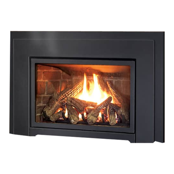
E30I
Gas Insert -
Log Set & Proflame IPI Valve
FOR YOUR SAFETY
Do not store or use gasoline or other flammable
vapours and liquids in the vicinity of this or any
other appliance.
This appliance is only for use with the type of gas
indicated on the rating plate. This appliance is not
convertible for use with other gases, unless a certified
WARNING:
If the information in this manual
is not followed exactly, a fire or explosion
may result causing property damage, personal
injury or loss of life. Installation and service
must be performed by a qualified installer,
service agency or the gas supplier.
O- T L
Tested &
Portland
Listed By
Oregon USA
C
US
OMNI-Test Laboratories, Inc,
Report # 268-S-23-5
Report # 268-S-06b-2
SHERWOOD INDUSTRIES IS AN ENVIRONMENTALLY RESPONSIBLE COMPANY. THIS MANUAL IS PRINTED ON RECYCLED PAPER.
Version Française: www.enviro.com/fr.html
kit is used.
Massachusetts installations (Warning): This product must be installed by a licensed
plumber or gas fitter when installed within the Commonwealth of Massachusetts. Other
Massachusetts code requirements: Flexible connector must not be longer than 36in.,
a shut off valve must be installed; only direct vent sealed combustion products are
approved for bedrooms/bathrooms. A carbon monoxide detector is required in all rooms
containing gas fired direct vent appliances. The fireplace damper must be removed or
welded in the open position prior to installation of a fireplace insert.
PLEASE KEEP THESE INSTRUCTIONS FOR FUTURE REFERENCE
OWNER'S MANUAL
INSTALLER:
Leave this manual with the appliance.
CONSUMER:
Retain this manual for future reference.
WHAT TO DO IF YOU SMELL GAS
• Open windows/extinguish any open
flame.
• Do not try to light any appliance.
• Do not touch any electrical switch
or use any phone in your building.
• Immediately call your gas supplier
from a neighbour's phone. Follow
the gas supplier's instructions.
• If you cannot reach your gas
supplier, call the fire department.
50-2597
Advertisement
Table of Contents
Troubleshooting

Related Manuals for Enviro E30I


Summary of Contents for Enviro E30I
- Page 1 Report # 268-S-06b-2 welded in the open position prior to installation of a fireplace insert. SHERWOOD INDUSTRIES IS AN ENVIRONMENTALLY RESPONSIBLE COMPANY. THIS MANUAL IS PRINTED ON RECYCLED PAPER. PLEASE KEEP THESE INSTRUCTIONS FOR FUTURE REFERENCE 50-2597 Version Française: www.enviro.com/fr.html...
-
Page 2: Safety Precautions
Do not abuse the glass by striking it or slamming the door shut. HOT GLASS WILL • If the E30I unit is pulled out of its installation, and CAUSE BURNS the vent-air intake system is disconnected for any reason, ensure that the vent-air intake pipes are reconnected and... -
Page 3: Table Of Contents
Table of Contents Safety Precautions......................2 Table of Contents......................3 Codes And Approvals.......................4 Specifications........................5 Rating Label Location...................5 Dimensions......................5 E30I Options Dimensions..................6 Operating Instructions.....................7 Lighting and Turning Off Instructions..............7 Venturi Adjustment....................8 Normal Sounds During Operation.................8 Remote Control Operations...................8 Switching to Continuous Pilot Mode................9 Wall Mounting the Receiver.................11... -
Page 4: Codes And Approvals
After the unit has gone through the first burn, turn the unit off, let the unit get cold then remove the glass door and clean it with a good gas fireplace glass cleaner, available at your local ENVIRO dealer. See “D ”... -
Page 5: Specifications
The rating label is located on the bottom of the unit, behind the front access door. imensions 17.89 6.94 6.94 13.73 12.05 27.56 26.56 24.38 21.07 14.06 16.25 19.61 18.65 FRONT 16.49 2.38 LEFT RIGHT 3.07 1.30 15.81 Figure 1: E30I Exterior Dimensions. -
Page 6: E30I Options Dimensions
Specifications 8 " 25" 8 " 8 " Figure 2: E30I Contemporary Surround with Base Shelf and Riser. Table 1: E30I Options Dimensions. Regular Surround Contemporary Surround Extruded Surround Height 25” (635mm) 25” (635mm) 25” (635mm) Width ” (1013 mm) ”... -
Page 7: Operating Instructions
Operating Instructions For Your Safety, Read Safety Precautions And Lighting Instructions Before Operating WARNING: IF YOU DO NOT FOLLOW THESE INSTRUCTIONS EXACTLY A FIRE OR EXPLOSION MAY RESULT, CAUSING PROPERTY DAMAGE, PERSONAL INJURY OR LOSS OF LIFE. ighting anD uRning nstRuctions FOR YOUR SAFETY READ BEFORE OPERATING WARNING:... -
Page 8: Venturi Adjustment
The Proflame GTM is a modular remote control system that directs the functions of the E30I. The Proflame GTM is configured to control the on/off main burner operation, its flame levels and provides on/ off and Smart thermostatic control of the appliance. -
Page 9: Switching To Continuous Pilot Mode
Operating Instructions Operating Instructions ATTENTION! - TURN “OFF” THE MAIN GAS SUPPLY OF THE APPLIANCE DURING INSTALLATION OR MAINTENANCE OF THE RECEIVER. - PLACE THE RECEIVER’S 3 POSITION SLIDER SWITCH IN THE “OFF” POSITION DURING INSTALLATION OR MAINTENANCE. - TURN “OFF” MAIN GAS SUPPLY TO THE APPLIANCE PRIOR TO REMOVING OR REINSERTING THE BATTERIES IN THE RECEIVER. - Page 10 Operating Instructions TRANSMITTER (Remote Control with LCD Display) The Proflame Transmitter uses a streamline design with a simple button layout and informative LCD display (Figure 5). The Transmitter is powered by three (3) AAA type batteries. A Mode Key is provided to Index between the features and a Thermostat Key is used to turn on/off or index through Thermostat functions (Figure 5 &...
-
Page 11: Wall Mounting The Receiver
Operating Instructions emote ounting eceiVeR ptionaL The receiver can be removed from the unit and placed inside a standard Junction type wall box or another convenient location. This installation can take place up to 6’ft (1.8 m) from the appliance control valve. 1. - Page 12 Operating Instructions Turn off the Appliance Room Temperature Press the ON/OFF Key on the Transmitter. The Transmitter LCD display will only show the room temperature and Icon (see Figure 11). A single “beep” from the Receiver confirms reception of the command and both the pilot light (if the unit is not set to continuous pilot) and main burner will turn off.
- Page 13 Operating Instructions Key lock This function will lock the keys to avoid unsupervised operation. To activate this function, press the MODE and UP keys at the same time and the a lock will appear (see Figure 15). To de-activate this function, press the MODE and UP Keys at the same time.
-
Page 14: Maintenance And Service
The glass must be purchased from an ENVIRO dealer. No substitute materials are allowed. Remove the door (see page 15). The replacement glass will come with a new gasket installed. Remove any silicone remnants from the door. -
Page 15: Glass Door Removal
Maintenance And Service Lass emoVaL Figure 18: Door Release. Figure 19: Door Removal. Remove the glass door by placing the hooked end of the door release tool in the hole on the door latch mechanism (see Figure 18) and pulling the latch out then up. When the two (2) latches have been released, tilt the bottom of the door forward and then lift up to unhook the top door tabs (see Figure 19). -
Page 16: Removing Valve Cover
Maintenance And Service emoVing aLVe oVeR The valve cover can be removed to access the gas valve. 1. Remove the glass door as shown in m aIntenance anD erVIce lass emoVal 2. Remove the liners and burner. Refer to s econDary nstallatIon Irebox... -
Page 17: Fuel Conversion
Fuel Conversion TO BE INSTALLED BY A QUALIFIED SERVICE AGENCY ONLY Please read and understand these instructions before installing. WARNING: This conversion kit shall be installed by a qualified service agency in accordance with the manufacturer’s instructions and all applicable codes and requirements of the authority having jurisdiction. - Page 18 Fuel Conversion 10. Reinstall the burner, brick panels, log set, embers, and glass door. Also refer to s econDary nstallatIon in your Owner’s Manual. When re-installing the burner, ensure that nstallIng et anD mbers the burner to pilot hood relationship is similar to what is shown in Figure 21. 11.
-
Page 19: Initial Installation
The vent length for the E30I must be between 8ft (2.44 m) and 30ft (9.14 m). This model is vented with a 3” intake and a 3” exhaust aluminum or stainless steel flex vent leading into a vertical termination cap. -
Page 20: Venting Fireplace Inserts
Check for any tears in the liner at this point. IMPORTANT: The screws that hold the vent collar plate in its approved position must be installed. NOTE: If the E30I unit is pulled out of its installation, and the vent air intake system is disconnected for any reason, ensure that the vent-air intake pipes are re-sealed with high-temperature sealant and reconnected with three (3) sheet metal screws evenly spaced. - Page 21 (either silicone or stove cement). The flue damper can be fully blocked open or removed for installation of the E30I; the smoke shelves, shields and baffles may be removed if attached by mechanical fasteners. The fireplace and fireplace chimney must be clean, in good working order and constructed of non-combustible materials.
-
Page 22: Direct Vent Vertical Vent Termination
1. Plan your installation and clearances to combustibles. The E30I may be installed and vented into any solid fuel fireplace that has been installed in accordance with the National, Provincial/State and local building codes and has been constructed of non-combustible materials. Also refer to the I... -
Page 23: Installing The Unit
4. Check that the chimney clean outs fit properly. The flue damper must be fully blocked open or removed for installation of the E30I; the smoke shelves, shields and baffles may be removed if attached by mechanical fasteners. -
Page 24: Zero Clearance Fireplace Installation
Initial Installation QUALIFIED INSTALLERS ONLY (zc) f LeaRance iRepLace nstaLLation The metal floor of the ZC solid fuel firebox can be removed to allow the installation of the insert. THE CLEARANCE TO COMBUSTIBLE MATERIAL UNDER THE INSERT IS 2 ” (57.2 mm). YOU MUST USE THE LEVELING LEGS TO RAISE THE INSERT A MINIMUM OF 2 ”... - Page 25 Initial Installation QUALIFIED INSTALLERS ONLY Figure 30: Wiring Schematic.
- Page 26 ½ psi (3.5 kPa). Figure 32: Gas Valve with Cover Removed. Table 5: Orifice and Pressure Information. E30I With Log Set & Proflame Valve Main Burner Natural Gas Propane Gas Orifice:...
- Page 27 Initial Installation QUALIFIED INSTALLERS ONLY TO TEST VALVE PRESSURES (INPUT RATES): The pressure taps are located on the front side of the valve (see Figure 33). 1. Using a long flat bladed screwdriver, turn set screw counter-clockwise to loosen. 2. Place in (8 mm) I.D.
-
Page 28: Adjusting The Pilot Flame
Initial Installation QUALIFIED INSTALLERS ONLY Djusting iLot Lame The pilot flow adjustment is set to maximum at the factory and should not need to be adjusted. The pilot flame should envelope ⅜” to ½” (10 to 13mm) of the thermocouple (see Figure 34). However, should the need arise, follow Steps 1- 2 below. -
Page 29: Secondary Installation
The E30I Base Shelf (1⅝” (41 mm) high) and Base Shelf Riser (2⅛” (54 mm) high) are components that can be combined to create a riser with an overall height of 2 ” (55 mm). This shelf can be installed with or without the riser and can be used when the hearth in front of the unit is lower than the fireplace opening. -
Page 30: Optional Trimmable Panel
Modifying the Surround Panel: The E30I Trimmable Surround Panels are large rectangular panels that may be cut for use in cases that a non- standard fireplace opening (e.g. an arched opening) is to be filled. Optionally this surround can be left uncut and placed in front of the fireplace opening. -
Page 31: Surround Panel Installation
Every surround panel comes with a burner switch and wires already installed. Because the E30I is completely remote controlled, there is no need for a burner switch. A blank filler switch is included in the E30I manual bag and can be installed in the panel in place of the burner switch/wires. -
Page 32: Firebox Liner And Burner Tube Removal / Installation
WARNING: Failure to position the parts in accordance with these diagrams or failure to use only parts specifically approved with this appliance may result in property damage or personal injury. 1. Ensure the E30I is turned off and allow the unit to cool. 2. Remove the glass door as shown in the m... -
Page 33: Log Set And Ember Removal / Installation
Secondary Installation et anD mbeR nstaLLation NOTE: The logs are fragile and should be handled gently. WARNING: Failure to position the parts in accordance with these diagrams or failure to use only parts specifically approved with this appliance may result in property damage or personal injury. - Page 34 Secondary Installation Figure 52: Place the log grate in front of the burner tube using the two slotted mounts underneath. Figure 52. Third Stage Log Set Installation. Figure 53: The ember wool comes in chunks that can be ripped into smaller pieces.
- Page 35 Secondary Installation Figure 55: Place the small left and right logs as shown. The bottoms of both pieces have contours to fit on the log grate. Figure 55. Sixth Stage Log Set Installation. Figure 56: Place the two center logs as shown.
-
Page 36: Troubleshooting
TroubleShooting iagnostic Lash oDes 1. Fail to ignite: If there is no positive ignition, the board will go into lock out and the LED will blink 3 times in intervals until the system is reset. 2. Low battery condition (<4V): the LED indicator will blink one (1) time in intervals. 3. -
Page 37: Troubleshooting
TroubleShooting Problem Possible Cause Solution The pilot flame has gone out Thermostat · Turn it ON does not The On/Off switch is turn to OFF work The thermostat is set too high · Set the thermostat to a lower temperature ·... - Page 38 TroubleShooting Problem Possible Cause Solution · Turn the system off by pressing the ON/OFF button on the transmitter · After approximately 2 seconds press the ON/OFF button on the transmitter again. · In the manual flame control mode, use the down arrow button to reduce the flame to off, indicated by the word OFF displayed on the transmitter LCD screen.
-
Page 39: Parts List
Burner Control Module 50-2781 PSE IPI Pilot Assembly 50-2547 Remote Receiver 50-2007 E30I Owners Manual 50-2597 E30I Conversion Kit NG to LP 50-2486 E30I Conversion Kit LP to NG 50-2541 Ceramic Wool Embers Only 50-893 E30 Logset (9 Pcs.) 50-2508... - Page 40 Parts List Reference Option Description Part Number Number Regular Surround Panel 50-2418 Contemporary Surround Panel 50-2419 Extruded Surround Panel 50-2420 Trim-able Surround Panel 50-2422 Base Shelf 50-2424 Base Shelf Riser 50-2425 Four Sided Surround 50-2484 Four Sided Trimmable Panel 50-2485 Safety Screen 50-2495 Oversized Contemporary Surround Panel...
-
Page 41: Parts Diagram - Components
Parts Diagram - Components... -
Page 42: Parts Diagram - Options
Parts Diagram - Options... -
Page 43: Warranty
Exclusions conditions herein set forth, this product against defects in material and workmanship An expanded list of exclusions is available at www.enviro.com/help/warranty.html during the specified warranty period starting from the date of original purchase at retail. This warranty does not cover: In the event of a defect of material or workmanship during the specified warranty period, ƒ... -
Page 44: Installation Data Sheet
� NATURAL GAS (NAT) PROPANE(LPG) _________________________________________ INLET GAS PRESSURE:_________in WC PHONE:___________________________________ MAIN BURNER ORIFICE:__________# DMS PILOT ORIFICE #_________OR________in diam. INSTALLER’S SIGNATURE: _________________________________________ MANUFACTURED BY: SHERWOOD INDUSTRIES LTD. 6782 OLDFIELD RD. SAANICHTON, BC, CANADA V8M 2A3 www.enviro.com December 30, 2013 C-13797...
Need help?
Do you have a question about the E30I and is the answer not in the manual?
Questions and answers