Table of Contents
Advertisement
Quick Links
Advertisement
Table of Contents

Related Manuals for Contec BX-100n-DC5000-C01


Summary of Contents for Contec BX-100n-DC5000-C01
- Page 1 IPC Series BOX-PC for BX100n Series User’s Manual CONTEC CO.,LTD.
- Page 2 Notes on using Windows Embedded None None Standard Recovery Media *2 None *1 It is attached to the main body. *2 Please confirm latest information on the CONTEC homepage though the manual is stored in Recovery Media (\MANUAL). BX-100n User’s manual...
-
Page 3: Copyright
No part of this document may be copied or reproduced in any form by any means without prior written consent of CONTEC CO., LTD. CONTEC CO., LTD. makes no commitment to update or keep current the information contained in this document. -
Page 4: Table Of Contents
Table of Contents Check your package ..........................i Copyright ..............................ii Trademarks ..............................ii Table of Contents ...........................iii INTRODUCTION About the Product ........................... 1 Features............................. 2 Supported OS ........................... 3 Support Software (Model with multi-signal I/O) ................4 Customer Support............................ 5 Web Site ............................5 Limited One-Year Warranty ........................ - Page 5 EACH COMPONENT FUNCTION Component Name ..........................27 Front View ............................27 Side View............................27 Back View............................27 System Configuration ..........................29 Component Function ..........................30 LED: POWER, ACCESS, STATUS .....................30 DC Power Input Connector : DC-IN .....................30 POWER SW ...........................31 Line out Interface : LINE OUT......................31 MIC in Interface : MIC ........................31 Serial-ATA : S-ATA1 - 2.......................31 Giga bit-Ethernet : LAN 1 –...
- Page 6 Advanced Chipset Features Setup ......................70 PCI Express Root Port Function......................73 VGA setting............................74 Watch Dog Timer Setting ........................75 Integrated Peripherals ........................... 76 OnChip IDE Device ..........................77 On Chip Serial ATA setting........................80 Onboard Device............................. 82 Super IO Device ............................ 85 Power Management Setup ........................
- Page 7 APPENDIX Memory Map ............................117 I/O Port Addresses..........................118 Interrupt Level List..........................119 POST Codes............................120 COM I/O Address and Register Function...................125 Watch-Dog-Timer..........................131 LIST OF OPTIONS BX-100n User’s manual...
-
Page 8: Introduction
Embedded-type CPU and chip set have been adopted. The use of readily available parts ensures the ease of the use of the product. In addition, the use of a Contec-customized BIOS allows support to be provided at the BIOS level. -
Page 9: Features
< Model with multi-signal I/O > Immediate measurement control enabled by internal analog I/O, digital I/O, and counter input features It contains analog I/O, digital I/O, and counter input features equivalent to CONTEC's measurement control boards (AIO-163202F-PE, DIO-1616L-PE, CNT-3204MT-LPE). A set of this product features measurement control that can measure voltage, detect location, etc. -
Page 10: Supported Os
1. Introduction Remote power management function to reduce operation tasks This product supports timed/automated system start-up (Resume By Alarm). For example, it enables unattended operation, such as starting to show information of an establishment in unison at opening time. Also, it supports system start-up externally via network (Wake On LAN) and modem (Power On by Ring). It encourages significant labor saving in operation. -
Page 11: Support Software (Model With Multi-Signal I/O)
1. Introduction Support Software (Model with multi-signal I/O) You should use CONTEC support software according to your purpose and development environment. Windows version of analog I/O driver API-AIO(WDM) [Installed on the main body] These drivers are the Windows version of analog I/O driver library software that provides products in the form of Win32 API functions (DLL). -
Page 12: Customer Support
You can download updated driver software and differential files as well as sample programs available in several languages. Note! For product information Contact your retailer if you have any technical question about a CONTEC product or need its price, delivery time, or estimate information. Limited One-Year Warranty CONTEC products are warranted by CONTEC CO., LTD. -
Page 13: Safety Precautions
1. Introduction Safety Precautions Understand the following definitions and precautions to use the product safely. Safety Information This document provides safety information using the following symbols to prevent accidents resulting in injury or death and the destruction of equipment and resources. Understand the meanings of these labels to operate the equipment safely. - Page 14 To prevent corruption of files, always shutdown the OS before turning off this product. CONTEC reserves the right to refuse to service a product modified by the user. In the event of failure or abnormality (foul smells or excessive heat generation), unplug the power cord immediately and contact your retailer.
- Page 15 1. Introduction BX-100n User’s manual...
-
Page 16: System Reference
Serial ATA I/F 2.5 inch SATA hard disk slot-in system x None 2, Corresponding to RAID 0.1, serial ATA 1.0 standard port BX-100n-DC5000-C01 : -, None BX-100n-DC5121-C01 : HDD1 is finished mounting SATA HDD. (40GB, 1 partition) CF card slot... - Page 17 *4 : For more details on this, refer to the manual for CONTEC’s analog I/O board AIO-163202F-PE. *5 : For more details on this, refer to the manual for CONTEC’s digital I/O board DIO-1616L-PE. *6 : For more details on this, refer to the manual for CONTEC’s up down counter board CNT-3204MT-LPE. BX-100n User’s manual...
- Page 18 2. System Reference Table 2.1. Functional Specification < 3 / 3 > BX-100n-DC5000-C01 BX-100n-DC5000-C02 Model BX-100n-DC5121-C01 *1 BX-100n-DC5311-C02 Hardware monitoring Monitoring CPU temperature, board temperature, power voltage Watch dog timer Software programmable, 255 level (1sec - 255 sec) Causes a reset upon time-out.
- Page 19 2. System Reference Table 2.2. Installation Environment Requirements BX-100n-DC5000-C01 BX-100n-DC5000-C02 Model BX-100n-DC5121-C01*1 BX-100n-DC5311-C02 Operating temperature 0 - 50°C *11 0 - 45°C *10 Storage temperature -10 - 60°C Humidity 10 - 90%RH (No condensation) Floating dust particles Not to be excessive...
-
Page 20: Power Management Features
2. System Reference Power Management Features Support both ACPI (Advanced Configuration and Power Interface) and legacy (APM) power management. ACPI v2.0 compliant APM v1.2 compliant PCI bus clock run, Power Management Enable (PME) control, all with hardware automatic wake-up Multiple suspends power plane controls and suspends status indicators Normal, doze, suspend and conserve modes Global and local device power control Power Requirements... -
Page 21: Physical Dimensions
2. System Reference Physical Dimensions BX-100n-DC5xxx-C01 M3 screws *2 8-φ5 M3 screws *1 [mm] Surface of the cabinet *1 : When you fasten the bundled attachment fittings to be fixed to the body, you should use the attached screws (M3 x 8). Otherwise, the length (L) from the surface of the cabinet to the screw tip should be 6mm or less. - Page 22 2. System Reference BX-100n-DC5xxx-C02 M3 screws *2 8-φ5 [mm] M3 screws *1 Surface of the cabinet *1 : When you fasten the bundled attachment fittings to be fixed to the body, you should use the attached screws (M3 x 8). Otherwise, the length (L) from the surface of the cabinet to the screw tip should be 6mm or less.
- Page 23 2. System Reference BX-100n User’s manual...
-
Page 24: Hardware Setup
3. Hardware Setup 3. Hardware Setup Before Using the Product for the First Time Follow the next steps to set up this product : STEP1 By referring to the information in this chapter, install, connect and set this product. STEP2 Connect cables. -
Page 25: Hardware Setup
3. Hardware Setup Hardware Setup Before you start, be sure that the power is turned off. Remove only those screws that are explained. Do not move any other screw. Attaching the CF Attachment Fittings (1) After inserting a CF Card, fasten the bundled CF attachment fittings with a screw. Figure 3.1. -
Page 26: Attaching The Fg
3. Hardware Setup Attaching the FG (1) Use screws to attach the FG. Attached screw (M3 x 8) Figure 3.3. Attaching the FG CAUTION The FG pin of this product is connected to the GND signal of the DC power connector (DC-IN). Note that the connection cannot be cut off. -
Page 27: Installing The Hard Disk
3. Hardware Setup (2) The photo below shows an example of using a cable clamp. Fix the cable with a clamp without applying stress to the connector. Figure 3.5. Using example of cable clamp Installing the Hard Disk BX-100n-DC5xxx-C01 can incorporate 2.5-inch SATA hard disk on a slot-in basis. <... -
Page 28: Installation Requirements
3. Hardware Setup Installation Requirements Be sure that the ambient temperature is within the range specified in the installation environment requirement by making space between the product and device that generates heat or exhaust air. BX-100n-DC5xxx-C01 Installable directions at operating temperature 0 - +45°C : All type of installation (including diagonal installation) CAUTION To use 1000BASE-T, you should keep its ambient temperature between 0 - 40°C... - Page 29 3. Hardware Setup BX-100n-DC5xxx-C02 Installable directions at operating temperature 0 - +50°C : All type of installation (including diagonal installation) CAUTION To use 1000BASE-T, you should keep its ambient temperature between 0 - 45°C Operating temperature : 0 - +50 ° C (When using the 1000BASE-T : 0 - +45 °...
- Page 30 3. Hardware Setup Distances between this product and its vicinity BX-100n-DC5xxx-C01 100 mm 100 mm or more or more 50mm more Figure 3.9. Distances between this product and its vicinity < BX-100n-DC5xxx-C01 > CAUTION Do not install this product into the fully-sealed space except the case in which the internal temperature is adjustable by equipment such as air conditioner.
- Page 31 3. Hardware Setup BX-100n-DC5xxx-C02 100 mm 100 mm or more or more 50mm more Figure 3.10. Distances between this product and its vicinity < BX-100n-DC5xxx-C02 > CAUTION Do not install this product into the fully-sealed space except the case in which the internal temperature is adjustable by equipment such as air conditioner.
- Page 32 3. Hardware Setup Ambient temperature In this product, the ambient temperature is decided from the multiple measurement points as shown below. When making use of the product, the air current should be adjusted to prevent that all the temperatures measured at the measurement points exceed the specified temperature. BX-100n-DC5xxx-C01 <Vertical installation>...
- Page 33 3. Hardware Setup BX-100n User’s manual...
-
Page 34: Each Component Function
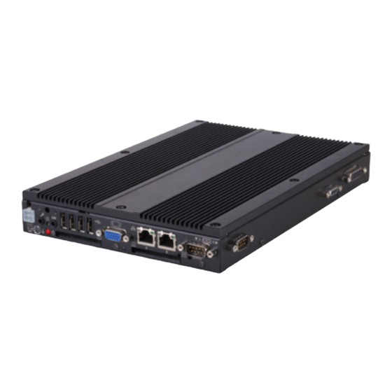
4. Each Component Function 4. Each Component Function Component Name Front View BX-100n-DC5xxx-C01, BX-100n-DC5xxx-C02 LINE POWER DVI-I STATUS 12 - 24 STATUS DC-IN LAN1 LAN2 SERIAL1 ACCESS LED POWER Figure 4.1. Component Name < 1 / 3 > Side View BX-100n-DC5xxx-C01 Left side Right side... - Page 35 4. Each Component Function Table 4.1. Component Function Name Function POWER-SW Power switch POWER LED Power ON display LED ACCESS LED IDE disk access display LED STATUS LED Status LED S-ATA LED S-ATA disk access display LED *1 DC-IN DC power input connector Line out ( φ...
-
Page 36: System Configuration
4. Each Component Function System Configuration BX-100n-DC5xxx-C01 USB2.0 LINE OUT FD drive EXPANDER (PCIe) Printer SERIAL port CF card (1,2) Display USB device such LAN port as CD-ROM drive (1,2) .,etc Figure 4.2. System Configuration < BX-100n-DC5xxx-C01 > BX-100n-DC5xxx-C02 USB2.0 LINE OUT FD drive EXPANDER... -
Page 37: Component Function
Indicates that the S-ATA device is being accessed. API that controls STATUS LED is available. See the API description file "mtdll_e.chm" included in /RasUtility/Samples in the CONTEC’s Web site [IPC-SLIB-01] for details. DC Power Input Connector : DC-IN To supply the power, always use the power supply listed below. -
Page 38: Power Sw
The audio driver is required to use the microphone input and line output interfaces. Install the appropriate audio driver for your OS from the CONTEC’s Web site CD-ROM [IPC-SLIB-01]. (For information on the latest version of IPC-SLIB-01, check the CONTEC's Web site.) Serial-ATA : S-ATA1 - 2 This product is equipped with the serial-ATA 1.0-compliant controller, allowing a 2.5-inch SATA hard... -
Page 39: Giga Bit-Ethernet : Lan 1 - 2
10M : Off, 100M : Green, 1000M : Orange LAN drivers Install the appropriate audio driver for your OS from the CONTEC’s Web site [IPC-SLIB-01]. (For information on the latest version of IPC-SLIB-01, check the CONTEC's web site.) CAUTION Attention should to be paid to the guaranteed operating range of temperature in using 1000BASE-T. -
Page 40: Serial Port Interface : Serial1 - 5
4. Each Component Function Serial Port Interface : SERIAL1 - 5 SERIAL1, 2, 3, 4, 5 (RS-232C Ports) The product has 5 channels of RS-232C compliant serial ports supporting up to a baud rate of 115,200bps with a 16-byte transmission-dedicated data buffer and a 16-byte reception-dedicated data buffer. You can use “Chapter 5 BIOS Setup”... - Page 41 4. Each Component Function Table 4.8. RS-422/485 Port Connector (Inside the RAS Connector) Pin No. Signal name Meaning TX + Transmitted data + TX - Transmitted data - RX + Received data + RX - Received data - Reference For more information on the RAS connector see Table 4.12, "RAS connector". RS-422/RS-485 Specifications Transmission method : RS-422/RS-485-compliant, asynchronous, serial transmission, half...
-
Page 42: Dvi Interface : Dvi
A DVI interface is provided. You can use it to connect a CRT (even a D-SUB 15 pin connector is acceptable by using the bundled DVI-analog RGB adapter) or a CONTEC Panel Link display. The connector is named DVI (DVI-I 29-pin connector). - Page 43 For the LCDs that can be connected, please refer to “Chapter 8 List of Options”. Display driver Install the appropriate audio driver for your OS from the CONTEC’s Web site [IPC-SLIB-01]. (For information on the latest version of IPC-SLIB-01, check the CONTEC's Web site.)
-
Page 44: Cf Card Connector (Primary Ide Connection) : Cf1 - 2
4. Each Component Function CF Card Connector (Primary IDE Connection) : CF1 - 2 The CF Card (Type I : dedicated to the memory card) can be connected. Before you insert/remove the CF card, make sure that the power is switched off and the access LED is turned off. -
Page 45: Ras Functions : Ras
4. Each Component Function RAS Functions : RAS A RAS port is provided for the BX-100n-DC5xxx-C01. This port offers watchdog timer, remote reset, and general-purpose I/O RAS functions. Table 4.12. RAS Connector Connector type 15pin D-SUB (FEMALE) No.4-40UNC Inch screw threads Pin No. -
Page 46: Watchdog Timer
4. Each Component Function Watchdog Timer The watchdog timer is started by output of A5 to I/O port address 4002h. A second output of A5 to the same port within the specified expiration time once again triggers the watchdog timer. If a time-out occurs, a reset or an interrupt is generated according to the 4004h port setting or an alarm is output according to the 4004h port setting. - Page 47 4. Each Component Function How to Use the Watchdog Timer BIOS setting Power ON Set event Output data to ports 4001h and 4004h to set the counter clock. output control Instruct WDT Read port 4002h, stop the WDT, and turn off alarm output. to stop Set timer value Output set data to port 4003h.
- Page 48 4. Each Component Function * 4001h (bit4-6): Alarm out output control WD_S1 WD_S0 PO2_M RESET PIM2 PIM1 PIM0 R/W (Default: XXXX0000b) Figure 4.6. Alarm Out Output Control Port (4001h) PO2_M : PO PO2/WDT pin output setting : Set the RAS connector's PO2/WDT(12) signal to PO2 (general-purpose output). : Set the RAS connector's PO2/WDT(12) signal to alarm out.
- Page 49 4. Each Component Function * 4004h : Event output control RESET R/W (Default: XXXX0000b) Figure 4.9. Event Output Control Port (4004h) Table 4.14. WM2-WM0: Interrupt Output Modes Interrupt output at occurrence of WDT errors Output to IRQ5 when time expires on the WDT. Output to IRQ7 when time expires on the WDT.
-
Page 50: General-Purpose I/O And Remote Reset
4. Each Component Function General-purpose I/O and Remote Reset The BOX-PC is equipped with three general-purpose insulated signals each for input and output. The input signals can also be used for interrupt input or remote reset input. Specifications [ Input ] Input specifications Current-driven input by Optocoupler isolation Input resistance... - Page 51 4. Each Component Function I/O Addresses and Instructions * 4000h: General-purpose I/O PIO2 PIO1 PIO0 Figure 4.12. General-purpose Input Port (4000h) R : Read data from PI0, PI1 and PI2. W : Set data to be output to PO0, PO1 and PO2. * 4001h (bit0-3): PI2/IRQ(14) event input control WD_S1 WD_S0...
- Page 52 4. Each Component Function * 4007h: Control of RS-485 transmission and reception RE_GATE TE_GATE TE_SEL rsv* (Default: XXXX0000b) Figure 4.14. RS-485 Transmission and Reception Control Port (4007h) TE_SEL Select the RS-485 transmission enable signal. Sets the RTS signal to the RS-485 transmission enable signal. (factory setting) Sets the TE_GATE value to the RS-485 transmission enable signal.
- Page 53 4. Each Component Function 0 : Controlled by RTS TE_SEL 1 : Controlled by TE_GATE 0 :Transmission prohibited 1 :Transmission permitted 0 :Transmission RX-(11) permitted TE_GATE RX+(3) 1 :Transmission TX-(10) prohibited 0 :Receiving TX+(2) permitted RE_GATE 1 :Receiving prohibited 120k Ω RS485 Terminator Enabled : On Control...
-
Page 54: Bus Expander (Pcie)
BUS EXPANDER (PCIe) This product is equipped with the PCI Express cable port. You can use CONTEC's abundant measurement control boards by connecting with our PCI Express Cable-based expansion chassis and CB-CE-1, the cable for Cable Express at extra cost. -
Page 55: Aio
96pin half pitch connector [M (male) type] PCR-96LMD [HONDA TSUSHIN KOGYO CO.,] or equivalence to it Connector pin assignment is compatible with that of CONTEC's AIO-163202F-PE. - The numbers in square brackets [ ] are pin numbers designated by HONDA TSUSHIN KOGYO CO.,... - Page 56 4. Each Component Function Analog input signal. Analog Input00 - Analog Input31 The numbers correspond to channel numbers. Analog output signal. Analog Output00 - Analog Output01 The numbers correspond to channel numbers. Analog Ground Common analog ground for analog I/O signal. AI External Start Trigger Input External trigger input signal for starting analog input sampling.
- Page 57 96pin half pitch connector [M (male) type] PCR-96LMD [HONDA TSUSHIN KOGYO CO.,] or equivalence to it Connector pin assignment is compatible with that of CONTEC's AIO-163202F-PE. - The numbers in square brackets [ ] are pin numbers designated by HONDA TSUSHIN KOGYO CO.,...
- Page 58 4. Each Component Function Analog input signal. Analog Input00 - Analog Input15 The numbers correspond to channel numbers. Analog output signal. Analog Output00 - Analog Output01 The numbers correspond to channel numbers. Analog Ground Common analog ground for analog I/O signals. AI External Start Trigger Input External trigger input signal for starting analog input sampling.
-
Page 59: Dio
37pin D-SUB connector [F (Female) type] DCLC-J37SAF-20L9E [mfd.by JAE] or equivalence to it Connector pin assignment is compatible with that of CONTEC's DIO-1616L-PE. I-00 - I-17 16 input signal pins. Connect output signals from the external device to these pins. -
Page 60: Cnt
68pin 0.8mm pitch connector HDRA-E68LFDT+ [HONDA TSUSHIN KOGYO CO.,] or equivalence to it Connector pin assignment is compatible with that of CONTEC's CNT-3204MT-LPE. The control input can serve as the general-input, counter start / stop, preset and zero-clear. The control output can serve as the general-output, count match, abnormal input error and digital filter error. - Page 61 4. Each Component Function BX-100n User’s manual...
-
Page 62: Bios Setup
5. BIOS Setup 5. BIOS Setup Introduction This chapter discusses Award’s Setup program built into the FLASH ROM BIOS. The Setup program allows users to modify the basic system configuration. This special information is then stored in battery-backed RAM so that it retains the Setup information when the power is turned off. The rest of this chapter is intended to guide you through the process of configuring your system using Setup. -
Page 63: Using Setup
5. BIOS Setup Using Setup In general, you use the arrow keys to highlight items, press <Enter> to select, use the PageUp and PageDown keys to change entries, press <F1> for help and press <Esc> to quit. The following table provides more detail about how to navigate in the Setup program using the keyboard. -
Page 64: Main Menu
5. BIOS Setup Main Menu Once you enter the Award BIOS CMOS Setup Utility, the Main Menu will appear on the screen. The Main Menu allows you to select from several setup functions and two exit choices. Use the arrow keys to select among the items and press <Enter>... - Page 65 5. BIOS Setup PnP / PCI Configuration This entry appears if your system supports PnP / PCI. Load Fail-Safe Defaults Use this menu to load the BIOS default values for the minimal/stable performance for your system to operate. Load Optimized Defaults Use this menu to load the BIOS default values that are factory settings for optimal performance system operations.
-
Page 66: Standard Cmos Setup
5. BIOS Setup Standard CMOS Setup Figure 5.2. Standard CMOS Setup The items in Standard CMOS Setup Menu are divided into 10 categories. Each category includes no, one or more than one setup items. Use the arrow keys to highlight the item and then use the <PgUp> or <PgDn>... -
Page 67: Main Menu Selections
5. BIOS Setup Main Menu Selections This table shows the selections that you can make on the Main Menu. Table 5.2. Main Menu Selections Item Options Description Set the system date. Note that the ‘Day’ Date Month DD YYYY automatically changes when you set the date Time HH : MM : SS... -
Page 68: Ide Adapters
5. BIOS Setup IDE Adapters The IDE adapters control the CF card. Use a separate sub menu to configure each CF card. Use the legend keys to navigate through this menu and exit to the main menu. Use Table 5.3 to configure the hard disk. -
Page 69: Advanced Bios Features Setup
5. BIOS Setup Advanced BIOS Features Setup This section allows you to configure your system for basic operation. You have the opportunity to select the system’s default speed, boot-up sequence, keyboard operation, shadowing and security. CPU Feature [Press Enter] Item Help Hard Disk Boot Priority [Press Enter] Virus Warning... -
Page 70: Cpu Feature
5. BIOS Setup CPU Feature Figure 5.4. CPU Feature Press <Enter> to configure the settings relevant to CPU Feature. Table 5.4. CPU Features Selections Description Choice Delay Prior to Thermal Select the interval to setup the delay timer for CPU Thermal-Throuttling C1E Function CPU C1E Function Select. -
Page 71: Hard Disk Boot Priority
5. BIOS Setup Description Choice Execute Disable Bit When disabled, forces the XD feature flag to always return Hard Disk Boot Priority Figure 5.5. Hard Disk Boot Priority With the field, there is the option to choose, aside from the hard disks connected, “Bootable add-in Cards”... -
Page 72: Virus Warning
5. BIOS Setup Virus Warning When enabled, you receive a warning message if a program (specifically, a virus) attempts to write to the boot sector or the partition table of the hard disk drive. You should then run an anti-virus program. Keep in mind that this feature protects only the boot sector, not the entire hard drive. - Page 73 5. BIOS Setup Description Choice Quick Power On Self Test Select Enabled to reduce the amount of time required to run the power-on self-test (POST). A quick POST skips certain steps. We recommend that you normally disable quick POST. Better to find a problem during POST than lose data during your work USB Device Wait When USB devices, which need longer time to be booted, are...
-
Page 74: Bx-100N User's Manual
5. BIOS Setup Description Choice Second Boot Device The BIOS attempts to load the operating system from the devices in the sequence selected in these items. Third Boot Device The BIOS attempts to load the operating system from the devices in the sequence selected in these items. Boot Other Device The BIOS attempts to load the operating system from the devices in the sequence selected in these items. - Page 75 5. BIOS Setup Description Choice Gate A20 option Gate A20 refers to the way the system addresses memory above 1 MB (extended memory). When set to Fast, the system chipset controls Gate A20. When set to Normal, a pin in the keyboard controller controls Gate A20.
- Page 76 5. BIOS Setup Description Choice Security Option Select whether the password is required every time the system boots or only when you enter setup. If you have set a password, select whether the password is required every time the System boots, or only when you enter Setup. System: The system will not boot and access to Setup will be denied if the correct password is not entered at the prompt.
-
Page 77: Advanced Chipset Features Setup
5. BIOS Setup Advanced Chipset Features Setup Figure 5.6. Advanced Chipset Features Setup This section allows you to configure the system based on the specific features of the installed chipset. This chipset manages bus speeds and access to system memory resources, such as DRAM and the external cache. - Page 78 5. BIOS Setup Description Choice CAS Latency Time When synchronous DRAM is installed, the number of clock cycles of CAS latency depends on the DRAM timing. Do not reset this field from the default value specified by the system designer. You can select CAS latency time in HCLK of 3/4/5/6 or Auto.
- Page 79 5. BIOS Setup Description Choice System Memory Frequency This item sets the main memory frequency. When you use an external graphics card, you can adjust this to enable the best performance for your system. SLP_S4# Assertion Width Allows you to set the SLP_S4# assertion width. The default setting is 1 to 2 Sec.
-
Page 80: Pci Express Root Port Function
5. BIOS Setup PCI Express Root Port Function Figure 5.7. PCI Express Root Port Function Table 5.7. PCI Express Root Port Function Selections Description Choice PCI Express Port 1/2/3/4/5/6 This item allows you to enable or disable or Auto configure the PCI Express Port 1/2/3/4/5/6. -
Page 81: Vga Setting
5. BIOS Setup VGA setting The field under the On-Chip VGA Setting and their defaults settings are: Table 5.8. VGA Setting Selections Description Choice On-Chip Frame Buffer Size When Enabled, a fixed VGA frame buffer from A000h to BFFFh and a CPU-to-PCI write buffer are implemented. DVMT Mode Allows you to set the Dynamic Video Memory Technology (DVMT) mode. -
Page 82: Watch Dog Timer Setting
5. BIOS Setup Watch Dog Timer Setting Output settings for PO2 of the watchdog timer in RAS port Description Choice WDT Output to PO2 Set watchdog timer output to PO2. Selecting "Enabled" connects the output of the watchdog timer to the PIO2 pin in the RAS connector. The output value changes depending on the "WDT Power-on State"... -
Page 83: Integrated Peripherals
5. BIOS Setup Integrated Peripherals This section sets configurations for your hard disk and other integrated peripherals. The first screen shows three main items for user to select. Once an item selected, a submenu appears. Details follow. Figure 5.8. Integrated Peripherals BX-100n User’s manual... -
Page 84: Onchip Ide Device
5. BIOS Setup OnChip IDE Device Figure 5.9. OnChip IDE Device Table 5.9. On Chip IDE Device Selections Description Choice HDD Select You can choose your CF card type to Auto Select or UDMA BX-100n User’s manual... - Page 85 5. BIOS Setup Description Choice IDE HDD Block mode Block mode is also called block transfer, multiple commands, or multiple sectors read/write. If your IDE hard drive supports block mode (most new drives do), select Enabled for automatic detection of the optimal number of block read/writes per sector the drive can support.
- Page 86 5. BIOS Setup Description Choice IDE Primary Master / Slave PIO The two IDE PIO (Programmed Input/Output) fields let you set a PIO mode (0-4) for the one IDE device that the onboard IDE interface supports. In Auto mode, the system automatically determines the best mode for the device.
-
Page 87: On Chip Serial Ata Setting
5. BIOS Setup On Chip Serial ATA setting Table 5.10. On Chip Serial ATA Setting Selection Description Choice SATA Mode You can set SATA hard disk mode in IDE, AHCI or RAID mode. On-Chip Serial ATA Disabled : Disable SATA controller. Combined Mode : Enable the combination of SATA and PATA. - Page 88 5. BIOS Setup Description Choice SATA Port Set serial ATA channel to "Primary". Notes : Only this item is displayed. BX-100n User’s manual...
-
Page 89: Onboard Device
5. BIOS Setup Onboard Device Figure 5.10. Onboard Device Table 5.11. On board device Selections Description Choice USB Over Current Support Enable or disable the USB Over Current. In normal cases, set it as “Enabled”. BX-100n User’s manual... - Page 90 5. BIOS Setup Description Choice USB 2.0 Controller Enable or disable the Onboard USB 2.0 function. In normal cases, set it as “Enabled”. USB Operation Mode Select one of USB operation mode. USB Keyboard Support Select “Enabled” when using the USB keyboard. USB Storage Function Select “Enabled”...
- Page 91 5. BIOS Setup Description Choice Azalia/AC97 Audio Select Select audio function and/or enable or disable device(s). In normal cases, set it as “Auto”. Onboard LAN1 Select “Enabled” when using the Onboard LAN1 controller. Onboard LAN2 Select “Enabled” when using the Onboard LAN2 controller. BX-100n User’s manual...
-
Page 92: Super Io Device
5. BIOS Setup Super IO Device Figure 5.11. Super IO Device Table 5.12. Super I/O device Selections Description Choice Onboard Serial Port 1 Select an address and corresponding interrupt for the first serial port. Onboard Serial Port 2 Select an address and corresponding interrupt for the second serial port. - Page 93 5. BIOS Setup Description Choice Onboard Serial Port 3 Select an address and corresponding interrupt for the third serial port. This setting is displayed in the BX-100n-DC5xxx-C01 model only. Onboard Serial Port 4 Select an address and corresponding interrupt for the forth serial port.
- Page 94 5. BIOS Setup Description Choice T.P. Serial Port Enable or disable touch panel serial port. In normal cases, set it as “Disable”. BX-100n User’s manual...
-
Page 95: Power Management Setup
5. BIOS Setup Power Management Setup The Power Management Setup allows you to configure you system to most effectively save energy while operating in a manner consistent with your own style of computer use. Figure 5.12. Power Management Setup Table 5.13. Power Management setup Selections Description Choice ACPI Function... - Page 96 5. BIOS Setup Description Choice Note: ACPI (Advanced Configuration and Power Interface) is a power management specification that makes hardware status information available to the operating system ACPI enables a computer to turn its peripherals on and off for improved power management. It also allows the computer to be turned on and off by external devices, so that mouse or keyboard activity wakes up the computer.
- Page 97 5. BIOS Setup Description Choice Suspend Type Enables the selection of “Suspend type”. Available options are "Stop Grant" and "PwrOn Suspend". MODEM Use IRQ If you want to resume the system from power saving mode on the incoming call to modem, specifies here the interruption request line (IRQ) used by the modem.
- Page 98 5. BIOS Setup Description Choice HDD Power Down If set in “Enabled”, the hard disk drive goes into the power saving mode when no system operation is done after the specified time duration. Other devices continues to be active. Soft-Off by PWR-BTTN In case of Soft-Off (S5) by the power button, specifies the delay time to wait till the power button takes effect.
- Page 99 5. BIOS Setup Description Choice Power On by Ring When set to "Enabled", you can boot the system by incoming call (Ring signal) to the modem connected COM1 or COM2. Resume by Alarm When Enabled, your can set the date and time at which the RTC (real-time clock) alarm awakens the system.
-
Page 100: Pnp/Pci Configuration Setup
5. BIOS Setup PnP/PCI Configuration Setup This section describes configuring the PCI bus system. PCI, or Personal Computer Interconnect, is a system which allows I/O devices to operate at speeds nearing the speed the CPU itself uses when communicating with its own special components. This section covers some very technical items and it is strongly recommended that only experienced users should make any changes to the default settings. - Page 101 5. BIOS Setup Description Choices Reset Configuration Data Normally, you leave this field Disabled. Select Enabled to reset Extended System Configuration Data (ESCD) when you exit Setup if you have installed a new add-on and the system reconfiguration has caused such a serious conflict that the operating system can not boot Resource Controlled by The Award Plug and Play BIOS can automatically configure...
-
Page 102: Irq N Resources
5. BIOS Setup IRQ n Resources Figure 5.14. IRQ n Resources When resources are controlled manually, assign each system interrupt as on of the following type, depending on the type of device using the interrupt. Legacy ISA Devices compliant with the original PC AT bus specification, requiring a specific interrupt (Such as IRQ4 for serial port 1) PCI/ISA PnP Devices compliant with the Plug and Play standard, whether designed for PCI or ISA bus architecture. - Page 103 5. BIOS Setup Description Choices INT Pin 1 Assignment Devices(s) using this INT : Display Controller - Bus 0 Dev 2 Func 0 USB 1.0/1.1 UHCI Controller - Bus 0 Dev 29 Func 3 INT Pin 2 Assignment Devices(s) using this INT : Multimedia Device - Bus 0 Dev 30 Func 2 INT Pin 3 Assignment...
- Page 104 5. BIOS Setup Description Choices INT Pin 4 Assignment Devices(s) using this INT : IDE Controller - Bus 0 Dev 31 Func 2 USB 1.0/1.1 UHCI Controller - Bus 0 Dev 29 Func 1 SMBus Controller - Bus 0 Dev 31 Func 3 INT Pin 5 Assignment Devices(s) using this INT : Network Controller...
-
Page 105: Pci Express Relative Items
5. BIOS Setup Description Choices INT Pin 7 Assignment Devices(s) using this INT : - Reserved INT Pin 8 Assignment Devices(s) using this INT : USB 1.0/1.1 UHCI Controller - Bus 0 Dev 29 Func 0 USB 2.0 EHCI Controller - Bus 0 Dev 29 Func 7 PCI Express relative items Table 5.15. -
Page 106: Pc Health Status
5. BIOS Setup PC Health Status Figure 5.15. PC Health Status The BIOS shows the PC health status in this window. BX-100n User’s manual... - Page 107 5. BIOS Setup Table 5.16. PC Health Status Selections Description Choices CPU Temperature Function When using “Warning Beep” and “CPU THRM-Throttling” below, specifies the threshold temperature to the CPU temperature. Warning Beep Disabled : Disables this function. Enabled : Beep will sound as a warning when the temperature exceeds the value set in “CPU Temperature Function”...
-
Page 108: Frequency/Voltage Control
5. BIOS Setup Frequency/Voltage Control Figure 5.16. Frequency/Voltage Control Table 5.17. Frequency/Voltage Control Selections Description Choices Spread Spectrum When the system clock generator pulses, the extreme values of the pulse generate excess EMI. Enabling pulse spectrum spread modulation changes the extreme values from spikes to flat curves, thus reducing EMI. -
Page 109: Defaults Menu
5. BIOS Setup Defaults Menu Selecting “Defaults” from the main menu shows you two options which are described below Load Fail-Safe Defaults When you press <Enter> on this item you get a confirmation dialog box with a message similar to: Load Fail-Safe Defaults (Y/N) ? N Pressing ‘Y’... -
Page 110: Supervisor /User Password Setting
5. BIOS Setup Supervisor /User Password Setting You can set either supervisor or user password, or both of then. The differences between are: SUPERVISOR PASSWORD: can enter and change the options of the setup menus. USER PASSWORD: just can only enter but do not have the right to change the options of the setup menus. -
Page 111: Exit Selecting
5. BIOS Setup Exit Selecting Save & Exit Setup Pressing <Enter> on this item asks for confirmation : Save to CMOS and EXIT (Y/N)? Y Pressing “Y” stores the selections made in the menus in CMOS – a special section of memory that stays on after you turn your system off. -
Page 112: Error Messages
5. BIOS Setup Error Messages One or more of the following messages may be displayed if the BIOS detects an error during the POST. This list includes messages for both the ISA and the EISA BIOS. CMOS battery has failed CMOS battery is no longer functional. - Page 113 5. BIOS Setup Error encountered initializing hard drive Hard drive cannot be initialized. Be sure the adapter is installed correctly and all cables are correctly and firmly attached. Also be sure the correct hard drive type is selected in Setup. Error initializing hard disk controller Cannot initialize controller.
- Page 114 5. BIOS Setup Offending address not found This message is used in conjunction with the I/O CHANNEL CHECK and RAM PARITY ERROR messages when the segment that has caused the problem cannot be isolated. Offending segment This message is used in conjunction with the I/O CHANNEL CHECK and RAM PARITY ERROR messages when the segment that has caused the problem has been isolated.
- Page 115 5. BIOS Setup System halted, (CTRL-ALT-DEL) to REBOOT… Indicates the present boot attempt has been aborted and the system must be rebooted. Press and hold down the CTRL and ALT keys and press DEL. Board in slot is incorrect [PLEASE RUN EISA CONFIGURATION UTILITY] The board ID does not match the ID stored in the EISA non-volatile memory.
-
Page 116: Locations And Settings Of Cmos/Rom Clear Sw
5. BIOS Setup Locations and Settings of CMOS/ROM Clear SW If an unexpected activation failure occurs due to the BIOS setting, the CMOS/ROM clear SW can be set in order to disable the BIOS setting and start up the system. In the normal operation, leave the CMOS/ROM clear SW to the factory setting (1-4, 2-3 : OFF). - Page 117 5. BIOS Setup CAUTION Screw holes may be damaged if screws are tightened with a torque greater than the specified torque. The specified tightening torque is 1 - 1.5kgf⋅cm. When removing the screws which secure the cover on the back, follow instructions below. In case of mishandling, the threaded hole could be stripped.
-
Page 118: Raid Configuration Of Sats Connected Hdd
6. RAID Configuration of SATS Connected HDD 6. RAID Configuration of SATS Connected To configure RAID, it is necessary to connect 2 HDDs to the SATA ports of this product. After the HDDs are connected, configure RAID by using utilities. In the utilities for configuring RAID, there is “RAID Configuration Utility”... -
Page 119: Configuring The Striping (Raid 0)
6. RAID Configuration of SATS Connected HDD CAUTION [Port0] is the S-ATA1, and [Port2] is the S-ATA2. Configuring the Striping (RAID 0) (1) After RAID Configuration Utility is run, select [Create RAID set] with keys [↑][↓], and then press the [Enter] key. 1. - Page 120 6. RAID Configuration of SATS Connected HDD (5) Press [Create Volume] to set striping. Intel(R) Matrix Storage Manager option ROM v5.7.0.1007 ICH7MR Copyright (C) 2003-05 Intel Corporation. All Rights Reserved. [ CREATE VOLUME MENU ] Name : Volume0 RAID Level : RAID0(Stripe) Disks : Select Disks Stripe Size : 128KB Capacity : xxGB...
-
Page 121: When Configuring Mirroring (Raid1) With 2 New Hdds
6. RAID Configuration of SATS Connected HDD When Configuring Mirroring (RAID1) with 2 New HDDs (1) After RAID Configuration Utility is run, select [Create RAID set] with keys [↑][↓], and then press the [Enter] key. 1. Create RAID Volume 2. Delete RAID Volume 3. -
Page 122: Os Installation Of Sata Connected Hdd
Create DriveFD (1) Prepare a formatted FD, the accompanying CD-ROM, and a PC which can perform file copying. (2) Download the IPC-SLIB-01 (driver & utility software set) from the CONTEC’s Web site and then run the F6flpy32.exe in [x100nPCI\Driver\RAID\RAID Driver] folder. -
Page 123: Install Windows Xp On A Sata Connected Hdd
6. RAID Configuration of SATS Connected HDD Install Windows XP on a SATA connected HDD (1) Connect the SATA connected HDD, and then turn on the PC power. When using the RAID function, perform the configuration in advance. (2) When installing by CD-ROM, reboot from CD-ROM. When the message of [Press F6 if you need to install third party SCSI or RAID driver] is prompted, press the [F6] key. -
Page 124: Appendix
7. Appendix Appendix Memory Map Memory Segments Comments 00000h - 9FFFh 0 - 640K DOS Region A0000h - BFFFFh Video Buffer B0000h - B7FFFh Monochrome Adapter range C0000h - CFFFFh Video BIOS D0000h - DFFFFh Expansion Area E0000h - EFFFFh Extended System BIOS Area F0000h - FFFFFh System BIOS Area... -
Page 125: I/O Port Addresses
7. Appendix I/O Port Addresses Table 7.1. I/O Port Addresses Address Size Description 0000 - 000F 16 bytes DMA controller 0010 - 001F 16 bytes Reserved 0020 - 0021 2 bytes PIC interrupt controller 0022 - 003F 30 bytes Reserved 0040 - 0043 4 bytes System timer 1... -
Page 126: Interrupt Level List
7. Appendix Interrupt Level List Table 7.2. Hardware Interrupt Levels (Factory Settings) Type 8259 Priority Description Vector High -I/O CHK IRQ0 MASTER ↑ Timer 0 IRQ1 ” ⏐ System reserved IRQ2 ” ⏐ Interrupt controller 2 (slave) IRQ8 SLAVE ⏐ Real-time clock IRQ9 ”... -
Page 127: Post Codes
7. Appendix POST Codes Table 7.3. POST Codes < 1 / 5 > POST Description (hex) Test CMOS R/W functionality. Early chipset initialization: -Disable shadow RAM -Disable L2 cache (socket 7 or below) -Program basic chipset registers Detect memory -Auto-detection of DRAM size, type and ECC. -Auto-detection of L2 cache (socket 7 or below) Expand compressed BIOS code to DRAM Call chipset hook to copy BIOS back to E000 &... - Page 128 7. Appendix Table 7.3. POST Codes < 2 / 5 > POST Description (hex) Initial EARLY_PM_INIT switch. Reserved Load keyboard matrix (notebook platform) Reserved HPM initialization (notebook platform) Reserved Check validity of RTC value: e.g. a value of 5Ah is an invalid value for RTC minute. Load CMOS settings into BIOS stack.
- Page 129 7. Appendix Table 7.3. POST Codes < 3 / 5 > POST Description (hex) Reserved Test 8259 interrupt mask bits for channel 2. Reserved Reserved Test 8259 functionality. Reserved Reserved Reserved Initialize EISA slot Reserved Calculate total memory by testing the last double word of each 64K page. Program writes allocation for AMD K5 CPU.
- Page 130 7. Appendix Table 7.3. POST Codes < 4 / 5 > POST Description (hex) Reserved Prepare memory size information for function call: INT 15h ax=E820h Reserved Turn on L2 cache Reserved Program chipset registers according to items described in Setup & Auto-configuration table. Reserved 1.
- Page 131 7. Appendix Table 7.3. POST Codes < 5 / 5 > POST Description (hex) Reserved Reserved Reserved Reserved Reserved Reserved Reserved Read HDD boot sector information for Trend Anti-Virus code Enable L2 cache Program boot up speed Chipset final initialization. Power management final initialization Clear screen &...
-
Page 132: Com I/O Address And Register Function
7. Appendix COM I/O Address and Register Function The following table lists the I/O addresses in case of COM 1. Table 7.4. I/O Address I/O address DLAB Read/Write Register 03F8H Transmitter holding register Receive buffer register Divisor latch register (LSB) 03F9H Divisor latch register (MSB) Interrupt enable register... - Page 133 7. Appendix Table 7.5. Function of Each Register < 1 / 4 > I/O address Description 03F8H THR: Transmitter Holding Register [DLAB=0] bit0 bit7 Register dedicated to write transmitted data to 03F8H RBR: Reciever Buffer Register [DLAB=O] bit0 bit7 Register dedicated to read received data from 03F8H DLL: Divisor Latch (LSB) [DLAB=1] bit0...
- Page 134 7. Appendix Table 7.5. Function of Each Register < 2 / 4 > I/O address Description 03FAH IIR : Interrupt Identification Register Interrupt details 1: Do not generate interrupts 0: Generate interrupts bit2 bit1 bit0 Priority Description Interrupts are not generated. Generated by overrun, parity, framing error or break 1 (high) interrupt.
- Page 135 7. Appendix Table 7.5. Function of Each Register < 3 / 4 > I/O address Description 03FCH MCR: Modem Control Register Loop IRQ RTS DTR 0 : Inactive [HIGH] 1 : Active [LOW] RTS 0 : Inactive [HIGH] 1 : Active [LOW] Interrupt control bit 0 : Disable...
- Page 136 7. Appendix Table 7.5. Function of Each Register < 4 / 4 > I/O address Description 03FEH MSR : Modem Status Register DSR CTS DDCD TERI DDSR DCTS Delta CTS Delta DSR Trailing edge RI Delta data carrier detect 03FFH SCR : Scratchpad Register This is an 8-bit, readable/writable register which is available to the user to allow data to be saved temporarily.
- Page 137 7. Appendix Baud Rate Settings A baud rate is set by software by dividing the clock input (1.8432MHz). The baud rate in terms of hardware can be set to a maximum of 115,200 bps for SERIAL1, 2, 3. The baud rates available in practice depend on the operating environment (cable, software, etc.).
-
Page 138: Watch-Dog-Timer
CONTEC’s Web site [IPC-SLIB-01], which is bundled with this product, contains a sample program for the watchdog timer. To view the sample program for the watchdog timer, decompress “HWMandRTCut.zip”, which is found under \RasUtility\Samples\Module. - Page 139 7. Appendix (2) Example programming The following example is written in Intel8086 assembly language. ;=============== ;<WDT Initial> ;=============== ;------------------------------------------- ;Enter the extended function mode ;------------------------------------------- MOV DX,2EH MOV AL,87H OUT DX,AL OUT DX,AL ;----------------------------------- ;Set WDT function at pin89 ;----------------------------------- MOV DX,2EH MOV AL,2BH OUT DX,AL...
- Page 140 7. Appendix ;------------------------------------------ MOV DX,2EH MOV AL,AAH OUT DX,AL ;================================ ;<WDT START : counter set and a start > ;================================ ;--------------------------------------------- ;Enter the extended function mode ;--------------------------------------------- MOV DX,2EH MOV AL,87H OUT DX,AL OUT DX,AL ;------------------------------------------------ ;Select logical device WDT(number 8) ;------------------------------------------------ MOV DX,2EH MOV AL,07H...
- Page 141 7. Appendix OUT DX,AL OUT DX,AL ;----------------------------------- ;Select logical device WDT(number 8) ;----------------------------------- MOV DX,2EH MOV AL,07H OUT DX,AL MOV DX,2FH MOV AL,08H OUT DX,AL ;----------------------------------- ;Stop count down of WDT ;----------------------------------- MOV DX,2EH MOV AL,F6H OUT DX,AL MOV DX,2FH ;----------------------------------- ;The data of 00H is stop WDT MOV AL,00H...
-
Page 142: List Of Options
Display cable only for DVI input IPC-DVI/D-020 DVI-D Cable (2m) IPC-DVI/D-050 DVI-D Cable (5m) Cable for Cable Express *2 CB-CE-1 Cable Express Cable (1m) *2 This cable is for connecting to the CONTEC’s expansion chassis of PCI Express Cable modes BX-100n User’s manual... - Page 143 8. List of Options < Model with multi-signal I/O BX-100n-DC5xxx-C02 > Cable for Analog I/O Shield Cable with 96-Pin D-SUB Connector at One End : PCA96PS-0.5P (0.5m) : PCA96PS-1.5P (1.5m) Shield Cable with 96-Pin Half-Pitch Connectors at Both Ends : PCB96PS-0.5P (0.5m) : PCB96PS-1.5P (1.5m) Flat Cable with 96-Pin Half-Pitch Connectors at One End : PCA96P-1.5 (1.5m)
- Page 144 8. List of Options Accessory for Analog I/O Buffer Amplifier Box for Analog Input Boards (32ch type) : ATBA-32F *1*2 Terminal Unit for Cables (M2.5 x 96P) : DTP-64(PC) *1 Screw Terminal Unit (M3 x 96P) : EPD-96A *1 *3 Screw Terminal Unit (M3.5 x 96P) : EPD-96 *1 BNC Terminal Unit (for analog input 32ch)
- Page 145 3-9-31, Himesato, Nishiyodogawa-ku, Osaka 555-0025, Japan Japanese http://www.contec.co.jp/ English http://www.contec.com/ Chinese http://www.contec.com.cn/ No part of this document may be copied or reproduced in any form by any means without prior written consent of CONTEC CO., LTD. [04152009] [04222009] Management No. NA00028 Parts No. LYKL031...
Need help?
Do you have a question about the BX-100n-DC5000-C01 and is the answer not in the manual?
Questions and answers