Table of Contents
Advertisement
Quick Links
Reference Manual
BOX Computer
BX-M4600 Series
CONTENTS
Introduction .................................................................. 5
Safety Precautions .................................................... 13
Product Nomenclature and Function ............... 19
Hardware Setup ........................................................ 35
BIOS Setup .................................................................. 45
Software RAID Setup ............................................... 84
Appendix ...................................................................... 94
List of Optional Products .................................... 113
Customer Support and Inquiry ......................... 115
Advertisement
Table of Contents

Subscribe to Our Youtube Channel
Related Manuals for Contec BX-M4600 Series


Summary of Contents for Contec BX-M4600 Series
- Page 1 Reference Manual BOX Computer BX-M4600 Series CONTENTS Introduction ..............5 Safety Precautions ............ 13 Product Nomenclature and Function ....19 Hardware Setup ............35 BIOS Setup ..............45 Software RAID Setup ..........84 Appendix ..............94 List of Optional Products ........113...
-
Page 2: Table Of Contents
Table of Contents Introduction ..............5 1. Related Manuals ..............................6 2. About the Product ..............................7 3. Product Lineup ................................8 4. Features ..................................9 5. Supported OS ................................ 10 6. Product Configuration List ..........................11 Safety Precautions ............13 1. Safety Information ............................... 14 2. - Page 3 Table of Contents BIOS Setup ..............45 1. Introduction ................................46 1. Starting Setup ..............................46 2. Using Setup ..............................47 3. Getting Help ..............................47 4. In Case of Problems ............................. 47 5. A Final Note About Setup .......................... 47 2.
- Page 4 Table of Contents 1. Battery ................................99 4.Post Codes ................................100 5.Serial I/O Address and Register Function ....................103 6.Watch-Dog-Timer ..............................107 7.GPIO Sample Code ...............................112 List of Optional Products ..........113 1. Optional Product ...............................114 Customer Support and Inquiry ........115 1. Services ..................................116 - 4 -...
-
Page 5: Introduction
Introduction This section provides necessary information of the product such as the outline, bundled items and manuals before actual use. - 5 -... -
Page 6: Related Manuals
— — Introduction BX-M4600 Series Reference Manual 1. Related Manuals The manuals related to the product are listed below. Read them as necessary along with this document. ◆ Must Read the Following Manuals. Name Purpose Contents How to get Product Guide... -
Page 7: About The Product
— — Introduction BX-M4600 Series Reference Manual 2. About the Product This product is a fan-less, high-performance embedded computer using 13th generation technology. Intel® CPU processor. This product is available in high-performance and low-power Embedded SKUs Choice of hybrid architecture*¹ Core™ i7-13700TE or Core™ i5-13500TE or classic Core™ i3- 13100TE processor for the CPU. -
Page 8: Product Lineup
— — Introduction BX-M4600 Series Reference Manual 3. Product Lineup The product has four models. Model Memory Optional OS*¹ BX-M4600-G3200000 Intel® Core™ i3-13100TE 8GB Non-ECC Windows® 10 IoT BX-M4600-G5200000 Intel® Core™ i5-13500TE 8GB Non-ECC Enterprise LTSC 2021 BX-M4600-G5300000 Intel® Core™ i5-13500TE... -
Page 9: Features
— — Introduction BX-M4600 Series Reference Manual 4. Features ◼ All New Intel ® Raptor Lake-S Platform Powered by the 13th generation Intel® Core™ processor, our product utilizes a hybrid architecture of Performance-core (P-core) and Efficient-core (E-core) to effectively balance workloads and enhance performance. -
Page 10: Supported Os
— — Introduction BX-M4600 Series Reference Manual 5. Supported OS Windows®10 IoT Enterprise LTSC 2021 64 bit - 10 -... -
Page 11: Product Configuration List
*1 The configuration and parts of this product are shown below. *2 The user manual for this product is available as a PDF file through CONTEC’s website. *3 We highly recommend using wide temperature HDD. Otherwise, the operation temperature should under 40 ℃, 24 hours... - Page 12 — — Introduction BX-M4600 Series Reference Manual Production Configuration Drawings BX-M4600G-G3 Series Main Body BX-M4600G -G5 / -G7 Series Main Body Main Body The Attachment Fittings USB Removal DVI-Angle RBG Con The Attachment Prevention Fitting version Adapter Rubbers Washer Assembled...
-
Page 13: Safety Precautions
Safety Precautions Understand the following definitions and precautions to use the product safely. Never fail to read them before using the product. - 13 -... -
Page 14: Safety Information
— — Safety Precautions BX-M4600 Series Reference Manual 1. Safety Information This document provides safety information using the following symbols to prevent accidents resulting in injury or death and the destruction of equipment and resources. Understand the meanings of these labels to operate the equipment safely. -
Page 15: Handling Precautions
— — Safety Precautions BX-M4600 Series Reference Manual 2. Handling Precautions WARNING Always check that the power supply is turned off before connecting or disconnecting power ⚫ cables. Do not modify the product. ⚫ Always turn off the power before inserting or removing circuit boards or cables. - Page 16 To prevent corruption of files, always shutdown the OS before turning off this product. ⚫ CONTEC reserves the right to refuse to service a product modified by the user. ⚫ In the event of failure or abnormality (foul smells or excessive heat generation), unplug the ⚫...
-
Page 17: Fcc Part 15 Class A Notice
— — Safety Precautions BX-M4600 Series Reference Manual 1. FCC PART 15 Class A Notice NOTE This equipment has been tested and found to comply with the limits for a Class A digital device, pursuant to part 15 of the FCC Rules. These limits are designed to provide reasonable protection against harmful interference when the equipment is operated in a commercial environment. -
Page 18: Security Warning
— — Safety Precautions BX-M4600 Series Reference Manual 3. Security Warning When connecting to the network, be aware of security-related problems. See the examples of Security measures below and set up the product properly along with the network devices. 1. Information security risks Unauthorized access from the outside through a network could cause the system halt, data ⚫... -
Page 19: Product Nomenclature And Function
Product Nomenclature and Function This section describes product component names and their functions, pin assignment of each connector. - 19 -... -
Page 20: Nomenclature Of Product Components
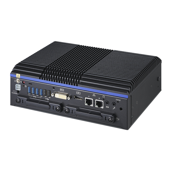
— — Product Nomenclature and Function BX-M4600 Series Reference Manual 1. Nomenclature of Product Components Component names of the product are shown in the figure below. (Heat sink shape will vary based on SKU) ◆ Front View ◆ Rear View... - Page 21 — — Product Nomenclature and Function BX-M4600 Series Reference Manual Item Name Function Front DC-IN DC power input connector POWER SW PC Power switch USB3.0 USB3.2 (Gen 2×1) port TYPE-A connector x 4 USB2.0 USB2.0 port TYPE-A connector x 2...
-
Page 22: Description Of Product Components
ON (Red) You can control the behavior of LED from the used application. *1 *1: API that controls Status LED is available. For more information, visit CONTEC’s website. 2. DC Power Input Connector: DC-IN To supply the power, always use the power supply listed below. -
Page 23: Power Sw
— — Product Nomenclature and Function BX-M4600 Series Reference Manual ◆ Rise time for power supply 3. Power SW The power switch is provided. The power of the product can be turned on or turned off with this switch. 4. LINE OUT Interface: LINE OUT The product is equipped with a connector for line output. -
Page 24: Serial-Ata: Sata 1, Sata 2
— — Product Nomenclature and Function BX-M4600 Series Reference Manual 6. Serial-ATA: SATA 1, SATA 2 The product has two ports of serial ATA 3.0 compliant controllers. Connector used on the product SATA connector Pin No. Signal name Pin No. -
Page 25: Dvi-I Interface
7. DVI-I Interface A DVI-I interface is provided. A CRT display (or a 15-pin D-SUB CRT when the included DVI–Analog RGB conversion adapter is used) or a flat-panel display from CONTEC can be connected. The connector name is DVI (DVI-I 29 pin). - Page 26 — — Product Nomenclature and Function BX-M4600 Series Reference Manual DVI-analog RGB conversion adapter Connector type DVI-I Analog RGB signals Pin No. Signal name Pin No. Signal name GREEN BLUE N.C. N.C. DDC DATA HSYNC VSYNC DDC CLK CAUTION If the OS is booted without connecting the display cable to the DVI interface, and then the ⚫...
-
Page 27: Display Port Interface
— — Product Nomenclature and Function BX-M4600 Series Reference Manual 8. Display Port Interface A display port interface is provided. As such, a display equipped with a Display Port can be connected. Connector used on the product Display Port 20 Pin... -
Page 28: Usb3.2 (Gen 2×1) Port
— — Product Nomenclature and Function BX-M4600 Series Reference Manual 9. USB3.2 (Gen 2×1) Port This product is equipped with 4 channels for USB 3.0 TYPE-A interface. USB3.2 Connector Pin No. Signal Name USB_VCC DATA- DATA+ USB_GND SSRX- SSRX+ USB_GND... -
Page 29: Gigabit-Ethernet
— — Product Nomenclature and Function BX-M4600 Series Reference Manual 11. Gigabit-Ethernet This product is equipped with 2 ports for gigabit. Network Type: 2500/1000 BASE-T/ 100 BASE-TX/ 10 BASE-T Transmission Speed : 2500M/1000M/ 100M/ 10M bps Max. network path length: 100m/ segment ®... -
Page 30: Serial Port Interface: Serial A, B, C, D
— — Product Nomenclature and Function BX-M4600 Series Reference Manual 12. Serial Port Interface: Serial A, B, C, D The product has 3 channels of RS-232C and 1 channel of RS-232C/422/485 compliant serial ports supporting up to a baud rate of 115,200bps with a 16-byte transmission-dedicated data buffer and a 16-byte reception-dedicated data buffer. - Page 31 — — Product Nomenclature and Function BX-M4600 Series Reference Manual Serial B, C, D port connector Connector used on the product 9-pin D-SUB (MALE) Pin No. Signal Name Description Direction Carrier detect Input Received data Input Transmitted data Output Data terminal ready...
-
Page 32: Dio Port
— — Product Nomenclature and Function BX-M4600 Series Reference Manual 13. DIO Port The product is equipped with an interface to which you can connect a remote switch and a GPIO device. GPIO is not isolated. Connector used on the product 9-pin D-SUB (Female) Pin No. - Page 33 — — Product Nomenclature and Function BX-M4600 Series Reference Manual ◆ Input equivalent circuit ◆ When selecting inputs (an example of connecting the product to a switch) When the switch is “ON”, the relevant bit indicates “0”. When the switch is “OFF”, the relevant bit indicates “1”.
-
Page 34: Jumper List
BX-M4600 Series Reference Manual 3 . Jumper List For users to customize BX-M4600 series features. In the following sections, short means covering a jumper cap over jumper pins; Open or N/C (not connected) means removing a jumper cap from jumper pins. Users can refer to below Top view picture and tables for jumper positions, functions, and signal description. -
Page 35: Hardware Setup
Hardware Setup This section describes how to install, connect, and set up the product. - 35 -... -
Page 36: Before Using The Product For The First Time
— — Hardware Setup BX-M4600 Series Reference Manual 1. Before Using the Product for the First Time Follow the next steps to set up this product: STEP1 By referring to the information in this section, install, connect and set up this product. -
Page 37: Hardware Setup
— — Hardware Setup BX-M4600 Series Reference Manual 2. Hardware Setup Before you start, be sure that the power is turned off. ⚫ Remove only those screws that are explained. Do not move any other screws. ⚫ You can equip the product with slot-in type 2.5-inch SATA storage. - Page 38 — — Hardware Setup BX-M4600 Series Reference Manual CAUTION When tightening the screws to fasten the HDD / SSD to the bracket or the HDD mounted bracket to the ⚫ product, do not use any tool such as an electric screwdriver, which vibrates the HDD / SSD. Not doing so will damage the HDD / SSD.
-
Page 39: Attaching The Attachment Fittings
— — Hardware Setup BX-M4600 Series Reference Manual 2. Attaching the Attachment Fittings CAUTION Screw holes may be damaged if screws are tightened with a torque greater than the specified ⚫ torque. The specified tightening torque is 5 - 6kgf・cm. -
Page 40: Fastening The Cable
— — Hardware Setup BX-M4600 Series Reference Manual 4. Fastening the Cable This produce comes with clamps for fixing cables. Fastening the USB cable. 1) he system unit has a hole for attaching cable clamp to USB removal prevention fitting. Using a cable clamp for a cable with lock-less connector, such as the USB cable, prevents the connector from being unplugged. - Page 41 — — Hardware Setup BX-M4600 Series Reference Manual 2) The photo below shows an example of using a cable clamp. Fix the cable with a clamp without applying stress to the connector. - 41 -...
-
Page 42: Installation Requirements
— — Hardware Setup BX-M4600 Series Reference Manual 5. Installation Requirements The product can be installed in any orientation (1) through (4). Increase the distance between the main unit and devices that generate heat or exhaust air, or take other measures to ensure the ambient temperature falls within the range specified in the installation environment requirements. - Page 43 — — Hardware Setup BX-M4600 Series Reference Manual Distances between this product and its vicinity - Vertical installation - Horizontal installation CAUTION Wall temperatures should be within the guaranteed operating temperature range of the ⚫ product. Adjust the air flow so as not to allow waste heat from the product to accumulate around the ⚫...
- Page 44 — — Hardware Setup BX-M4600 Series Reference Manual ◆ Ambient temperature In this product, the ambient temperature is decided from the multiple measurement points as shown below. When making use of the product, the air current should be adjusted to prevent that all the temperatures measured at the measurement points exceed the specified temperature.
-
Page 45: Bios Setup
BIOS Setup This section describes AMI’s Setup program built into the FLASH ROM BIOS. - 45 -... -
Page 46: Introduction
— — BIOS Setup BX-M4600 Series Reference Manual 1. Introduction This chapter discusses American Megatrends’ (AMI) Setup program built into the FLASH ROM BIOS. The Setup program allows users to modify the basic system configuration. This special information is then stored in FLASH ROM so that it retains the Setup information when the power is turned off. -
Page 47: Using Setup
— — BIOS Setup BX-M4600 Series Reference Manual 2. Using Setup In general, you use the arrow keys to highlight items, press <Enter> to select, use the PageUp and PageDown keys to change entries, press <F1> for help and press <Esc> to quit. The following table provides more detail about how to navigate in the Setup program using the keyboard. -
Page 48: Main Menu
— — BIOS Setup BX-M4600 Series Reference Manual 2. Main Menu When the setup program (Aptio Startup Utility) is started, the main menu will be displayed. Navigate through the various tabs by pressing the right and left arrow keys. - 48 -... -
Page 49: Setup Items
— — BIOS Setup BX-M4600 Series Reference Manual 1. Setup Items The selectable tabs are as follows. Main View the basic system structure and configure the language settings and the date and time settings. Advanced Specify the detailed functions that can be set on the system used. -
Page 50: Main
— — BIOS Setup BX-M4600 Series Reference Manual 3. Main View the basic system structure. The following items are displayed. Indication item of the main menu Item Indication Example Explanation Project Version R68000C 1.02 x64 Displays the BIOS version. Build Date and Time... -
Page 51: Advanced
— — BIOS Setup BX-M4600 Series Reference Manual 4. Advanced This section allows you to configure your CPU and other system devices for basic operation through the following sub-menus. CPU Configuration Configure the CPU settings. Power & Performance Power & Performance Options PCH-FW Configuration Configure the management engine technology parameters. - Page 52 — — BIOS Setup BX-M4600 Series Reference Manual Network Stack Configuration Network Stack settings. NVMe Configuration NVMe Device Options settings. Intel® Ethernet Controller I226-IT- ( LAN_A MAC ADDRS.) Configure 2.5Gigabit Ethernet device parameters.. Intel® Ethernet Controller I226-IT- ( LAN_B MAC ADDRS.) Configure 2.5Gigabit Ethernet device parameters..
-
Page 53: Cpu Configuration
— — BIOS Setup BX-M4600 Series Reference Manual 1. CPU Configuration Efficient-core Information (Efficiency core messages that will be displayed when the CPU SKU supports) Displays the E-core Information. Performance-core Information Displays the E-core Information. Item Options Description When enabled, a VMM can utilize the... - Page 54 — — BIOS Setup BX-M4600 Series Reference Manual Item Options Description Number of E-core to enable in each processor package. Active Efficient Cores Note: Number of cores and E-cores are looked at together. When both are { 0,0}, p-core will enable all cores...
- Page 55 — — BIOS Setup BX-M4600 Series Reference Manual Item Options Description Scroll LED is on and un-parked when LED is off - 55 -...
-
Page 56: Power & Performance
— — BIOS Setup BX-M4600 Series Reference Manual 2. Power & Performance Power & Performance Item Options Description Enabled Allows more then two frequency ranges to be Intel® Speedstep™ Disabled supported Enable / Disable Race to Halt feature. RTH dynamically... -
Page 57: Pch-Fw Configuration
— — BIOS Setup BX-M4600 Series Reference Manual 3. PCH-FW Configuration PCH-FW Configuration Item Options Description Enabled When disabled ME will be put into ME Temporarily ME State Disabled Disabled mode. Firmware update Configuration Enabled Me FW Image Re-Flash Enable / Disable Me FW Image Re-Flash function. -
Page 58: Trusted Computing
— — BIOS Setup BX-M4600 Series Reference Manual 4. Trusted Computing TRUSTED Configuration Item Options Description Enables or Disables BIOS support for security Device. Enable Security Device Support TCG EFI protocol. And INT1A interface will not be Disable available. Enabled... -
Page 59: Acpi Setting
— — BIOS Setup BX-M4600 Series Reference Manual 5. ACPI Setting ACPI Setting Item Options Description Enabled Enables or Disables BIOS ACPI Auto Enable ACPI Auto Configuration Disabled Configuration. Enables or Disables system ability to Hibernation (OS/S4 Sleep State).this Enabled... -
Page 60: Nct6126D Super Io Configuration
— — BIOS Setup BX-M4600 Series Reference Manual 6. NCT6126D Super IO Configuration Super IO Configuration default Item Options Description Serial Port 1 Configuration -IO=3F8h; IRQ=4; Refer to Serial Port 1 Configuration Serial Port 2 Configuration - IO=2F8h; IRQ=3; Refer to Serial Port 2 Configuration Serial Port 3 Configuration - IO=3E8h;... - Page 61 — — BIOS Setup BX-M4600 Series Reference Manual Item Options Description Enabled DIR1/2 Signal Inverts DIR1/2 Signal Inverts Disabled Serial Port 2 Configuration Item Options Description Enabled Configure the operation settings for serial Serial Port Disabled port 2 Auto IRQ=2F8h; IRQ=3;...
- Page 62 — — BIOS Setup BX-M4600 Series Reference Manual Item Options Description Configure the operation settings for Digital I/O (input/output). Digital I/O Pin 0 And, configure the operation settings for Digital I/O Pin 1 output-level (High/Low). Input Digital I/O Pin 2...
-
Page 63: Hardware Monitor
— — BIOS Setup BX-M4600 Series Reference Manual 7. Hardware Monitor View hardware monitor information such as the CPU temperature. Smart FAN Mode Configuration Item Options Description PWM Manual Mode System Smart FAN Mode Do not change this setting. Thermal Cruise Mode Fan less models will not display the smart fan option. -
Page 64: Usb Configuration
— — BIOS Setup BX-M4600 Series Reference Manual 8. USB Configuration USB Configuration Item Options Description Enables Legacy USB support. AURO option disable Enabled Legacy support if no USB device are connected. Legacy USB Support Disabled DISABLE option will keep USB device available Auto only for EFI applications. -
Page 65: Netware Stack Configuration
— — BIOS Setup BX-M4600 Series Reference Manual 9. Netware Stack Configuration Netware Stack configuration Item Options Description Enabled Netware Stack Enable /Disable UEFI network stack Disabled Enable option screen - 65 -... -
Page 66: Nvme Configurations
— — BIOS Setup BX-M4600 Series Reference Manual 10. NVMe Configurations (Picture showing the display example after NVMe SSD installation) - 66 -... -
Page 67: Intel®Ethernet Controller I226-It-(Lan_A: Mac Addrs)
— — BIOS Setup BX-M4600 Series Reference Manual 11. Intel®Ethernet Controller I226-IT- (LAN_A: MAC addrs) - 67 -... -
Page 68: Intel®Ethernet Controller I226-It-( Lan_B Mac Addrs)
— — BIOS Setup BX-M4600 Series Reference Manual 12. Intel®Ethernet Controller I226-IT- ( LAN_B MAC addrs) - 68 -... -
Page 69: Driver Health
— — BIOS Setup BX-M4600 Series Reference Manual 13. Driver Health - 69 -... -
Page 70: Chipset
— — BIOS Setup BX-M4600 Series Reference Manual 5. Chipset The following items are available System Agent (SA) Configuration Configure system agent (SA) settings. PCH-IO Configuration Configure the HD Audio subsystem. - 70 -... -
Page 71: System Agent (Sa) Configuration
— — BIOS Setup BX-M4600 Series Reference Manual 1. System Agent (SA) Configuration Memory Configuration Item Options Description Enable/Disable Realtime memory timings. when Enabled Realtime Memory Timing enabled, the system will allow performing Realtime Disabled memory timing changes after MRC_DONE Select DIMM timing profile.The below values start... - Page 72 — — BIOS Setup BX-M4600 Series Reference Manual Item Options Description Memory Test on Warm Enable or disable base memory test run on Enabled Disabled boot warm boot Maximum Memory Maximum Memory Frequency Selections in Auto 1067 ~12800 Frequency Memory Configuration (Please keep no change as default)
- Page 73 — — BIOS Setup BX-M4600 Series Reference Manual Item Options Description External Gfx Card Primary Display Configuration Auto Internal Graphics Keep OGFX enabled based n the setup options. Enabled Disabled GTT Size Select GTT size 128MB Select the Aperture Size...
- Page 74 — — BIOS Setup BX-M4600 Series Reference Manual Item Options Description PWM Normal Backlight Control Backlight Control setting PWM Inverted Select the Active LFP Configuration. No LVDS:VBIOS does not enable LVDS. Int-LVDS :V BIOS enables LVDS driver by Integrated eDP Port-A encoder.
- Page 75 — — BIOS Setup BX-M4600 Series Reference Manual PCI Express Configuration Item Options Description Disabled Fia Programming Load Fia Configuration if Enabled for each root port. Enabled Disabled Compliance Test Mode Enable when using Compliance Load Board Enabled Disabled CDR Relock...
-
Page 76: Pch-Io Configuration
— — BIOS Setup BX-M4600 Series Reference Manual 2. PCH-IO Configuration Configure how memory will be used when using the graphic function. Leave these settings as configured before shipment. SATA Configuration - 76 -... - Page 77 — — BIOS Setup BX-M4600 Series Reference Manual Item Options Description Enabled SATA Controller(s) Enable / Disable SATA Device Disabled SATA Mode Selection AHCI Determine how SATA controller(s) operate. Enabled SATA Test Mode Test Mode Enable/Disable(Loop Back) Disabled Enabled Aggressive LPM Support Enable PCH to aggressively enter link power state.
- Page 78 — — BIOS Setup BX-M4600 Series Reference Manual Item Options Description Direct Connect Flex Enable / disable SATA Port 4 DevSip. for DevSip to work, both hard drive and SATA port need to Enabled SATA Port 1 DevSip support DevSip function, otherwise an unexpected Disabled behavior might happen.
- Page 79 — — BIOS Setup BX-M4600 Series Reference Manual Item Options Description Enabled Onboard LAN A Controller Enabled / Disabled Onboard NIC Disabled Enabled Onboard LAN B Controller Enabled / Disabled Onboard NIC Disabled Enabled Enabled / Disabled LAN2 and PCIe Slot to wake the...
-
Page 80: Security
— — BIOS Setup BX-M4600 Series Reference Manual 6.Security Administrator Password Set the Administrator Password. Press Enter to display the following screen for entering the password. Administrator Password Create New Password **** Confirm New Password [ **** Enter a password at least 3 characters long twice. - Page 81 — — BIOS Setup BX-M4600 Series Reference Manual HDD Security Configuration ( T Secure Boo Item Options Description Secure Boot feature is Active if Secure Boot is Enabled Enabled, Platform Key(PK) is enrolled and system Secure Boot is user mode. The mode change requires platform...
-
Page 82: Boot
— — BIOS Setup BX-M4600 Series Reference Manual 7.Boot Configurate the settings boot devices and other devices CAUTION In the Boot Option #x device list, the same device may be displayed as follows. ⚫ USB Disk UEFI: USB Disk In such cases, if (1) is selected, a legacy boot is performed under the assumption the disk is MBR-formatted. -
Page 83: Save And Exit
— — BIOS Setup BX-M4600 Series Reference Manual 8.Save and Exit Load/ Save setup items and exit the setup menu. Save Changes and Exit Exit system setup after saving the changes. Discard Changes and Exit Exit system setup without saving any changes. -
Page 84: Software Raid Setup
— — BIOS Setup BX-M4600 Series Reference Manual Software RAID Setup This section describes software mirroring (RAID1) setup procedure. - 84 -... -
Page 85: Outline
1. Outline This section describes software mirroring (RAID1) setup. The CONTEC only supports mirroring. We do not support operation for other RAIDs. Be aware that functions not supported are outside the scope of the warranty. Software RAIDs are not hot-swappable. -
Page 86: Create Raid Volume (Raid1(Mirror))
Make sure to create RAID volume first, then install operating system. If you create a RAID volume after ⚫ installing OS, data will be erased, and it cannot start OS. The CONTEC only supports mirroring. If you intend to create RAID volume other than mirroring, we leave ⚫ it as user’s option. - Page 87 — — BIOS Setup BX-M4600 Series Reference Manual ◆ Create RAID volume. Go to Advanced> Intel(R) Rapid Storage Technology> Create RAID Volume. . Set RAID Level for <RAID1 (Mirror)>. In Select Disks, set <x> in [ ] for two of SATA disks that configure RAID.
- Page 88 — — BIOS Setup BX-M4600 Series Reference Manual Press [F4] key, select [Save & Exit Setup]. Please select [Yes] and press [ENTER] key. You have now finished creating RAID volume. After RAID volume has been created, the volume will be displayed in Advanced> Intel(R) Rapid Storage Technology>...
- Page 89 — — BIOS Setup BX-M4600 Series Reference Manual RAID Volume The state of RAID volume can be checked and deleted. Also, the state of SATA disk that configures RAID volume can be checked. RAID VOLUME INFO Item Options Description Delete...
-
Page 90: Delete Raid Volume (Raid1(Mirror))
— — BIOS Setup BX-M4600 Series Reference Manual 3. Delete RAID Volume (RAID1(Mirror)) Describe the procedure for deleting RAID volume. Follow the steps below on the BIOS setup screen. CAUTION Data may be lost if an existing RAID volume is deleted. Back up the data on a RAID volume before deleting it if the data is important. - Page 91 — — BIOS Setup BX-M4600 Series Reference Manual Press [F4] key, select [Save & Exit Setup]. Please select [Yes] and press [ENTER] key to save the setting. You have now finished deleting RAID volume. The volume will be deleted from Advanced> Intel(R) Rapid Storage Technology> RAID Volume. SATA disk that configured RAID volume will be displayed in "Non-RAID Physical Disks".
-
Page 92: Raid Setup When Replacing Sata Disk
— — BIOS Setup BX-M4600 Series Reference Manual 4. RAID setup when replacing SATA disk If you replace SATA disk while setting the software mirroring (RAID1), you need to rebuild the mirroring RAID drive. After replacing SATA disk, follow the steps below on the BIOS setup screen. - Page 93 — — BIOS Setup BX-M4600 Series Reference Manual Select the SATA disk to be Rebuild. Press [F4] key, select [Save & Exit Setup]. Please select [Yes] and press [ENTER] key to save the setting. You have now finished replacing SATA disk device.
-
Page 94: Appendix
Appendix This section lists the specifications and the physical dimensions of the product, and the details of model name. - 94 -... -
Page 95: System Reference
— — Appendix BX-M4600 Series Reference Manual 1. System Reference 1. Specifications Function Specifications Model Name BX-M4600G- BX-M4600G- BX-M4600G- BX-M4600G- G3200000 G5200000 G5300000 G73000000 Processor Intel® Core™ i3- Intel® Core™ i5- Intel® Core™ i5- Intel® Core™ i7- 13100TE 13500TE 13500TE... - Page 96 — — Appendix BX-M4600 Series Reference Manual Mechanical Thermal Design Fan-less Mounting Wall mount, Desktop, VESA mount Dimension (WxDxH) 235 x 185 x 74 mm (No protrusions) Weight 3.0 kg Material Top Cover: Aluminum Alloy Bezel and Chassis: Steel Environmental Core™...
-
Page 97: Power Management Features
— — Appendix BX-M4600 Series Reference Manual 2. Power Management Features - Support both ACPI (Advanced Configuration and Power Interface). - ACPI v2.0 compliant - Hardware automatic wake-up 3. Power Requirements Your system requires a clean, steady power source for reliable performance of the high frequency CPU on the product, the quality of the power supply is even more important. -
Page 98: Physical Dimensions
— — Appendix BX-M4600 Series Reference Manual 2. Physical Dimensions All Dimensions shown in mm (millimeters.) * The length (L) from the tip of M4 boss to the M4 screw tip should be 5mm or less. If not doing so, it may be exactly fixed. -
Page 99: Maintenance
— — Appendix BX-M4600 Series Reference Manual 3. Maintenance 1. Battery Battery Specification This product uses the following battery. - Type: Lithium primary battery - Model: BR-2032/BN - Maker: Panasonic - Nominal voltage: 3V - Nominal capacity: 190 mAh - Lithium content: 1g or less Removing the battery Remove the battery according to the following figure. -
Page 100: Post Codes
— — Appendix BX-M4600 Series Reference Manual 4.Post Codes Description POST (hex) < Security (SEC) phase > Power ON. The detection of the reset kind (Hard/Soft) Initialize the microcode load previous AP Initialize the microcode load previous North Bridge Initialize the microcode load previous South Bridge... - Page 101 — — Appendix BX-M4600 Series Reference Manual POST Description South Bridge runtime services installation (hex) CPU DXE installation start 64h - 67h CPU DXE installation start (Specific CPU module) PCI host bridge installation North Bridge DXE initialization starts North Bridge DXE SMM initialization starts...
- Page 102 — — Appendix BX-M4600 Series Reference Manual Description POST Legacy boot event (hex) Boot Service event ends Virtual address maps run-time settings begin. Virtual address maps of runtime configuration exit Legacy option ROM initialization System reset USB hot plug PCI bus hot plug...
-
Page 103: Serial I/O Address And Register Function
— — Appendix BX-M4600 Series Reference Manual 5.Serial I/O Address and Register Function The following table lists the I/O addresses in case of SERIAL A. I/O Port Addresses I/O address DLAB Read/Write Register 03F8H Transmitter holding register Receiver buffer register... - Page 104 — — Appendix BX-M4600 Series Reference Manual I/O address Description IER: Interrupt Enable Register [DLAB=0] 03F9H IIR: Interrupt Identification Register 03FAH LCR: Line Control Register 03FBH - 104 -...
- Page 105 — — Appendix BX-M4600 Series Reference Manual Description I/O address MCR: Modem Control Register 03FCH LSR: Line Status Register 03FDH MSR: Modem Status Register 03FEH SCR: Scratchpad Register This is an 8-bit, readable/writable register which is available to the 03FFH user to allow data to be saved temporarily.
- Page 106 — — Appendix BX-M4600 Series Reference Manual Baud Rate Settings A baud rate is set by software by dividing the clock input (1.8432MHz). The baud rate in terms of hardware can be set to a maximum of 115,200 bps for SERIAL Port. The baud rates available in practice depend on the operating environment (cable, software, etc.).
-
Page 107: Watch-Dog-Timer
— — Appendix BX-M4600 Series Reference Manual 6.Watch-Dog-Timer The watchdog timer serves as a safeguard against possible system lock-up in your industrial computer system. In most industrial environments, there are heavy equipment, generators, high- voltage power lines, or power drops that have adverse effects on your computer system. For instance, when a power drop occurs, it could cause the CPU to come to a halt state or enter into an infinite loop, resulting in a system lock-up. - Page 108 — — Appendix BX-M4600 Series Reference Manual Example programming The following example is written in Intel8086 assembly language. ;=============== ;<WDT Initial> ;=============== ;------------------------------------------- ;Enter the extended function mode ;------------------------------------------- MOV DX,2EH MOV AL,87H OUT DX,AL OUT DX,AL ;---------------------------------------------- ;Select logical device WDT(number 8) ;----------------------------------------------...
- Page 109 — — Appendix BX-M4600 Series Reference Manual MOV AL,00H OUT DX,AL ;------------------------------------------ ;Exit the extended function mode ;------------------------------------------ MOV DX,2EH MOV AL,AAH OUT DX,AL ;=============================== ;<WDT START: counter set and a start> ;=============================== ;--------------------------------------------- ;Enter the extended function mode ;---------------------------------------------...
- Page 110 — — Appendix BX-M4600 Series Reference Manual ;---------------------------------------------------------------------------------- OUT DX,AL ;--------------------------------------- ;Exit the extended function mode ;--------------------------------------- MOV DX,2EH MOV AL,AAH OUT DX,AL ;============== ;<WDT STOP> ;============== ;----------------------------------------- ;Enter the extended function mode ;----------------------------------------- MOV DX,2EH MOV AL,87H OUT DX,AL OUT DX,AL ;-----------------------------------...
- Page 111 — — Appendix BX-M4600 Series Reference Manual ;----------------------------------- OUT DX,AL ;----------------------------------- ;Exit the extended function mode ;----------------------------------- MOV DX,2EH MOV AL,AAH OUT DX,AL CAUTION The timer’s intervals have a tolerance of ± 2 seconds. ⚫ - 111 -...
-
Page 112: Gpio Sample Code
— — Appendix BX-M4600 Series Reference Manual 7.GPIO Sample Code Sample Code EX. Sample Code Using GP4X #include <conio.h> #include <stdio.h> #include <io.h> void main(void) unsigned char byte_cr1c; outportb(0x2e, 0x87); // enter Super I/O configuration mode outportb(0x2e, 0x87); outportb(0x2e, 0x07); // locate logical device 7 outportb(0x2f, 0x07);... -
Page 113: List Of Optional Products
List of Optional Products This section lists optional items that can be used along with the product. - 113 -... -
Page 114: Optional Product
*VESA Module *HDD 2.5” SATA HDD Max to 1TB *SSD 2.5” SATA SSD Max to 64GB Visit the CONTEC website for the latest optional products. *Option will be available. Please contact your Field Sales Rep https://www.contec.com/ Download - 114 -... -
Page 115: Customer Support And Inquiry
Customer Support and Inquiry CONTEC provides the following support services for you to use CONTEC products more efficiently and comfortably. - 115 -... -
Page 116: Services
— — Customer Support and Inquiry BX-M4600 Series Reference Manual 1. Services CONTEC offers the useful information including product manuals that can be downloaded through the CONTEC website. Download https://www.contec.com/download/ You can download updated driver software, firmware, and differential manuals in several languages. Membership registration (myCONTEC) is required to use the services. - Page 117 —— BX-M4600 Series Reference Manual Revision History MONTH YEAR Summary of Changes March 2024 The First Edition - 117 -...
- Page 118 3-9-31, Himesato, Nishiyodogawa-ku, Osaka 555-0025, Japan https://www.contec.com/ No part of this document may be copied or reproduced in any form by any means without prior written consent of CONTEC CO., LTD. BX-M4600 Series Reference Manual NA09978 (LXDJ071) [03152024] March 2024 Edition...
Need help?
Do you have a question about the BX-M4600 Series and is the answer not in the manual?
Questions and answers