
Related Manuals for Contec IPC-BX/600(PCW)


Summary of Contents for Contec IPC-BX/600(PCW)
- Page 1 IPC Series BOX-PC IPC-BX/600(PCW), IPC-BX/600(PCW)C, IPC-BX/600(PCW)CP, IPC-BX/600(PCW)C4P User's Manual CONTEC CO.,LTD.
-
Page 2: Trademarks
Copyright 2001 CONTEC CO., LTD. ALL RIGHTS RESERVED No part of this document may be copied or reproduced in any form by any means without prior written consent of CONTEC CO., LTD. CONTEC CO., LTD. makes no commitment to update or keep current the information contained in this document. -
Page 3: Table Of Contents
Table of Contents Copyright ................i Trademarks................ i 1.Introduction ..............1 Features ................ 1 Compatible Operating Systems........2 Limited One-Year Warranty ........2 How to Obtain Service ..........2 Liability ................ 2 Handling Precautions ..........3 About the Manual ............5 2.Overview ............... - Page 4 Cache Memory Window..........37 I/O Device Configuration Window ......38 Security Window............41 Power Window ............42 Boot Window ............... 43 Exit Window..............44 5.Each Component Function ........... 47 Component Identification .......... 47 Keyboard Interface ............. 50 Mouse Interface ............50 Floppy Disk Interface..........
- Page 5 User’s Manual...
-
Page 6: Introduction
Recent years have seen an increasing number of users who embrace FA and LA utilizing personal computers. In response to this trend, CONTEC has developed and marketed FA computers (the IPC series) and a variety of interface boards. -
Page 7: Compatible Operating Systems
Please obtain a Return Merchandise Authorization Number (RMA) from the CONTEC group office where you purchased before returning any product. * No product will be accepted by CONTEC group without the RMA number. Liability The obligation of the warrantor is solely to repair or replace the product. -
Page 8: Handling Precautions
- Before installing or uninstalling an expansion board (the CP model) or connecting or disconnecting a connector, be sure to unplug the power cable from the wall outlet. - CONTEC reserves the right to refuse to service a product modified by the user. User’s Manual... - Page 9 CONTEC Information Center. - Use an AC cable that is compatible with both the rated supply voltage and the receptacle. (The cable provided with the product is for 125VAC.)
-
Page 10: About The Manual
1. Introduction About the Manual This manual consists of the following chapters: Chapter 1 Introduction Chapter 2 Overview Chapter 3 Hardware Setup Chapter 4 BIOS Setup Chapter 5 Each Component Function Chapter 6 Appendix Chapter 7 List of Options User’s Manual... - Page 11 1. Introduction User’s Manual...
-
Page 12: Overview
Approx. 4.2 kg Approx. 5.0 kg *1 Used with a display installed with a touch panel of Contec panel-linkage specifications. *2 Not all functions can be used simultaneously due to a limit on the number of interrupt resources. User’s Manual... - Page 13 2. Overview Table 2.2. Installation Environment Requirements Parameter Requirement description Power supply specifications Allowable instantaneous Less than 20ms power outage One minute each for 3.0 kVAC (input-output), 2.0 kVAC (input-FG), Dielectric strength and 0.5 kVAC (output-FG) Insulation resistance 50M Ω (DC500V) Ambient specifications 0 to 50ºC(SDD in use) Operating temperature...
-
Page 14: System Configuration
2. Overview System Configuration 2.5inch hard (silicon) disk drive Main memory 144pin SO-DIMM Dedicated LCD IPC-BX/M600(PCW)CP Built-in IPC-DT/L40S(PC)T IPC-DT/H40X(PC)T Dedicated Terminal block RS-485 General-purpose I/O (3) Dedicated LCD cables IPC-PL2020-020 (2m) IPC-PSD-20 IPC-PL2020-050 (5m) RS-232C Mouse Option CD-ROM CRTdisplay Keyboard Dedicated FD Drive PC-FDD25BH PCMCIA card slot (C, CP and C4P models) -
Page 15: External Dimensions
2. Overview External Dimensions IPC-BX/M600(PCW) 4- Φ 5 [mm] Figure 2.2. IPC-BX/M600(PCW) Note! The panel link interface and PC card connector are not installed on the IPC-BX/M600(PCW). User’s Manual... - Page 16 2. Overview IPC-BX/M600(PCW)C 4- Φ 5 [mm] Figure 2.3. External Dimensions of the IPC-BX/M600(PCW)C User’s Manual...
- Page 17 2. Overview IPC-BX/M600(PCW)CP 4- Φ 5 [mm] Figure 2.4. External Dimensions of the IPC-BX/M600(PCW)CP User’s Manual...
- Page 18 2. Overview IPC-BX/M600(PCW)C4P 4-Φ5 [mm] Figure 2.5. External Dimensions of the IPC-BX/M600(PCW)C4P User’s Manual...
- Page 19 2. Overview User’s Manual...
-
Page 20: Hardware Setup
3. Hardware Setup 3. Hardware Setup Before Using the BOX-PC for the First Time Follow the next steps to set up the BOX-PC: STEP1 Install the hard disk and expansion main memory (DIMM) and set jumper switches. By referring to the information in this chapter, set the BOX-PC. -
Page 21: Hardware Setup
3. Hardware Setup Hardware Setup Removing the Top Cover and HDD Bracket - Before you start, be sure that the power is turned off. - Remove only those screws that are explained. Do not move any other screw. (1) Remove the top cover. Figure 3.1. - Page 22 3. Hardware Setup (2) Remove the hard disk bracket. Figure 3.2. Removing the HDD Bracket User’s Manual...
-
Page 23: Locations And Settings Of Internal Connectors And Jumpers
3. Hardware Setup Locations and Settings of Internal Connectors and Jumpers When you remove the top cover and hard disk bracket, the connectors, jumpers, and switches are laid out as shown in the figure below: CN15 1 2 3 1 2 3 * The position of the jumpers mounted changes with kinds (A, B) of substrate. - Page 24 3. Hardware Setup Table 3.1. Jumper List Reference Function Factory setting Remarks page - Selects BUS clock scale. 1-2 shorted Settings other than 1-2 are not allowed. - Clear CMOS. 1-2 shorted Short 2-3 to clear CMOS. - Sets RS-485 termination. 2-3 shorted - Sets destination where BIOS 1, 3, 4, and 8 OFF...
-
Page 25: Installing The Hard Disk
3. Hardware Setup Installing the Hard Disk (1) Connect the provided HDD cable to the hard disk (silicon disk). Note! Connect the HDD cable in alignment with pins from the left end of the connector on the HDD side. Four master/slave setting pins are left unconnected on the right side. -
Page 26: Installing The Main Memory (Dimm)
- Optional memories * : 64MB : PC-MSD64-144H 128MB : PC-MSD128-144H * Operation is not guaranteed if memory parts other than CONTEC option products are used. Main Memory (DIMM) Installation Procedure Follow the next steps to fit the memory into the DIMM socket:... - Page 27 3. Hardware Setup (1) Insert the DIMM into its socket with the notch positioned on the right side. (See the note.) DIMM Note: As shown in the Figure, insert socket the DIMM in angle. 30°~45° Notch Inserting as indicated with "x" may damage socket pins.
-
Page 28: Fastening The Power Cable
3. Hardware Setup Fastening the Power Cable Removing the Screw on the Metal Brace to Keep the AC Cord in Place In order to install the metal brace, temporarily remove the machine screw on the front left end. Remove this screw. Figure 3.7. -
Page 29: Installation Requirements
3. Hardware Setup Installation Requirements The BOX-PC can be installed in any orientation (1) through (5). Avoid orientation (6) since it might not adequately dissipate heat. Similarly, to maintain the ambient temperature within the range specified in the specifications, ensure a clearance between the unit and surrounding equipment of at least 100mm for the top and rear and 50mm for the bottom and sides. - Page 30 3. Hardware Setup Distances between the BOX-PC and Its Vicinity 50mm or more (side) 50mm or more (side) 100mm or more (above) 50mm or more (back) Connectors Figure 3.11. Distances between the BOX-PC and Its Vicinity User’s Manual...
- Page 31 3. Hardware Setup User’s Manual...
-
Page 32: Bios Setup
SETUP" if the system is normal. Press the <F2> key on the keyboard. Phoenix BIOS 4.0 Release 6.0 Copyright 1985-2000 Phoenix Technologies Ltd. All Rights Reserved Copyright 2000, CONTEC Co., Ltd. BX/M600(PCW), Px/x600(PCW) sereies BIOS ver.1.00. CPU = Intel(R) Mobile Celeron(TM) processer 400MHz... -
Page 33: Keystrokes
4. BIOS Setup Keystrokes The following is a list of major key functions you can use during BIOS setup: Table 4.1. Key Function List Key to press Function → , ← Moves the main menu. ↑ , ↓ Moves between items to be set. <Tab>... -
Page 34: Main Menu
4. BIOS Setup Main Menu PhoenixBIOS Setup Utility Main Embedded Advanced Security Power Boot Exit Item Specific Help System Time: [09:21:27] System Date: [01/01/1993] Legacy Diskette A: [1.44/1.25 MB "] Legacy Diskette B: [Disabled] Floppy Drive Swap: [Disabled] 3 MODE floppy: [Disabled] Primary Master [4312MB]... -
Page 35: Ide Adapter Window
4. BIOS Setup Primary Master : Set the type of HDD to be used as the first drive. If you are not using the HDD, set to "None." Select "Auto" setup to make setting easier. Primary Slave : Connection not allowed. Set to "None."... -
Page 36: Embedded Window
4. BIOS Setup Embedded Window PhoenixBIOS Setup Utility Main Embedded Advanced Security Power Boot Exit Item Specific Help Keyboard Error Disp.: [Disabled] RTC check: [Enabled] Restrain error display Memory Safemode: [Enabled] of no keyboard. System Clock(CPU/PCI MHz): [100.3/33.43] Spread Spectrum Modulation: [Enabled] CRT/FPD: [AUTO Select]... - Page 37 4. BIOS Setup CRT/FPD : Specify the display type. Choose from "CRT Only," "AUTO Select," "SW Select," "VGA TFT," "SVGA TFT," and "XGA TFT." When you are using only a CRT, select "CRT." For others, set to "AUTO Select." AUTO Select: It automatically recognizes the type of FPD with COM-port signals on the FPD signal when PC startups.
- Page 38 4. BIOS Setup PO2/WDT(12) signal to PO2 (general- purpose output). Enable: Sets the RAS connector's PO2/WDT(12) signal to Alarm Out. Alarm out status at BIOS startup should be set with the submenu. PCIC Irq Mode : Set to "Continous". Push switch function : Set to "Reset".
-
Page 39: Advanced Window
4. BIOS Setup Advanced Window PhoenixBIOS Setup Utility Main Embedded Advanced Security Power Boot Exit Item Specific Help Installed O/S: [Other] Enabled ACPI: [No] Select the operating Reset Configuration Data: [No] system installed PCI Configuration on your system which Cache Memory you will use most Legacy USB Support: [Disabled]... - Page 40 4. BIOS Setup PCMCIA ATA DISK * : Specify when the ATA card needs to be booted. Ensure that the setting does not collide with a local IDE controller. ATA card boot cannot be used in Windows, for example. * As to the local bus IDE adapter and the PCMCIA ATA DISK, a combined total of two units can be used at maximum.
-
Page 41: Pci Configuration Window
4. BIOS Setup PCI Configuration Window PhoenixBIOS Setup Utility Main Embedded Advanced Security Power Boot Exit PCI Configuration Item Specific Help PCI/PNP ISA UMB Region Exclusion Reserve specific upper PCI/PNP ISA IRQ Resource Exclusion memory blocks for use PCI/PNP ISA DMA Resource Exclusion by legacy ISA devices ↓... -
Page 42: Cache Memory Window
4. BIOS Setup PCI/PNP ISA DMA Resource Exclusion : When using a DMA board for ISA, set the DMA channel that board will be using to Reserved. * Do not set all of these resources to “Reserved”, or BIOS Setup will be unable to be invoked. -
Page 43: I/O Device Configuration Window
4. BIOS Setup I/O Device Configuration Window PhoenixBIOS Setup Utility Main Embedded Advanced Security Power Boot Exit I/O Device Configulation Item Specific Help Serial port A: [Enabled] Configure serial port A Base I/O address: [3F8] using options: Interrupt: [IRQ 4] Serial port B: [Enabled] [Disabled]... - Page 44 4. BIOS Setup Parallel port : This setting is for PRINTER on the equipment connector plane. When the port is set to "Enable," it defaults to the following: Mode [ECP] Base I/O address [378] Interrupt [IRQ7] DMA channel [DMA3] Items to be set Enable: Manually set the base I/O address and IRQ.
- Page 45 4. BIOS Setup Note! If the following message appears on booting when serial port D or the parallel port are set to “Enable”, this indicates a resource (IRQ) conflict or similar BIOS problem. Error 0615: Com D configuration changed In this case, enter the setup menu again and change the IRQ from “Reserved”...
-
Page 46: Security Window
4. BIOS Setup Security Window PhoenixBIOS Setup Utility Main Embedded Advanced Security Power Boot Exit Item Specific Help Set User Password [Enter] Set Supervisor Password [Enter] Supervisor Password controls access to the Supervisor Password Is: Clear setup utility. User Password Is: Clear Password on boot: [Disabled]... -
Page 47: Power Window
4. BIOS Setup Power Window PhoenixBIOS Setup Utility Main Embedded Advanced Security Power Boot Exit Item Specific Help Power Savings: [Disabled] Maximum Power Savings Standby Timeout: [Off] conserves the greatest Auto Suspend Timeout: [Off] amount of system power. Maximum Performance IDE Drive 0 Monitoring: [Disabled] conserves power but... -
Page 48: Boot Window
4. BIOS Setup Boot Window PhoenixBIOS Setup Utility Main Embedded Advanced Security Power Boot Exit *Removable Devices Item Specific Help *Hard Drive Bootable Add-in Cards Keys used to view or WDC AC14300R-(PM) configure devices ATAPI CD-ROM Drive <Enter> expands or Network Boot collapses devices with a - or... -
Page 49: Exit Window
4. BIOS Setup Exit Window PhoenixBIOS Setup Utility Main Embedded Advanced Security Power Boot Exit Exit Saving Changes Item Specific Help Exit Discarding Charges Load Setup Defaults Exit System Setup and Discard Changes save your changes to Saves Changes CMOS. ↓... - Page 50 4. BIOS Setup Save Changes : Saves values that have been modified on the setup screen in CMOS (EEPROM *1). *1 S1's bit 2 allows you to specify the location where setup details will be saved and loaded. Normally, set to ON (use CMOS). ON: Uses the CMOS as the location to save and load setup details.
- Page 51 4. BIOS Setup User’s Manual...
-
Page 52: Each Component Function
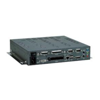
5. Each Component Function 5. Each Component Function Component Identification IPC-BX/M600(PCW) LCD and PCMCIA connectors not mounted. Top cover SERIAL2 HDD LED POWER SW MOUSE Keyboard AC inlet POWER LED SERIAL1 PRINTER UTP(Ethernet) RESET IPC-BX/M600(PCW)C Top cover HDD LED SERIAL2 PCMCIA POWER SW MOUSE... - Page 53 5. Each Component Function IPC-BX/M600(PCW)C4P Expansion slot(PCI/ISA) x 2 and PCI x 2 Top cover PCMCIA slots 1 and 2 HDD LED SERIAL2 POWER SW MOUSE Keyboard AC inlet POWER LED SERIAL1 PRINTER UTP(Ethernet) RESET Side view IPC-BX/M600(PCW), IPC-BX/M600(PCW)CP IPC-BX/M600(PCW)C IPC-BX/M600(PCW)C4P Secondary IDE Connector Figure 5.1.
- Page 54 5. Each Component Function Table 5.1. Component Functions Component Function Keyboard connector (MINI-DIN, 6pin) MOUSE PS/2 mouse connector (MINI-DIN, 6pin) Floppy disk drive connector (26pin, half-pitch connector) SERIAL1 Serial port 1 connector (9pin, male D-SUB) SERIAL2 Serial port 2 connector (9pin, male D-SUB) CRT connector (15pin, female HD-SUB) PCMCIA PCMCIA card slot <C, CP and C4P models>...
-
Page 55: Keyboard Interface
5. Each Component Function Keyboard Interface The BOX-PC is equipped with a keyboard connector named KB (MINI-DIN 6P). Table 5.2. Keyboard Connector Connector type Equivalent to the MD-DS12300-14S-14 (JST) Signal Pin No. Pin No. Signal +KBD DATA +KBD CLK N.C. N.C. -
Page 56: Floppy Disk Interface
5. Each Component Function Floppy Disk Interface The BOX-PC is equipped with a FD controller to allow one FD drive to be connected to the FD connector named FD on the front end. Use the FD drive that is available as a dedicated option. Table 5.4. - Page 57 5. Each Component Function Compatible Connector on the Cable Side Plug connector : AMP, P/N 1756774-4 (AWG#28 for pressure welding) Shield case kit : AMP, P/N 1756774-4 Plug connector : 3M, P/N 10126-6000EL (AWG#28 for pressure welding) Shell : 3M, P/N 10326-3210-000 Plug connector : 3M, P/N 10126-3000VE (AWG#24-#30 provided with solder) Shell system...
-
Page 58: Serial Port Interface
5. Each Component Function Serial Port Interface RS-232C Ports (Serial ports A and B) The BOX-PC is equipped with two RS-232C-compliant serial port connectors (SERIAL1: Serial port A and SERIAL2: Serial port B). Each port can be set independently to COM1-COM4 or "not in use" by BIOS setup (the identical COM number cannot be specified). - Page 59 5. Each Component Function RS-422/485 Port (Serial port D) The BOX-PC is equipped with a serial port for one channel inside the RAS connector. BIOS setup (see Chapter 4) allows I/O addresses, interrupts and "not in use" to be set. (The port cannot be set to the same I/O address or interrupt as of another device.) Table 5.7.
- Page 60 5. Each Component Function Terminal Resistor when RS-485 is in Use Set with JP4 inside the top cover. The factory setting is " terminal resistor not available." 2 and 3 shorted 1 and 2 shorted Receiver terminal Receiver terminal resistor not available resistor available Figure 5.2.
- Page 61 5. Each Component Function I/O Addresses and Instructions The I/O addresses and instructions of COM1 are shown next. Table 5.9. I/O Addresses Register I/O address DLAB Read/Write Transmitter holding register 03F8H Receive buffer register Divisor latch register Divisor latch register 03F9H Interrupt enable register 03FAH...
- Page 62 5. Each Component Function Table 5.10. Function of Each Register < 1 / 4 > I/O address Description 03F8H THR: Transmitter Holding Register [DLAB=0] bit7 bit0 Register dedicated to write transmitted data to 03F8H RBR: Reciever Buffer Register [DLAB=O] bit7 bit0 Register dedicated to read received data from 03F8H...
- Page 63 5. Each Component Function Table 5.10. Function of Each Register < 2 / 4 > I/O address Description 03FAH IIR : Interrupt Identification Register Interrupt details 1: Do not generate interrupts 0: Generate interrupts bit2 bit1 bit0 Priority Description Interrupts are not generated. Generated by overrun, parity, framing error or break 1 (high) interrupt.
- Page 64 5. Each Component Function Table 5.10. Function of Each Register < 3 / 4 > I/O address Description 03FCH MCR: Modem Control Register Loop IRQ RTS DTR 0 : Inactive [HIGH] 1 : Active [LOW] RTS 0 : Inactive [HIGH] 1 : Active [LOW] Interrupt control bit...
- Page 65 5. Each Component Function Table 5.10. Function of Each Register < 4 / 4 > I/O address Description 03FEH MSR : Modem Status Register DSR CTS DDCD TERI DDSR DCTS Delta CTS Delta DSR Since these statuses are Trailing edge RI not used with Delta data carrier detect RS-485, data...
-
Page 66: Crt Interface
VSYNC N.C. Display Driver The display driver compatible with each OS is downloadable from the CONTEC home page or can be purchased separately as an option. Set of optional driver software and utility software : IPC-SLIB-01 (provided on a CD-ROM) (Windows 98 Second Edition, Windows NT 4.0, Windows 2000... -
Page 67: Pcmcia Slots (C, Cp And C4P Models)
5. Each Component Function PCMCIA Slots (C, CP and C4P Models) The BOX-PC is equipped with PCMCIA-compliant card slots [TYPE II x 2 (TYPE III x 1) size]. Slot 1 Slot 2 Figure 5.3. Slot Numbers and Locations Note! A type III card should be inserted into slot 2. Attaching the Metal Brace to Keep the Card in Place Insert the front end. -
Page 68: Printer Port Interface
5. Each Component Function Printer Port Interface The BOX-PC is equipped with one printer port interface. BIOS setup (see Chapter 4) allows LPT1-3 and "not in use" to be set. The connector is named PRINTER. Table 5.15. Printer Ports and I/O Addresses LPT I/O address Interrupt 3BCh-3BFh... -
Page 69: Ras Functions
5. Each Component Function RAS Functions As RAS functions, the BOX-PC is equipped with watchdog timer, remote reset, and general-purpose I/O functions. Each I/O can be achieved with the RAS connector. Table 5.17. RAS Connector Connector type 15pin D-SUB(FEMALE) (DALC-J15SAF-20L9) JAE Pin No. -
Page 70: Watchdog Timer
5. Each Component Function Watchdog Timer The watchdog timer is started by output of A5 to I/O port address 4002h. A second output of A5 to the same port within the specified expiration time once again triggers the watchdog timer. If a time-out occurs, a reset or an interrupt is generated according to the 4004h port setting or an alarm is output according to the 4004h port setting. - Page 71 5. Each Component Function How to Use the Watchdog Timer BIOS setting Power ON Set counter Output data to ports 0070h and 0071h to set the clock counter clock. Output data to ports 4001h and 4004h to set event Set event output mode and external alarm.
- Page 72 5. Each Component Function Out 0070h 0Bh : Set the counter clock index register to register B. In 0071h : Read register B to view rsv bit status. Out 0071h 0Ah : Set counter clock output to Enable. : (Do not change the rsv bit.) Out 4004h 02h : Set the event at the time of WDT expiration to IRQ5.
- Page 73 5. Each Component Function * 0071h: Counter clock setting 2 (clock control register) Set clock frequency in register A and control output with register B. R/W (default: 00100110b) Figure 5.7. Register A: Counter Clock Frequency Setting Table 5.19. Counter Clock Frequency Settings RS3 RS2 RS1 RS0 Counter clock Unit...
- Page 74 5. Each Component Function * 4001h (bit4-6): Alarm out output control WD_S1 WD_S0 PO2_M RESET PIM2 PIM1 PIM0 R/W (Default: X0XX0000b) Figure 5.9. Alarm Out Output Control Port (4001h) PO2_M PO2/WDT pin output setting Set the RAS connector's PO2/WDT(12) signal to PO2 (general-purpose output).
- Page 75 5. Each Component Function * 4003h: WDT counter Figure 5.11. WDT Counter Port (4003h) Writes watchdog timer count data. Write watchdog timer counter expiration time data. The watchdog timer counter clock can be set to 13 levels within a range of 244.14 µsec through 1sec.
- Page 76 5. Each Component Function Table 5.22. RESET: Reset Output Modes RESET RESET output at occurrence of WDT errors Inhibits RESET output when time expires on the WDT. Allows RESET output when time expires on the WDT. Note! When time expires on WDT, the alarm-out is output irrelevant to the settings of the port for controlling event output.
-
Page 77: General-Purpose I/O And Remote Reset
5. Each Component Function General-purpose I/O and Remote Reset The BOX-PC is equipped with three general-purpose insulated signals each for input and output. The input signals can also be used for interrupt input or remote reset input. Specifications [ Input ] - Input specifications : Current-driven input by photocoupler insulation. - Page 78 5. Each Component Function I/O Addresses and Instructions * 4000h: General-purpose I/O PIO2 PIO1 PIO0 Figure 5.15. General-purpose Input Port (4000h) Read data from PI0, PI1 and PI2. Set data to be output to PO0, PO1 and PO2. * 4001h (bit0-3): PI2/IRQ(14) event input control WD_S1 WD_S0 PO2_M...
- Page 79 5. Each Component Function * 4006h: Index address setting Figure 5.17. Index Address Setting Port (4006h) Index address setting When specifying the RS-485 setting with port 4007h, output 00h to this port before you specify the setting. (* Index addresses other than 00h are used by the system.
- Page 80 5. Each Component Function 0 : Controlled by RTS TE_SEL 1 : Controlled by TE_GATE 0 : Transmission prohibited 1 : Transmission permitted RX-(11) 0 : Transmission permitted TE_GATE RX+ (3) 1 : Transmission prohibited TX-(10) TX+ (2) 0 : Receiving permitted RE_GATE 47k Ω...
-
Page 81: Reset Switch
5. Each Component Function (External circuit) Lard 510 Ω (PO 0~2) External power PC817 (Max. 30VDC) 2N3904 4.7k Ω (NCOM) RAS connector Figure 5.22. Output Circuit S1's bit 2 selects whether to use CMOS or EEPROM for BIOS setup details. For more information, see Chapter 4, "BIOS Setup." S1's bits 5-8 are the LCD setting switch. -
Page 82: Usb Ports
5. Each Component Function USB Ports The BOX-PC is equipped with two USB interface channels. Table 5.25. USB Connector Signal Signal Pin No. Pin No. USB0 Vcc USB1 Vcc USB0 -Data USB1 -Data USB0 +Data USB1 +Data USB0 GND USB1 GND User’s Manual... -
Page 83: Ethernet
5. Each Component Function Ethernet The BOX-PC is equipped with Fast-Ethernet. - Network type : 100BASE-TX/10BASE-T - Transmission speed* : 100M/10M bps - Max. network path length: 100m/segment - Controller : 82559(INTEL) * Operation at 100Mbps requires a category 5 cable. Table 5.26. -
Page 84: Liquid Crystal Display (Lcd) Interface
Liquid Crystal Display (LCD) Interface The BOX-PC is equipped with an LCD connector to allow an LCD manufactured by CONTEC to be connected. The table below lists the LCDs that can be connected. Set S1-5 through S1-8 according to the display in use. Note that in order to connect an LCD, you need a connecting cable. - Page 85 5. Each Component Function Table 5.28. LCD Connection List Display Model Display SW1 settings S1-5 : ON 12.1inch TFT with IPC-DT/L40S(PC)T SVGA S1-6 : ON a panel-mounting (800 x 600) S1-7 : ON touch panel S1-8 : OFF S1-5 : OFF 15inch TFT with IPC-DT/H40X(PC)T S1-6 : ON...
-
Page 86: Ide Interface
5. Each Component Function IDE Interface Connector for the Internal Drive (Primary IDE Connector) The BOX-PC is equipped with an E-IDE controller to allow a 2.5inch IDE hard disk to be connected to connector CN1 on the board. Table 5.30. Primary IDE Connector (CN15) Connector in use 44-socket header type (2mm pitch) Signal... - Page 87 Use the dedicated option cable to connect the option CD-ROM drive. The cable is not intended to connect devices (such as hard disks) other than CONTEC option products. Table 5.31. Secondary IDE Connector (CN2) Connector in use 40pin, half-pitch type (1.27mm pitch) Pin No.
-
Page 88: Expansion Slots (Cp And C4P Model)
5. Each Component Function Expansion Slots (CP and C4P Model) CP model is equipped with two PCI/ISA slots to allow either a PCI or ISA bus-type board to be mounted. The C4P model has two PCI slots for accepting only PCI boards as well as two PCI/ISA slots. - Page 89 5. Each Component Function Board Installation Procedure 1. IPC-BX/M600(PCW)CP (1) Be sure the power is turned off. (2) Remove the top cover. Figure 5.25. Removing the Top Cover (3) Remove the brace that holds the printed circuit board (PCB) down. Remove the screws on the brace.
- Page 90 5. Each Component Function Figure 5.27. Installation of an Expansion Board Note! Each slot allows either the PCI or ISA board to be installed. Insert the board into the PCI connector when installing a PCI board or into the ISA connector when installing an ISA board. (5) Install the PCB brace.
- Page 91 5. Each Component Function Figure 5.30. Replacing the Top Cover User’s Manual...
- Page 92 5. Each Component Function 2. IPC-BX/M600(PCW)C4P (1) Be sure the power is turned off. (2) Remove the top cover. Figure 5.31. Removing the Top Cover User’s Manual...
- Page 93 5. Each Component Function (3) Remove the brace that holds the printed circuit board (PCB) down. Remove the screws on the brace. The brace will separate toward you. PCB brace Figure 5.32. Removing the PCB Brace 2 (4) Insert the board into the slot and fasten it with screws. Figure 5.33.
- Page 94 5. Each Component Function (5) Install the PCB brace. It can hold down a board if its height is at least 68mm. This brace is assembled to fit the PCI card. To use it with the ISA card, rotate the claws and reinstall them. Figure 5.34.
- Page 95 5. Each Component Function User’s Manual...
-
Page 96: Appendix
6. Appendix 6. Appendix Memory Map FFFFFFF Expansion memory area 0100000 00FFFFF Main BIOS (128KB) 00E0000 00DFFFF Expansion ROM area (Free to the user) 00D0000 00CFFFF Reserved for BIOS 00CC000 00CBFFF VGA BIOS (48KB) 00C0000 00BFFFF Video RAM area (128KB) 00A 0000 009FFFF (640KB) -
Page 97: I/O Port Addresses
6. Appendix I/O Port Addresses Table 6.1. I/O Port Addresses ADDRESS(HEX) Description Remark 000-00F DMA controller 1 (slave) ch0-3 (8-bit transfer) 010-01F Reserved for system 020-03F Interrupt controller 1 (master) 040-05F Timer 060-06F Keyboard controller 070-07F RTC, NMI mask 080-09F DMA page register 0A0-0BF Interrupt controller 2 (slave) -
Page 98: Interrupt Level List
6. Appendix Interrupt Level List Table 6.2. Hardware Interrupt Levels (Factory Settings) Description Type 8259 Priority Vector Remarks High I/O CH CK or WDT IRQ0 MASTER ↑ Timer 0 IRQ1 " Keyboard IRQ2 " Interrupt controller 2 (slave) IRQ8 SLAVE Real-time clock IRQ9 "... - Page 99 6. Appendix User’s Manual...
-
Page 100: List Of Options
7. List of Options 7. List of Options Memories (144pin SO-DIMM) - PC-MSD64-144H 64MB SD memory module - PC-MSD128-144H 128MB SD memory module Hard disk (IDE 2.5inch) - PC-HDD20G 20GB Hard disk Silicon disk (IDE 2.5inch) - PC-SDD500H 512MB Flash silicon disk - PC-SDD1000H 1GB Flash silicon disk - PC-SDD2000V... - Page 101 - IPC-SLIB-01 * Driver & Utility Soft Set (CD-ROM version) * You can download the driver from the Download Library (http://www.contec.com/download) on the CONTEC web site. If you need IPC-SLIB-01 (CD-ROM version), it is available as a separately priced option. User’s Manual...
- Page 102 3-9-31, Himesato, Nishiyodogawa-ku, Osaka 555-0025, Japan Japanese http://www.contec.co.jp/ English http://www.contec.com/ Chinese http://www.contec.com.cn/ No part of this document may be copied or reproduced in any form by any means without prior written consent of CONTEC CO., LTD. [02102004] [02222001] Management No. A-46-469 [02102004_rev6] Parts No.
Need help?
Do you have a question about the IPC-BX/600(PCW) and is the answer not in the manual?
Questions and answers