
Related Manuals for Contec BX-S959SD Series


Summary of Contents for Contec BX-S959SD Series
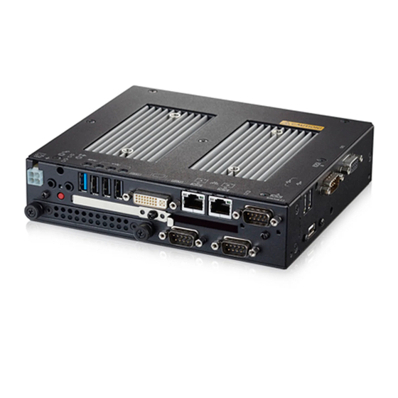
- Page 1 IPC Series BOX-PC BX-S959SD Series Fanless, Atom E3845, CFast, HDD/SSD, DC input User’s Manual CONTEC CO., LTD.
-
Page 2: Check Your Package
None None None The user's manual for this product is available as a PDF file through CONTEC’s Web site. The user's manual provides such information as hardware settings, functions for each component, and BIOS settings. Refer to it as necessary. -
Page 3: Product Configuration Image
No part of this document may be copied or reproduced in any form by any means without prior written consent of CONTEC CO., LTD. CONTEC CO., LTD. makes no commitment to update or keep current the information contained in this document. -
Page 4: Table Of Contents
Limited One-Year Warranty ......................10 How to Obtain Service........................10 Liability ............................. 11 Safety precaution ..........................11 ◆Safety infomation........................11 ◆Caution on the BX-S959SD Series ..................11 2.SYSTEM REFERENCE Specification ............................14 Power Management Features ......................16 Power Requirements .......................... 16 ◆Power Consumption ........................ - Page 5 ◆DC Power Input Connector: DC-IN ..................55 ◆POWER SW ........................... 56 ◆LINE OUT Interface: LINE OUT ................... 56 ◆MIC IN Interface: MIC ......................56 ◆DVI-I interface: DVI-I ......................57 ◆USB3.0 Port: USB3.0 ......................59 ◆USB2.0 Port: USB2.0 ......................59 BX-S959SD Series User’s Manual...
- Page 6 ◆Serial Port Interface: SERIAL A, B, C, D ................62 ◆DIO Port: DIO ........................64 6.APPENDIX POST Codes ............................66 SERIAL I/O Address and Register Function ..................69 Watch-Dog-Timer ..........................75 Battery ............................... 78 7.LIST OF OPTIONAL PRODUCT BX-S959SD Series User’s Manual...
- Page 7 BX-S959SD Series User’s Manual...
-
Page 8: Introduction
Embedded-type CPU have been adopted. The use of readily available parts ensures the ease of the use of the product. In addition, the use of Contec-customized BIOS allows support to be provided at the BIOS level. This product is available in the following 6 models: - Base model with Intel Atom Processor E3845 1.91GHz... -
Page 9: Features
- Safety design required for embedded applications For Windows Embedded Standard installed model, it is possible to use the EWF*2 function of OS. It is designed for safety required for embedding purpose, for example, prohibiting unwanted writing to the CFast BX-S959SD Series User’s Manual... -
Page 10: Supported Os
The separately available AC adapter adds support for 100 - 240VAC power. ◆Supported OS - Windows 7 32-bit. - Windows 7 64-bit. - Windows 8.1 32-bit. - Windows 8.1 64-bit. - Windows 10 32-bit. - Windows 10 64-bit. BX-S959SD Series User’s Manual... -
Page 11: Customer Support
You can download updated driver software and differential files as well as sample programs available in several languages. ■Note! For product information Contact your retailer if you have any technical question about a CONTEC product or need its price, delivery time, or estimate information. Limited One-Year Warranty CONTEC products are warranted by CONTEC CO., LTD. -
Page 12: Liability
CAUTION indicates a potentially hazardous situation which, if not avoided, may result in minor or moderate injury or in property damage. ◆Caution on the BX-S959SD Series Handling Precautions WARNING Always check that the power supply is turned off before connecting or disconnecting power cables. - Page 13 To prevent corruption of files, always shutdown the OS before turning off this product. CONTEC reserves the right to refuse to service a product modified by the user. In the event of failure or abnormality (foul smells or excessive heat generation), unplug the power cord immediately and contact your retailer.
- Page 14 Operation of this equipment in a residential area is likely to cause harmful interference at his own expense. WARNING TO USER Change or modifications not expressly approved the manufacturer can void the user's authority to operate this equipment. BX-S959SD Series User’s Manual...
-
Page 15: 2.System Reference
Power Management Supports PC98/PC99 ACPI Power management *1: When using HDD / SSD Storage device, only CFast x 1 storage can be selected. If using CFast x 2 storage drvice, cannot use HDD / SSD Storage device. BX-S959SD Series User’s Manual... - Page 16 When installing storage device: About 2.0kg *2: If you use the 1000BASE-T, be careful of the operating temperature. For more details on this, refer to chapter3, Installation Requirements. *3: Use a power cable shorter than 3m. BX-S959SD Series User’s Manual...
-
Page 17: Power Management Features
Rise time for power supply: 2 ms - 30 ms The following table lists the power supply’s tolerances for DC voltages: Table 2.3. DC voltage tolerance DC Voltage Acceptable Tolerance + 12V - 24V + 10.8V - 31.2V BX-S959SD Series User’s Manual... -
Page 18: Physical Dimensions
BX-S959SD-DC7xxx BX-S959SDF2-DC7xxx * The length (L) from the tip of M4 boss to the M4 screw tip should be 5mm or less. If not doing so, it may be exactly fixed. Figure 2.1. BX-S959SD-DC7xxx / BX-S959SDF2-DC7xxx BX-S959SD Series User’s Manual... -
Page 19: 3.Hardware Setup
Be sure to connect the keyboard and mouse to it before turning the power on for the first time. Be sure to connect the display before turning the power on. Connecting the display after turning the power on may prevent it from being displayed properly. BX-S959SD Series User’s Manual... -
Page 20: Hardware Setup
- Be careful not to mistake the orientation of the CFast card when inserting it. Also, do not use excessive force when inserting the CFast card. Doing so may damage the connector. - Do not drop or otherwise subject the CFast card to strong impacts before insertion. Doing so may damage the card. BX-S959SD Series User’s Manual... -
Page 21: Attaching The Hdd And Ssd
Do not tighten screws with excess force. Figure 3.3. Attaching the Attachment Fittings Screw holes may be damaged if screws are tightened with a torque greater than the specified torque. The specified tightening torque is 5 - 6kgf・cm. BX-S959SD Series User’s Manual... -
Page 22: Attaching The Fg
The FG pin of this product is connected to the GND signal of the DC power connector (DC-IN). Note that the connection cannot be cut off. Screw holes may be damaged if screws are tightened with a torque greater than the specified torque. The specified tightening torque is 5 - 6kgf・cm. BX-S959SD Series User’s Manual... -
Page 23: Fastening The Cable
Figure 3.5. Attaching the cable clamp (2) The photo below shows an example of using a cable clamp. Fix the cable with a clamp without applying stress to the connector. Figure 3.6. Using example of cable clamp BX-S959SD Series User’s Manual... -
Page 24: Installation Requirements
Figure 3.7. Installation Orientation Note that even though the ambient temperature is within the specified range, an operational malfunction may occur if there is other device generating high heat; the radiation will influence the product to increase its temperature. BX-S959SD Series User’s Manual... - Page 25 Do not install this product in completely sealed spaces, except when it is possible to adjust the internal temperature using an air conditioner or similar equipment. Temperature increase caused by long-term usage may result in operational malfunction or other problems. BX-S959SD Series User’s Manual...
- Page 26 When making use of the product, the air current should be adjusted to prevent that all the temperatures measured at the measurement points exceed the specified temperature. - Ground conditions 1 Body - Ground conditions 2 to 5 Save & - Ground conditions 6 Body Figure 3.9. Operating temperature BX-S959SD Series User’s Manual...
-
Page 27: 4.Bios Setup
If the message disappears before you respond and you still wish to enter Setup, restart the system to try again by turning it OFF then ON on the system case. You may also restart by simultaneously pressing <Ctrl>, <Alt>, and <Delete> keys. BX-S959SD Series User’s Manual... -
Page 28: Using Setup
AMI and system manufacturers to ensure maximum performance and reliability. Even changing the chipset settings slightly can result in an unavoidable need for repairs. ◆A Final Note About Setup The information in this chapter is subject to change without notice. BX-S959SD Series User’s Manual... -
Page 29: Main Menu
Security Set the password to be used to protect the security of the system. Boot Configure the settings related to how the system will boot. Save & Exit Load/save setup items and exit the setup menu. BX-S959SD Series User’s Manual... -
Page 30: Main
Administrator Displays the access rights level. *1 When the model is BX-S959SD series, the project version is “B959C000”. in contrast, when the model is BX-S959SDF2 series, the project version is “B959F000”. This table shows the selections that you can make on the Main Menu. -
Page 31: Advanced
View such information as the CPU temperature. CPU Configuration Configure the CPU settings. PPM Configuration Configure the power saving function settings. SATA Configuration Configure the SATA controller settings. CSM Configuration Configure such settings as the boot options. BX-S959SD Series User’s Manual... -
Page 32: Acpi Settings
Sets the time the system will automatically turn on. RTC Wake up Minute 0-59 Sets the minute the system will automatically turn on. RTC Wake up Second 0-59 Sets the second the system will automatically turn on. BX-S959SD Series User’s Manual... -
Page 33: Super Io Configuration
Serial Port B Refer to Table 4.8. Configuration T.P. Serial Refer to Table 4.9. Configuration RS-485 Port Refer to Table 4.10. Configuration Ext-Serial Port A Refer to Table 4.11 Configuration Ext-Serial Port B Refer to Table 4.12 Configuration BX-S959SD Series User’s Manual... - Page 34 Input Input : GPIO 2 Output High Use as a general-purpose input. GPIO 3 Output High : Output Low GPIO 4 Use as a general-purpose output. GPIO 5 Output Low : Use as a general-purpose output. BX-S959SD Series User’s Manual...
-
Page 35: H/W Monitor
Enter: Select +/-: Change Opt. F1: General Help F2: Previous Values F3: Optimized Defaults F4: Save & Exit ESC: Exit Version x.xx.xxxx. Copyright (C) 20xx American Megatrends, Inc. Figure 4.5. H/W Monitor (Actual Display May Vary.) BX-S959SD Series User’s Manual... -
Page 36: Cpu Configuration
Version x.xx.xxxx. Copyright (C) 20xx American Megatrends, Inc. Figure 4.6. CPU Configuration Table 4.13. CPU Configuration Item Option Description Disabled Execute Disable Bit Do not change this setting. Enabled Disabled Intel Virtualization Do not change this setting. Technology Enabled BX-S959SD Series User’s Manual... -
Page 37: Ppm Configuration
Figure 4.7. PPM Configuration Table 4.14. PPM Configuration Item Option Description Disabled EIST Do not change this setting. Enabled Disabled CPU C-State Report Do not change this setting. Enabled Disabled SOix Do not change this setting. Enabled BX-S959SD Series User’s Manual... -
Page 38: Sata Configuration
Changing this setting will require the OS AHCI Mode to be reinstalled. Enabled Configure the operation settings for SATA Serial-ATA Port 0 port0. Disabled Enabled Configure the operation settings for SATA Serial-ATA Port 1 port1. Disabled BX-S959SD Series User’s Manual... -
Page 39: Csm Configuration
UEFI and Legacy Boot option filter Do not change this setting. Legacy only UEFI only Do not launch Storage Do not change this setting. UEFI Legacy Do not launch Video Do not change this setting. UEFI Legacy BX-S959SD Series User’s Manual... -
Page 40: Chipset
ESC: Exit Version x.xx.xxxx. Copyright (C) 20xx American Megatrends, Inc. Figure 4.10. Chipset The following items are available. North Bridge Configure the operation settings for North Bridge. South Bridge Configure the operation settings for South Bridge. BX-S959SD Series User’s Manual... -
Page 41: North Bridge
Refer to Table 4.15. LCD Control Refer to Table 4.16. 2 GB 2.25 GB Max TOLUD Do not change this setting. 2.5 GB 2.75 GB 3 GB Enabled Bypass SPD Detect Do not change this setting. Disabled BX-S959SD Series User’s Manual... -
Page 42: Intel Igd Configuration
Do not change this setting. Disabled Disabled PAVC Do not change this setting. LITE Mode SERPENT Mode 128M 160M 192M 224M 256M DVMT Pre-Allocated Do not change this setting. 288M 320M 352M 416M 448M 480M 512M BX-S959SD Series User’s Manual... - Page 43 Table 4.18. Intel GOP Configuration <2/2> Item Option Description 128MB DVMT Total Gfx Mem 256MB Do not change this setting. 128MB Aperture Size 256MB Do not change this setting. 512MB GTT Size Do not change this setting BX-S959SD Series User’s Manual...
-
Page 44: Lcd Control
Disabled Configure the settings for the port that will be Secondary IGFX Boot output as the auxiliary display at start-up. Display This will make it possible to use an auxiliary display after the OS boots. BX-S959SD Series User’s Manual... -
Page 45: South Bridge Configuration
Last State Last State: If the power is turned off while the system is on, the system will start the next time the power supply starts. Quiet Serial IRQ Mode Do not change this setting. Continuous BX-S959SD Series User’s Manual... -
Page 46: Azalia Hd Audio Configuration
Save & Exit ESC: Exit Version x.xx.xxxx. Copyright (C) 20xx American Megatrends, Inc. Figure 4.15. Azalia HD Audio Configuration Table 4.21. Azalia HD Audio Configuration Item Option Description Disabled Audio Controller Configure the Audio Controller settings. Enabled BX-S959SD Series User’s Manual... -
Page 47: Usb Configuration
This should normally be set to Smart Auto. USB3.0 (XHCI) Support Disabled Set to Smart Auto to set up a USB 3.0 driver Smart Auto in Windows 7. Enabled USB2 Link Power Management Do not change this setting. Disabled BX-S959SD Series User’s Manual... - Page 48 Table 4.22. USB Configuration <2/2> Item Option Description Do not change this setting. Enabled Setting to Disabled will prevent all USB USB2.0 (EHCI) Support Disabled ports from operating. BX-S959SD Series User’s Manual...
-
Page 49: Lan Configuration
Item Option Description Enabled Onboard LAN A Controller Can not change this setting. Disabled Enabled Onboard LAN B Controller Configure the LAN B Controller settings. Disabled Do not launch Configure the PXE boot settings. UEFI Legacy BX-S959SD Series User’s Manual... -
Page 50: Security
Enter a password at least 3 characters long twice. To disable the password, enter the Administrator Password entry screen again. Be careful to not forget the password. If you forget the password, the product will have to be repaired at an extra cost. BX-S959SD Series User’s Manual... -
Page 51: Boot Configuration
Set the start order of the connected Priorities HDD/CFast/USB removable drives. (Specify any device) XXXXXXXX Floppy Drive BBS Set the start order of the connected Priorities USB floppy drives. (Specify any device) *1 : Appears when the device is connected. BX-S959SD Series User’s Manual... -
Page 52: Save & Exit
Discard Change and Exit Exit without saving the changed settings. Save Changes and Reset Save the changed settings and restart. Discard Change and Reset Restart without saving the changed settings. Save Changes Save the changed settings. Discard Changes BX-S959SD Series User’s Manual... - Page 53 Return the settings to the user default values. Boot Override Configure the settings for temporary booting from a connected device other than that set in Boot Configuration. The bootable devices will be displayed in place of XXXX. BX-S959SD Series User’s Manual...
-
Page 54: 5.Each Component Function
5 . Each component function Component name ◆Front view BX-S959SD Series Figure 5.1. Component Name < 1 / 2 > ◆Rear view BX-S959SD Series Figure 5.2. Component Name < 2 / 2 > BX-S959SD Series User’s Manual... -
Page 55: System Configuration
SERIAL C RS232C connector (9pin D-SUB, male) SERIAL D RS232C / 422 /485 connector (9pin D-SUB, male) General-purpose I/O connector (9 pin D-SUB, female) HDD/SSD 2.5” SATA HDD slot System Configuration BX-S959SD Series Figure 5.3. System Configuration BX-S959SD Series User’s Manual... -
Page 56: Component Function
ON (Red) You can control the behavior of LED from the user application. API that controls STATUS LED is available. For more information, visit the CONTEC's Web site. ◆DC Power Input Connector: DC-IN To supply the power, always use the power supply listed below. -
Page 57: Power Sw
The product is equipped with a connector for line output. As such, headphones or an amplified speaker can be connected. ◆MIC IN Interface: MIC The product is equipped with a connector for microphone input. As such, a microphone can be connected for voice input. BX-S959SD Series User’s Manual... -
Page 58: Dvi-I Interface: Dvi-I
◆DVI-I interface: DVI-I A DVI-I interface is provided. A CRT display (or a 15-pin D-SUB CRT when the included DVI–Analog RGB conversion adapter is used) or a flat-panel display from CONTEC can be connected. The connector name is DVI (DVI-I 29 pin). - Page 59 This will not affect how the digital display appears. However, change the multi-display settings as necessary. To change the settings from digital output to analog output, change the settings from the standard Windows properties screen. BX-S959SD Series User’s Manual...
-
Page 60: Usb3.0 Port: Usb3.0
DATA- DATA+ USB_GND SSRX- SSRX+ USB_GND SSTX- SSTX+ ◆USB2.0 Port: USB2.0 This product is equipped with 6 channel for USB 2.0 TYPE-A interface. Table 5.7. USB2.0 Connector Signal name Pin No. USB2.0 USB_VCC DATA- DATA+ USB_GND BX-S959SD Series User’s Manual... -
Page 61: Giga Bit-Ethernet: Lan A, B
Attention should to be paid to the guaranteed operating range of temperature in using 1000BASE-T. For more details on this, refer to chapter3, Installation Requirements. Note that the Ethernet should be configured as 100BASE-TX or 10BASE-T in using under the temperature 0 - 50°C. BX-S959SD Series User’s Manual... -
Page 62: Cfast Card Connector: Cfast1, 2
The CFast card is not hotpluggable. While this product is turned on, do not insert or remove the CFast card or touch the CFast card connector on the product. Doing so may lead to a malfunction or failure. BX-S959SD Series User’s Manual... -
Page 63: Serial Port Interface: Serial A, B, C, D
Pin No. Signal name Meaning Direction Carrier detect Input Received data Input Transmitted data Output Data terminal ready Output Signal ground ----- Data set ready Input Request to send Output Clear to send Input Ring indicator Input BX-S959SD Series User’s Manual... - Page 64 Table 5.12. RS-232C/422/485 SERIAL Port Connector 9-pin D-SUB (MALE) Connector type Pin No. RS-232C RS-422 RS-485 TX-/RX- TX+/RX+ RTS- RTS+ CTS+ CTS- BX-S959SD Series User’s Manual...
-
Page 65: Dio Port: Dio
5VDC 5mA Input section Non-isolated 5VTTL level (positive logic; with internal 3.3 V, 1 kΩ pull- Input format Output section Non-isolated open drain (positive logic; with internal 3.3 V, 1 kΩ pull- Output format BX-S959SD Series User’s Manual... - Page 66 Example 1 : To set GPIO4 to input mode and all the other GPIO ports to output mode, specify "0001 0000" ("10h"). Example 2 : To set GPIO2 and GPIO5 to input mode and all the other GPIO ports to output mode, specify "0010 0100" ("24h"). BX-S959SD Series User’s Manual...
-
Page 67: 6.Appendix
Post memory, South Bridge initialization starts 3Ch - 3Eh Post memory, South Bridge initialization (Specific South Bridge module) 3Fh - 4Eh OEM post memory initialization code DXE IPL startup < Driver Execution Environment (DXE) phase > DXE core startup NVRAM initialization BX-S959SD Series User’s Manual... - Page 68 ASL for reserved (Refer to ACPI/ASL Checkpoints) Setup input wait ASL for reserved (Refer to ACPI/ASL Checkpoints) Boot preparation events Legacy boot event Boot Service event ends Virtual address maps run-time settings begin. Virtual address maps of runtime configuration exit BX-S959SD Series User’s Manual...
- Page 69 From S2 sleep state during system restoration From S3 sleep state during system restoration From S4 sleep state during system restoration Move to system ACPI mode. The interrupt controller PIC mode. Move to system ACPI mode. The interrupt controller APIC mode. BX-S959SD Series User’s Manual...
-
Page 70: Serial I/O Address And Register Function
Interrupt ID register 03FBH Line control register 03FCH Modem control register 03FDH Line status register 03FEH Modem status register 03FFH Scratch register DLAB (Divisor Latch Access Bit) : The value in bit 7 of the line control register. BX-S959SD Series User’s Manual... - Page 71 RBR: Reciever Buffer Register [DLAB=O] Register dedicated to read received data from 03F8H DLL: Divisor Latch (LSB) [DLAB=1] Baud rate setting register (LSB) 03F9H DLH: Divisor Latch (MSB) [DLAB=1] Baud rate setting register (MSB) 03F9H IER: Interrupt Enable Register [DLAB=0] BX-S959SD Series User’s Manual...
- Page 72 Table 6.3. Function of Each Register < / 4 > I/O address Description 03FAH IIR : Interrupt Identification Register 03FBH LCR : Line Contror Regester BX-S959SD Series User’s Manual...
- Page 73 Table 6.3. Function of Each Register < 3 / 4 > I/O address Description 03FCH MCR: Modem Control Register 03FDH LSR: Line Status Regester BX-S959SD Series User’s Manual...
- Page 74 Table 6.3. Function of Each Register < 4 / 4 > I/O address Description 03FEH MSR : Modem Status Register 03FFH SCR : Scratchpad Register This is an 8-bit, readable/writable register which is available to the user to allow data to be saved temporarily. BX-S959SD Series User’s Manual...
- Page 75 3600 4800 7200 9600 14400 19200 28800 38400 57600 76800 115200 153600 230400 Example : To set 9,600 bps, write "00" to the (MSB) divisor latch register and "12 (decimal)" to the (LSB) divisor latch register. BX-S959SD Series User’s Manual...
-
Page 76: Watch-Dog-Timer
It is also possible not to perform [WDT Stop] instead of performing [WDT Stop] to [WDT Start], but to perform [WDT Start] continuously at the time of a re-start. (2) Example programming The following example is written in Intel8086 assembly language. =============== <WDT Initial> =============== .MODEL SMALL BX-S959SD Series User’s Manual... - Page 77 ;--- Set WDT Timer --- ch,0F1h cl,WDTT call Set_IO ;--- Close NCT610xD IO --- dx,IO_Port al,0AAh dx,al ;--- End Program --- ah,4ch ; ---------------------------------------- ch = Index cl = Data ; ---------------------------------------- Get_IO Proc Near dx,IO_Port al,ch dx,al dx,IO_Port+1 BX-S959SD Series User’s Manual...
- Page 78 Get_IO Endp Set_IO Proc Near dx,IO_Port al,ch dx,al dx,IO_Port+1 al,cl dx,al Set_IO Endp END BEGIN The timer’s intervals have a tolerance of ± 2 seconds BX-S959SD Series User’s Manual...
-
Page 79: Battery
: 1g or less Removing the battery Remove the battery according to the following figure. Removing the battery Remove the battery according to the following figure. Disposing the battery Dispose the removed battery properly as instructed by local government. BX-S959SD Series User’s Manual... -
Page 80: 7.List Of Optional Product
If a product other than our option is used, need to used below 40℃surroundings, or the normal operation may be impaired or the functions may be limited. *Visit Contec website regading information on the optional products. BX-S959SD Series User’s Manual... - Page 81 Japanese http://www.contec.co.jp/ English http://www.contec.com/ Chinese http://www.contec.com.cn/ All rights reserved. This product and this document are protected by copyright law. Unauthorized copying, duplication, reproduction, and tampering are prohibited. [11282017] [02092017] Management No NA05318 [11282017_rev2] Parts No LYUK911 BX-S959SD Series User’s Manual...
Need help?
Do you have a question about the BX-S959SD Series and is the answer not in the manual?
Questions and answers