Table of Contents
Advertisement
Quick Links
Download this manual
See also:
User Manual
Advertisement
Table of Contents

Subscribe to Our Youtube Channel
Related Manuals for Lumens CL510


Summary of Contents for Lumens CL510
-
Page 1: Document Camera
CL510 Document Camera Installation Guide Version: V06 Date: 2015/05/07... -
Page 2: Table Of Contents
Table of Contents Copyright Information ............................2 Chapter 1 Safety Instructions ..........................3 Precautions ..............................3 FCC Warning ..............................3 FDA Warning ..............................3 EN55022 (CE Radiation) Warning ........................3 EN60825 (Laser) Warning ..........................3 ... -
Page 3: Copyright Information
Lumens is a trademark that is currently being registered by Lumens Digital Optics Inc. Copying, reproducing or transmitting this file is not allowed if a license is not provided by Lumens Digital Optics Inc. unless copying this file is for the purpose of backup after purchasing this product. -
Page 4: Chapter 1 Safety Instructions
Chapter 1 Safety Instructions Always follow these safety instructions when setting up and using the Ceiling Camera: 1. Use attachments only as recommended. 2. Use the type of power source indicated on the Ceiling Camera. If you are not sure of the type of power available, consult your distributor or local electricity company for advice. -
Page 5: Chapter 2 Package Contents
Chapter 2 Package Contents Instruction for CL510 Quick Start Guide Remote Control Installation (For download of other language versions, please visit Lumens website) Power Adapter USB Cable VGA Cable IR extender Appearance may vary depending on country/region Ceiling Mount /... -
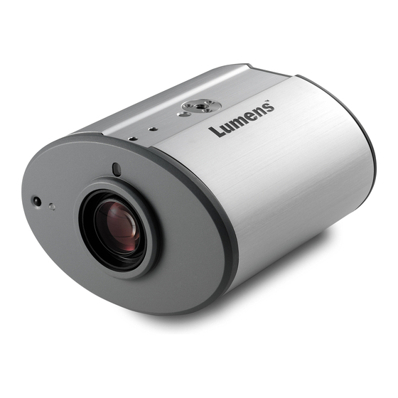
Page 6: Chapter 3 Product Description
Chapter 3 Product Description Body size 3.1.1 The size of CL510 is as follows: Length: 126mm (4.96inch) Width: 86mm (3.39inch) Height: 140.9mm (5.55inch) English - 5... - Page 7 3.1.2 The size of CL510 together with U-hanger is as follows: Length: 126mm (4.96inch) Width: 86mm (3.39inch ) Height: 220mm (8.66inch) English - 6...
-
Page 8: Io Description
IO description 1. DC IN: Power input 2. ETHERNET: RJ-45 Network cable interface 3. DVI OUT: DVI Image out 4. RS232: RS232 Interface 5. VGA OUT: VGA Image out 6. IR: IR Interface 7. DIP SWITCH: DIP Switch setting 8. USB PORT (A-type): USB Port 9. -
Page 9: Chapter 4 Installation And Connections
Chapter 4 Installation and Connections Installation and connection of CL510 Ceiling Camera requires special skills. To install by yourself, please follow necessary steps, ensure steady and tight installation of the device, and pay attention to your safety to avoid any accident. - Page 10 To achieve the best effect, please ensure that the machine is set at a distance of not more than 2 meters away from the object to be captured. 2 meters or less 4.1.5 Schematic diagram for the size of U-hanger and preparation before installation 4.1.5.1 Schematic diagram for the size of U-hanger The installation personnel should prepare the screw hanger in compliance with the size of the hole used for securing the U-hanger.
-
Page 11: Switch Setting
Please follow the instruction for the screw hanger to install it on the ceiling. Screw the device onto the screw hanger and complete the installation. 4.2 Switch setting <Note> You should unplug and reconnect the power cord, and then restart the CL510 for all DIP switch settings to take effect. Output Mode... -
Page 12: System Diagram
4.3 System diagram Computer Router or IR extender Computer Projector or monitor Set up the power frequency Set the applicable power frequency depending on different regions. Please refer to Appendix 1 for applicable frequency. 4.4.1 After using the remote control to turn on the power, press [MENU] on the remote control to enter the Service Menu. -
Page 13: Af Table Set For Auto Focus Setting
Adjust right and left Adjust up and down 4.5.5 Adjust the cross laser mark (red box) deviated on the screen to the center point of the blue positioning mark, as shown in the following figure: 4.6 AF Table Set for auto focus setting 4.6.1 Set up AF table This setting can speed up the AF operation. - Page 14 4.6.2 Set up the Default Zoom Press [FREEZE] -> [DEL] -> [ENTER] on the remote control to enter the Service Menu. Press [ ] or [ ] to select the [Image] menu. Press [ ] to <Without Close-up Lens> -> [ Default Zoom Setting]. <Note>...
-
Page 15: Chapter 5 Troubleshooting
Chapter 5 Troubleshooting This chapter describes problems you may encounter while using CL510. If you have questions, please refer to related chapters and follow all the suggested solutions. If the problem still occurred, please contact your distributor or the service center. -
Page 16: Attachment 1
Attachment 1 World voltage & frequency Region/Country Region/Country Region/Country Chinese English Chinese English Chinese English 阿 富 汗 Afghanistan 50 大 陸 China 50 關 島 Guam 阿 爾 及 利 亞 Algeria 50 哥 倫 比 亞 Colombia 60 石 榴... - Page 17 Region/Country Region/Country Region/Country Chinese English Chinese English Chinese English 智 利 Chile 50 格 陸 蘭 Greenland 50 賴 比 瑞 亞 Liberia 利 比 亞 Libya 50 阿 曼 Oman 50 敘 利 亞 Syria 盧 森 堡 Luxembourg 50 巴...
Need help?
Do you have a question about the CL510 and is the answer not in the manual?
Questions and answers