Advertisement
Quick Links
Rev. 141120
CONTENTS
SAFETY INFORMATION... ..................................................
PRODUCT OVERVIEW .......................................................
SPECIFICATION................................................................
INSTALLATION..................................................................
Before attempting to connect or operate this product, please read these
instructions carefully and save this manual for future use.
Ax52 Dome Camera Series
Instruction Manual
2
4
6
8
Advertisement

Related Manuals for i3 International Ax52 Series


Summary of Contents for i3 International Ax52 Series
- Page 1 Ax52 Dome Camera Series Instruction Manual Rev. 141120 CONTENTS SAFETY INFORMATION............. PRODUCT OVERVIEW ............SPECIFICATION..............INSTALLATION..............Before attempting to connect or operate this product, please read these instructions carefully and save this manual for future use.
-
Page 2: Safety Information
SAFETY INFORMATION When installing your Annexxus system, be sure to avoid: • excessive heat, such as direct sunlight or heating appliances • moisture, dust, and smoke • strong magnetic fields • close to sources of powerful electromagnetic radiation, such as radios or TV transmitters •... - Page 3 SAFETY INFORMATION The triangle symbol with lightning arrow indicates that ungrounded “Hazardous Voltage” exists within the unit. The voltage level may cause personal electric shock hazards. The triangle symbol with exclamation mark indicates that there are important operation and maintenance instructions in the Instruction Manual.
-
Page 4: Product Overview
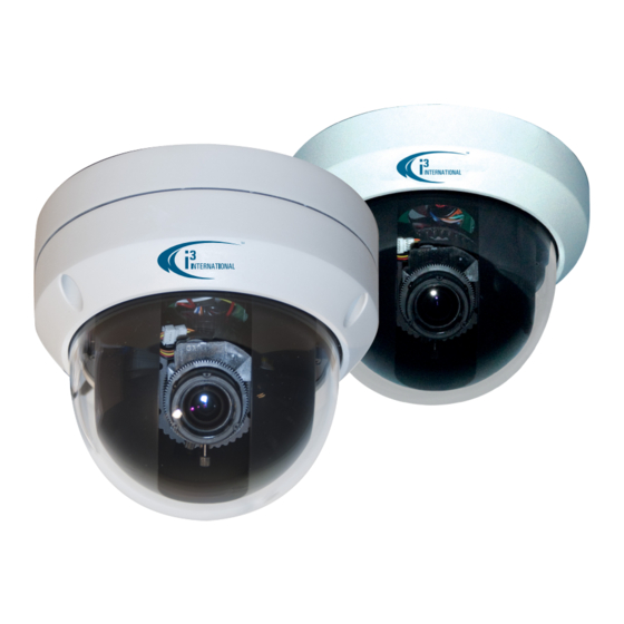
PRODUCT OVERVIEW 1. Key Features High Definition Images Clear and detailed HD quality images in all conditions. Unlike other megapixel cameras, AX52 offers higher resolutions and better frame rates. Blurry images are reduced and individuals and objects of interest come with perfect clarity. Triple Streaming The AX52 Network Camera is designed to show extreme image detail. - Page 5 PRODUCT OVERVIEW 2. Camera Overview 2.0 Camera Parts and Definitions • Power In (Red+/Black-): power connector, DC12V/AC24V • RJ-45 Ethernet Connector: network connection. Support PoE (Power over Ethernet) cable. • BNC: video output • Audio Out (Green): audio output • Audio In (Red): audio input •...
-
Page 6: Specification
SPECIFICATION Image system Image sensor 1/3" 2 MP image sensor optimized for low-light performance Effective pixels Effective 16:9 1920 (H) X 1080 (V) Image Compression Method Triple Streaming : H.264 / MPEG4 / Motion JPEG H.264 (16:9): 1920X1080(2M) 1280X720 (4:3): 1280x960(SXVGA) MPEG4 (16:9): 1920X1080(2M) 1280X720 (4:3): 1280x960(SXVGA) - Page 7 SPECIFICATION Other Mirror, Flip, System log, Time stamp, Snapshot, Event Management Primary Stream Bit Rate Control: CBR/VBR Local Storage Memory Card Support Micro SD/ Micro SDHC Card up to 32 GB SD card overwrite SD card store category Alarm /Ethernet Fail file format JPEG/ AVI Recording frame rate range between 1 to 3 fps Power Supply...
-
Page 8: Installation
INSTALLATION 3. Camera Installation Use the appropriate brackets and equipment to mount this camera. After installing the camera, your network camera should be accessed from your local network. 3.1 Package Content Item Description Network Dome Camera Printed Quick Start Guide CD-ROM ( User Manual, Annexxus Finder ) Guide Pattern Sticker... - Page 9 INSTALLATION 3.1.5 Camera Installation for ceiling mount and wall mount Drill the Mounting Location 1. Place the “Guide Pattern Sticker” on the desired location. 2. Drill 4 mounting holes and 1 cable entry hole. • Mark holes’ positions: secure the metal plate to the ceiling using the appropriate screws.
- Page 10 INSTALLATION Adjusting Camera Focus 1. Take off the screw (a.) Screw (a.) 2. Rotate the dome counter clockwise to unlock and pull free of the housing. Counter Clockwise 3. Remove the inner liner by gently pulling it free of the two notches in the housing.
- Page 11 INSTALLATION 4. Adjust the camera to your specification (Tilt). Pan (Angle about Tilt(Angle 90 degrees) 355 degrees) 5. Adjust the camera to your specification (Pan). Horizontal Rotation Note: When the tilt angle is less than 75 degrees there is no distortion...
- Page 12 INSTALLATION 6. Focusing loosen both screws (a.) and (b.) and turn the lens until ideal picture Screw (a.) Screw (b.) Varifocal Lens 7. Reattach the inner liner and dome when you are done adjusting the focus.
- Page 13 INSTALLATION 3.2 Network Connection Diagram 3.2 Hardware/Software Requirement Computer • i3 SRX-Pro Version 2.0 or higher • Windows Vista or XP as OS • Internet Explorer Version 6.0 or later • CPU: Intel Pentium Core 2 or higher • Memory: 1GB or more •...
- Page 14 INSTALLATION 3.4 Connecting the Camera to a Personal Computer This section details how to access the camera from a computer. 3.4.1 Setting IP This is a network-based camera and must be assigned an IP address first. • Enter a default IP address manually. The camera’s default IP address is 192.0.0.16 and subnet mask address is 255.255.255.0.
- Page 15 INSTALLATION 4. Start Internet Explorer and enter the set IP address (default is http://192.0.0.16). A login window will appear. Enter the default user name and to login. Default Login/Password: Firmware Version: AP_01-00-60-33_i02 Login: admin Password: 1234 Firmware Version: AP_01-00-60-35_i02, or higher Login: i3admin Password: i3admin...
- Page 16 INSTALLATION 3.5 Using “Annexxus Finder” to Search Camera’s IP Address “Annexxus Finder” is a program which helps users finds network cameras. Please note that “Annexxus Finder” is only compatible with Windows XP. 1. Insert the CD in the CD-ROM drive. 2.
- Page 17 INSTALLATION 4.1 Live View Live view is designed for general users to control the camera. “Snapshot”, “Live” and “Setup” functions are listed on the live view. Please note, only administrators can access "Setup" to configure camera settings. 4.2 Snapshot The “Snapshot” function is for snapshot capture. Press the “Snapshot” button to take a link to let user choose local storage to save (jpg/bmp) user prefer by right clicking on this link.
- Page 18 INSTALLATION 5. Setup Mode Click on “setup” to configure camera settings.
- Page 19 INSTALLATION 5.1 Basic Setting Every parameter of “Basic Setting” affects the displayed image. Specify appropriate parameters in the following section. Advance or Basic Button “Basic Image” is used to change any picture setting on the camera. Remember to click “Save” to keep your settings. •...
- Page 20 INSTALLATION 5.2 Advance Setting Video Page Frequency: “50 Hz” and “60 Hz” are provided for reducing flicker. TV System: "NTSC" and "PAL" are provided for different TV system settings. • Note: This setting base on model (NTSC/PAL) type. Mirror: • OFF: turn off this function. •...
- Page 21 INSTALLATION MJPEG SETTING • Resolution: Choose the resolution size. Choices include 1080P, SXVGA, 720P, XGA, SVGA, D1 • Quality: Set the image’s quality as High, Normal or Low. • Frame Rate: Frame rate is the image transfer speed. 30 fps is 30 image transmissions per second, 15 is 15 images transmission per second, 7.5 is 7.5 images transmission per second…etc.
- Page 22 INSTALLATION 5.2.1 Image Advanced Settings “White Balance”, “BLC”, “Brightness”, “Contrast”, “Saturation” and “Sharpness” are provided for you to set the quality of images. Please click the “Save” button to save your image settings. Advanced settings • White Balance Auto: select a white balance mode according to external lighting condition for the best color temperature.
- Page 23 INSTALLATION • BLC (Backlight Compensation): this function adjusts the image to compensate for areas that are too dark due to insufficient light. ◦ ON: enable the BLC function. ◦ OFF: disable the BLC function. • Brightness: adjust the image brightness level, Selectable values from 0% to 100%.
- Page 24 INSTALLATION 4. Default Gateway: leave 192.0.0.16 as default setting. It is not required if it is not used. Please contact your Network Administrator for Default Gateway information. 5. DNS: leave 192.0.0.16 as default setting. It is not required if it is not used. Please contact your Network Administrator for DNS information.
- Page 25 INSTALLATION In this section, you can configure the system settings, including “Time Stamp”, “Current Date & Time” and “New Date & Time”. Current Time It displays the current time on the camera. Date and time will be changed after you configure it in the “New Time”...
- Page 26 INSTALLATION 5.3.5 Update This function is designed to update firmware. Stop all camera operations when you update firmware. Do not turn off power or disconnect the internet connection during the firmware update process. Click “Restart Camera” after you have up- dated firmware successfully.
- Page 27 INSTALLATION 5.3.3 Users User List Displays the list of users. Only two roles can be specified, administrator (admin/i3admin) and guest (viewer). If you want to delete a user, select a user and then press the “Delete User” button Add/Modify User You can add a new user or modify a user’s information or authority.
- Page 28 INSTALLATION 5.3.6 Logs It displays all login and alarm records.
- Page 29 INSTALLATION 5.4.3 Alarm You can set to trigger alarms on the conditions that an event or action signal has been sent to the camera. • Trigger an Alarm When Ethernet is Lost: set an alarm condition when Ethernet disconnected. • Digital Input: send a signal to the camera to trigger an alarm. Check it to enable this function.
- Page 30 INTERNATIONAL INC. 1.866.840.0004 U.S.A. 440 Lawrence Bell Drive, Canada 780 Birchmount Road, www.i3international.com Suite 16, Williamsville Unit 16, Scarborough, NY, 14221 ON, M1K 5H4...
Need help?
Do you have a question about the Ax52 Series and is the answer not in the manual?
Questions and answers