Table of Contents
Advertisement
Quick Links
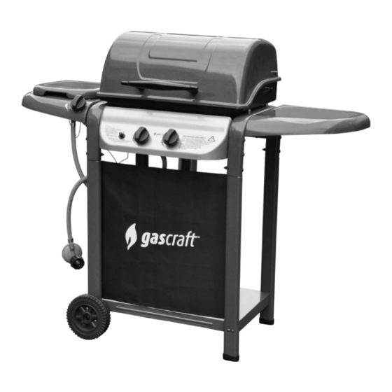
Assembly and Operating Instructions for
Photographs are not to scale.
Specifications subject to change
without prior notice.
•
For outdoor use only. Not for commercial use.
•
Read instructions before using the appliance. Failure to follow instructions could
result in death, serious bodily injury, and/or property loss.
Warning: accessible parts may be very hot. Keep young children and pets away.
•
Do not move the appliance during use.
•
Turn off the gas supply at the gas bottle after use.
•
Any modification of the appliance, misuse, or failure to follow the instructions may
•
be dangerous and will invalidate your warranty. This does not affect your statutory
WARNING
rights.
Retain these instructions for future reference.
•
Leak test annually, and whenever the gas bottle is removed or replaced. Check that
•
the hose connections are tight and leak test each time you reconnect the gas bottle.
For Flare-up control please refer to the 'OPERATION' section of this manual.
•
FOR YOUR SAFETY
If you smell gas:
1.
Shut off gas to the appliance.
2.
Extinguish any open flame.
3.
Open barbecue lid or hood.
4.
If odour continues, discontinue use and
contact your local dealer.
2 Burner Wagon Grill
Cruz
1.
2.
FOR YOUR SAFETY
Do not store or use petrol or other flammable
vapours or liquids in the vicinity of this or any
other appliance.
A gas bottle not connected for use must not be
stored in the vicinity of this or any other
appliance.
0359
Advertisement
Table of Contents

Related Manuals for gascraft cruz


Summary of Contents for gascraft cruz
- Page 1 Assembly and Operating Instructions for 2 Burner Wagon Grill Cruz Photographs are not to scale. Specifications subject to change without prior notice. 0359 • For outdoor use only. Not for commercial use. • Read instructions before using the appliance. Failure to follow instructions could result in death, serious bodily injury, and/or property loss.
-
Page 2: Parts List
Parts List Specifications subject to change without prior notice. For more details on hardware, please see the corresponding ‘Hardware Reference Diagram’. CODE PART Cruz Hood Hood Handle HOOD Hood Handle Spacer Hood Hinge Warming Rack Barbecue Body Main Burner Main Electrode Assembly... -
Page 3: Parts Diagram
Parts Diagram Specifications subject to change without prior notice. For more details on hardware, please see the corresponding ‘Hardware Reference Diagram’. - Page 4 Hardware Reference Diagram Specifications subject to change without prior notice. For more details on hardware, please see the corresponding ‘Hardware Reference Diagram’. CODE Illustration CODE Illustration...
- Page 5 Assembly IMPORTANT! TOOLS NEEDED FOR ASSEMBLY: Medium size flat blade or Phillips/Crosspoint screwdriver, • adjustable spanner or metric spanner set. The assembly of this barbecue requires 2 people. • Whilst every care is taken in the manufacture of this product, care must be taken during assembly in •...
- Page 6 Put the Left and Right Arch Supports (B7, B8) over the trolley assembly, secure with M6x60 Blots (D8) and M6 Nuts (D10). Note: The guide holes on top of body supports should be located in the rear side. Attach the Rear Support (B10) onto left / right arch supports using M6x75 Bolts (D9).
- Page 7 Insert the M6 Studs (D5) through Barbecue Body (B1) and secure with M6 Nuts (D10). Insert the M6x45 Bolts (D7) through barbecue body, Body Spacers (D11), left/right arch supports and secure with M6 Nuts (D10).
- Page 8 Place the Control Panel Heat Shield (B12) above the main valve and align the screw holes, then fix it onto control panel with two ST4.0x10 Screws (D1). Connect the control panel assembly to the left and right arch supports using the M6x60 Bolts (D8) and M6 Nuts (D10) as shown.
- Page 9 Remove the retaining nut from Ignition Pushbutton (B11), and then insert the pushbutton through control panel on left side, secure with the retaining nut as shown. Press the Knobs (B13) onto valve stems above the control panel. Feed the Grease Cup Holder (B14) through middle body hole as shown. Insert the venturi tube of the Main Burner (B2) through the big holes of barbecue body and secure with ST4.0x10 Screws (D1) at the bottom as shown.
- Page 10 Put the Main Electrode Assembly (B3) through barbecue body from upper side. Fix it onto the main burner with a ST4.0x10 Screw (D1) . Connect its wire onto the pushbutton, on the control panel. IMPORTANT - ENSURE THE ELECTRODE WIRE IS NOT IN CONTACT WITH THE BOWL. Insert the M6x15 Bolts (D6) through Hood Hinges (A4), Hood (A1) and secure with M6 Nuts (D10).
- Page 11 Insert the M6x75 Bolts (D9) through Handle Washers (D12), hood, Hood Handle Spacers (A3), and screw into Hood Handle (A2). Place the Flame Tamer (B4) over main burner with two studs through the hole in each side of the flame tamer. Make sure that it is level. Place the Cooking Grill (B5) into the body, ensure it is level.
- Page 12 M6x15 Bolt Attach the Right Side Shelf (C7) onto right arch support by inserting M6x15 Bolts (D6) through the right side shelf and screwing into right arch support. Insert the Side Burner Drip Tray (C6) into the two flat keyed holes in either side of the side burner shelf, repeat for remaining holes.
- Page 13 Feed the Side Burner Electrode (C5) into the guide hole in the side burner drip tray. Insert the Side Burner (C4) through the centre hole in side burner drip tray, feed the side burner stud through the guide hole in electrode bracket while laying the burner flat. Lock the side burner and side burner electrode with a M4 Wing Nut (D3), as shown in the diagram.
- Page 14 Place the Side Burner Grid (C3) onto the side burner shelf with four legs inserted into the holes in each corner of side burner shelf. M6x15 Bolt Attach the Side Burner Shelf (C1) Assembly onto the left arch support by inserting the M6x15 Bolts (D6) through the side burner shelf and screwing into the left arch support.
- Page 15 Insert the M4x10 Bolts (D2) through the side burner shelf, and screw into the side burner valve. Make sure that the venturi end fits over the gas outlet nozzle of the side burner valve. Press the Knob (B13) onto the side burner valve stem as shown. Connect the side burner electrode wire onto the Ignition Pushbutton (B11) as shown.
-
Page 16: Leak Testing
Place the Grease Cup (B15) into grease cup holder. ASSEMBLY IS NOW COMPLETE. PROCEED TO THE NEXT PAGE FOR INSTRUCTIONS ON OPERATION AND MAINTENANCE ALL JOINTS AND CONNECTIONS MUST NOW BE LEAK TESTED BEFORE USING THE BARBECUE. Leak test annually, and whenever the gas bottle is removed or replaced. LEAK TESTING Always perform a leak test in a well-ventilated area. -
Page 17: Gas, Regulator And Hose
to detect any gas leaking from joints and Important Information connections of the barbecue after assembly. n Leak test annually, and whenever the gas Please read these instructions carefully before assembly and use of your barbecue. bottle is removed or replaced. n Do not store flammable materials near this n Retain these... -
Page 18: Operation
combustible surface, including trees and fences lighting. Never light your barbecue with the and make sure that there are no heat sources hood or lid closed. near the barbecue (cigarettes, open flames, • Ensure all knobs are in the off position. Open spark etc.). - Page 19 Lighting the Side Burner cooked food warm or to warm items such as Push and turn the side burner control knob anti- bread rolls. It is advisable to place food clockwise to the high position. Push the ignitor (particularly fatty foods) to the front of the button rapidly until the side burner ignites.
-
Page 20: Care And Maintenance
IT SHOULD BE A POWDER TYPE. rust inhibitor and painted with barbecue paint or DO NOT REMOVE THE GREASE CUP. a heat resistant paint. • If the fire does not seem to be abating or • A chrome cleaner may be used on chrome parts appears to be worsening, contact your local if required. - Page 21 valve outlets. The gas bottle should always be stored outside, in a dry, well-ventilated area, away from any Flame Tamer sources of heat or ignition. Do not let children Remove any food residue from the flame tamer tamper with the bottle. surface with a plastic or wooden scraper or brass wire brush.
-
Page 22: Technical Specifications
Technical Specifications NOTES: Type of Gas: LPG Appliance Injector Heat Model No. Name Pressure Size Input Consumption Cruz WG-H2274 30mbar 0.89mm 446g/hr Side WG-H2274 30mbar 0.74mm 165g/hr Burner Test specification: 0359 BSEN498:1998 and BSEN484:1998 Supplied by:The Warehouse Ltd, Auckland, NZ... -
Page 23: Troubleshooting
Troubleshooting Problem Possible Cause Solution Burner will not light using the LP gas bottle is empty Replace with full bottle ignition system Faulty regulator Have regulator checked or replaced Obstructions in burner Clean burner Obstructions in gas jets or gas hose Clean jets and gas hose Reconnect wire Electrode or ignition button wire is...
Need help?
Do you have a question about the cruz and is the answer not in the manual?
Questions and answers