Table of Contents
Advertisement
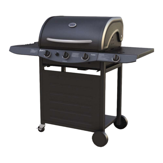
Toulon (Model#BG126N3B)
ASSEMBLY & OPERATING INSTRUCTIONS
FOR YOUR SAFETY
IF YOU SMELL GAS:
1. TURN OFF THE GAS SUPPLY AT BOTTLE
2. EXTINGUISH ALL NAKED FLAMES; DO NOT OPERATE ANY ELECTRICAL APPLIANCES.
3. VENTILATE THE AREA.
4. CHECK FOR LEAKS AS DETAILED IN THIS MANUAL.
5. IF ODOUR PERSISTS, CONTACT YOUR DEALER / GAS SUPPLIER IMMEDIATELY.
FOR OUTDOORS USE ONLY.
PLEASE READ INSTRUCTIONS CAREFULLY BEFORE ASSEMBLING.
RETAIN THIS MANUAL FOR FUTURE REFERENCE.
1
Advertisement
Table of Contents

Related Manuals for gascraft BG126N3B Toulon


Summary of Contents for gascraft BG126N3B Toulon
-
Page 1: For Your Safety
Toulon (Model#BG126N3B) ASSEMBLY & OPERATING INSTRUCTIONS FOR YOUR SAFETY IF YOU SMELL GAS: 1. TURN OFF THE GAS SUPPLY AT BOTTLE 2. EXTINGUISH ALL NAKED FLAMES; DO NOT OPERATE ANY ELECTRICAL APPLIANCES. 3. VENTILATE THE AREA. 4. CHECK FOR LEAKS AS DETAILED IN THIS MANUAL. 5. -
Page 2: Table Of Contents
TABLE OF CONTENTS Safety Information ………………………………………………………………………...3 Package Contents …………………………………………………………………………5 Illustrated Parts List ………………………………………………………………………..6 Hardware Contents ………………………………………………………………………..8 Preparation …………………………………………………………………………………..8 Assembly Instructions …………………………………………………………………….9 Leak Testing …………………………………………………………………………………16 Operation… ………………………………………………………………………………….16 Care and Maintenance ……………………………………………………………………20 Troubleshooting ……………………………………………………………………………..22... -
Page 3: Safety Information
IMPORTANT SAFETY INFORMATION Please read these instructions carefully before assembly and use. The Operator should have read and understood all the safety factors as explained in this manual before using this unit. He/She is also responsible for all third parties whilst the BBQ unit is in use. - Page 4 Clean and inspect the hose before each use. If there is evidence of abrasion, wear, cuts, or leaks, the hose must be replaced prior to operating the appliance. The replacement hose assembly will be that which is specified by the manufacturer. Keep the grill’s valve compartment, burners and circulating air passages clean.
-
Page 5: Package Contents
PACKAGE CONTENTS Part Description Quantity Part Description Quantity Left side frame Flame tamers Right side frame Cooking grill Base panel Warming rack Front cart panel Knob bezel Caster Knob Wheel assembly Side burner rack Right side table AA battery Left side table Cooking plate Grill housing assembly Drip pan... -
Page 6: Illustrated Parts List
ILLUSTRATED PARTS LIST... - Page 7 ILLUSTRATED PARTS LIST Cooking Plate...
-
Page 8: Hardware Contents
HARDWARE CONTENTS PREPARATION ____ Before beginning assembly of product, make sure all parts are present. Compare parts with package contents list and diagram above. If any part is missing or damaged, do not attempt to assemble the product. Contact customer service for replacement parts. Estimated Assembly Time: 30~40 minutes Tools Required for Assembly (not included);... -
Page 9: Assembly Instructions
ASSEMBLY INSTRUCTIONS Step 1: Attach left side frame (A) and right side frame (B) to the front cart panel (D) using four M6 X 12mm screws (BB). Step 2: Install the base panel (C) into the cart assembly using four lock washers (HH) and four M6 X 12mm screws (BB).Make sure the wing bolt preassembled on the base panel faces away from the front cart panel as shown. - Page 10 ASSEMBLY INSTRUCTIONS Step 3: Insert the caster wheel assemblies (E) into the left side frame (A) using wrench (FF) provided. Step 4: Install the wheel assemblies (F) on the right side frame (B) using two R-pins (DD) as shown. Step 5: 1) Place the left side table (H) and the right side table (G) at the top of the cart assembly using four lock washers (HH) and four M6 X 12mm screws (BB) as shown.
- Page 11 ASSEMBLY INSTRUCTIONS 3) Install the grill housing assembly using six washers (GG), lock washers (HH), and M6 X12mm screws (BB) as shown. First insert the back screws in an alternating pattern (install one screw on the left then install the next screw on the right side). NOTE: DO NOT TIGHTEN SCREWS UNTIL ALL FASTENERS ARE INSTALLED 4) Install the left side control panel with the grill housing assembly control panel using one M4 X 8mm screw (CC) as shown.
- Page 12 ASSEMBLY INSTRUCTIONS Step 6: 1) Install the electrode wire to ignition by plugging the end of the wire into the socket as shown. 2) Install the knob bezel (P) onto the right control panel (L) and side burner valve using two M4x8mm screws (CC), making sure to keep the side with the red line of the knob bezel upward as shown.
-
Page 13: Assembly Instructions
ASSEMBLY INSTRUCTIONS 4) Install the right side control panel on right side table using two M6x12mm screws (BB) as shown 5) Connect the side burner mixing tube with the C-clip (EE). -
Page 14: Assembly Instructions
ASSEMBLY INSTRUCTIONS Step 7: Install the knob (Q) on the right side table assembly as shown. Step 8: Open the lid and put two flame tamers (M) into the grill housing. Place cooking grill (N) and plate (T) in the grill housing. Ensure the grill is installed above the flame tamers. Install the warming rack (O) on the top of the grill housing. - Page 15 ASSEMBLY INSTRUCTIONS Step 9: Install the drip pan (J) under the grill housing at the back side. Install the grease collection pan (K) under the drip pan as shown. Step 10: To install battery, open the ignitor by turning counterclockwise until the ignitor button detaches itself.
-
Page 16: Leak Testing
(following previous steps noted here). If the gas leak persists, do not operate the appliance. Contact the Gascraft gas grill dealer for assistance. NEVER USE AN OPEN FLAME to test for leaks at anytime. If bubbles form over any of the joints there is a leak. - Page 17 heats the food on the grill. The natural juices produced during cooking fall onto the flame tamers below and vaporise. The subsequent rising smoke bastes the food, as it travels upwards, imparting that unique barbecued flavour. HOT PLATE COOKING The stainless steel burners heat the plate directly, which then cooks the food on contact. This allows for the cooking of smaller items, such as seafood, which could fall through the spaces grill.
-
Page 18: Operation Instructions
OPERATION INSTRUCTIONS Lighting Your Grill DANGER: Failure to open lid while igniting the grill or not waiting 5 minutes to allow the gas to clear if the grill does not light may result in an explosive flare-up which can cause serious bodily injury or death. Main Burners 1. - Page 19 OPERATION INSTRUCTIONS Lighting Burner With A Match: 1. Place a match in the end of the match holder that is pre-installed on the side of Grill Housing. Once lit, immediately place the flame through the hole as shown and position near the burner ports. 2.
-
Page 20: Care And Maintenance
CARE AND MAINTENANCE CAUTION: All cleaning and maintenance should be done when grill is cool and with the gas supply turned off at the LPG cylinder. DO NOT clean any grill part in a self-cleaning oven. The extreme heat will damage the finish. - Page 21 CARE AND MAINTANCE Cleaning the burner assembly – Make sure the grill is cool 1. Turn gas off at the control knobs and LPG cylinder. 2. Remove cooking grill & plate and flame tamers. 3. Remove grease collector. 4. Remove burner by unscrewing nut from beneath burner “foot” using a screwdriver and pliers.
-
Page 22: Troubleshooting
TROUBLESHOOTING... - Page 23 TROUBLESHOOTING Problem Possible Solutions The LPG regulator assembly supplied with this BBQ incorporates an excess flow device designed to supply the grill with sufficient gas flow under normal conditions, yet control excess gas flow. Rapid changes in pressure can trigger the excess flow device, providing a low flame and low temperature.
- Page 24 3. Make sure the gas supply is sufficient. 4. See if the LP tank is empty. Marketed by Gascraft Products P O Box 33 – 470 Takapuna, Auckland PLEASE KEEP YOUR RECEIPT AS PROOF OF PURCHASE.
Need help?
Do you have a question about the BG126N3B Toulon and is the answer not in the manual?
Questions and answers